
Structural
6.0 Structural
6.1 Radiographic Testing (RT)
The RT method is one of the NDT inspection methods used for inspecting the materials in the structural project by using either x-rays or gamma rays. Once the RT inspection request added in the NDT Inspection Request tab, you can add the RT inspection result details by using this Radiographic Testing (RT) tab.
- Click the Radiographic Testing (RT) tab in the Structural menu.
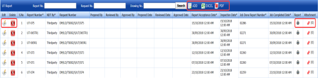
The RT Report page opens.
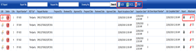
Figure 6.1: RT Report page
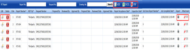
6.1.1 Add an RT Report
If you want to add an RT report, do the following,
- Click
 (ADD button) in the RT Report page. See Fig 6.1.
A new window opens to add an RT report.
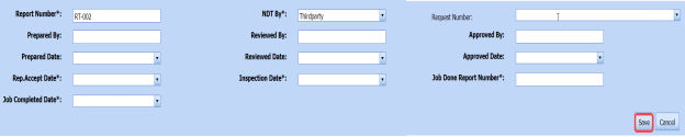
 Note: The fields notified with a symbol (*) are mandatory. You must enter the relevant details in that fields before saving.
 Tip: A report number for a new RT report will be updated automatically in the Report Number box.
 - In the NDT By box, select the creation of NDT whether by third party or internal from a drop-down list.
-
In the Request Number box, select an RT request number from a drop-down list.
-
In the Prepared By box, enter the name of a person who has prepared the RT report.
-
In the Prepared Date box, select the prepared date of the RT report.
-
In the Reviewed By box, enter the name of a person who has reviewed the RT report.
-
In the Reviewed Date box, select the reviewed date of the RT report.
-
In the Approved By boxes, enter the name of a person who has approved the RT report.
-
In the Approved Date box, select the approved date of the RT report.
-
In the Rep. Accept Date box, select the report accept date.
-
In the Inspection Date box, select the date of inspection.
-
In the Job Done Report Number box, enter the report number of completed inspection job.
-
In the Job Completed Date box, select the completed date of the inspection job.
-
Click Save.


The RT report is successfully added. Once you have added the RT report, you must add RT results for the respective added RT report.
6.1.2 Add RT Results
If you want to add the RT results for the respective RT report, do the following,
- Click the respective added RT report in the RT Report page. See Fig 6.1.
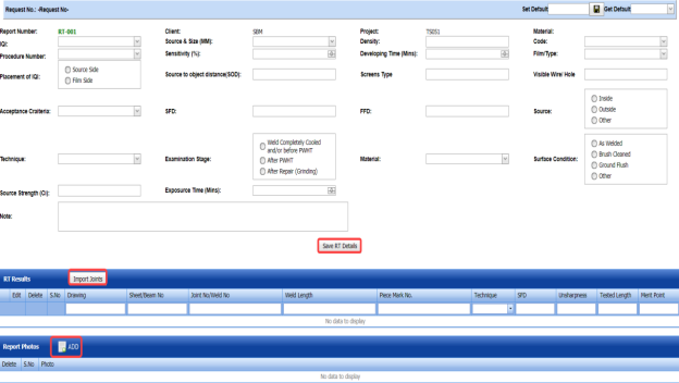
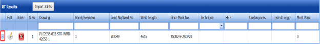
The RT Results window opens.

Figure 6.1.1: RT Results page
- In the Image Quality Indicator (IQI) box, select IQI from a drop-down list.
-
In the Source & Size (MM) box, select the RT source and their size from a drop-down list.
-
In the Density box, enter the radiographic density range.
-
In the Code box, select the code of the material from a drop-down list.
-
In the Procedure Number box, select the procedure number from a drop-down list.
-
In the Sensitivity (%) box, set the radiographic sensitivity by using up and down arrows.
-
In the Approved By boxes, enter the name of a person who has approved the RT report.
-
In the Approved Date box, select the approved date of the RT report.
-
In the Rep. Accept Date box, select the report accept date.
-
In the Inspection Date box, select the date of inspection.
-
In the Job Done Report Number box, enter the report number of completed inspection job.
-
In the Job Completed Date box, select the completed date of the inspection job.
-
Click Save.
The RT report is successfully added. Once you have added the RT report, you must add RT results for the respective added RT report.
6.1.2 Add RT Results
If you want to add the RT results for the respective RT report, do the following,
- Click the respective added RT report in the RT Report page. See Fig 6.1.
The RT Results window opens.

Figure 6.1.1: RT Results page
-
In the Image Quality Indicator (IQI) box, select IQI from a drop-down list.
-
In the Source & Size (MM) box, select the RT source and their size from a drop-down list.
-
In the Density box, enter the radiographic density range.
-
In the Code box, select the code of the material from a drop-down list.
-
In the Procedure Number box, select the procedure number from a drop-down list.
-
In the Sensitivity (%) box, set the radiographic sensitivity by using up and down arrows.
-
In the Developing Time (Mins) box, set the developing time by using up and down arrows.
-
In the Film/ Type box, select the name of a film including type from a drop-down list.
-
In the Placement of IQI box, select any one option from source side and film side.
-
In the Source to Object Distance (SOD) box, enter the distance range between the source and the object.
-
In the Screens Type box, enter the type of screens.
-
In the Visible Wire/ Hole box, enter the relevant detail.
-
In the Acceptance Criteria box, select the acceptance criteria from a drop-down list.
- In the Source to Film Distance (SFD)box, enter the distance range between the source and the film.
- In the Focus Film Distance (FFD) box, enter the focus film distance range.
-
In the Source box, select any one source option whether inside, outside, or other.
-
In the Technique box, select the radiographic technique from a drop-down list.
-
In the Examination Stage box, select the examination stage from the specified options.
-
In the Material box, select the material from a drop-down list.
-
In the Surface Condition box, select the condition of the surface from the specified options.
-
In the Source Strength box, enter the source strength range.
-
In the Exposure Time (Mins) box, set the exposure time by using up and down arrows.
-
In the Note box, enter any note if you want.
-
Click Save RT Details.

The RT results are successfully updated. Once you have updated the RT results, you must import joints added for the RT inspection.
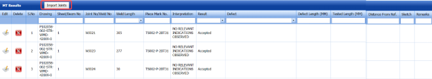
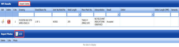
6.1.3 Import Joints
If you want to import joints for the updated RT results,
- Click
 (Import Joints button) in the RT Results See Fig 6.1.1.
The Joints window opens with a list of joints.

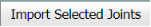
-
Select the joints you want to import.
-
Click
 (Import Selected Joints button).
The selected joints are imported for the respective RT results. Once you have imported the joints, you must add the marker results.


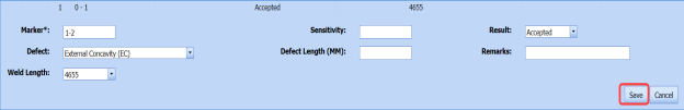
6.1.4 Add Marker Results
If you want to add marker results for the respective RT results,
- Click
 (Add icon) for the respective RT results.
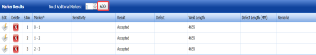
The Marker Results window opens.

-
If you want to add any additional markers,
-
-
Set the number in the No. of Additional Markers box by using up and down arrows.
-
Click
 (ADD button).
-
-
- If you want edit any existing marker results,
-
-
Click
 (Edit icon) in the Edit column for the respective marker results.
A new window opens to edit the marker results.
-
Click any box where you want to edit the details, and edit the marker results.
-
Click Save.
-
-
-
If you want delete any existing marker results, click (Delete icon) for the respective marker results.


6.1.5 Add Report Photos
If you want to add any report photos for the updated RT results,
- Click
 (ADD button) in the Report Photos box in the RT Results window. See Fig 6.1.1.

- Click
 (Browse button) to browse a photo stored in your computer.
 -
Click Upload.


The selected photo will be updated.
6.1.6 Attach a File into an RT Report
If you want to attach any file with any RT report listed in the RT Report page, follow the procedures given in the topic “Attach a file into a client master drawing” in the Client Master Drawing section.
6.1.7 Print an NDT – RT report
If you want to print an NDT - RT report, click  (print icon) provided in the Report column of the RT Report page. See Fig 6.1.
6.1.8 Edit Any RT Report
If you want to edit any existing RT report in the RT Report page, do the following,
- Click
 (Edit icon) in the Edit column for the respective RT report. See Fig 6.1.
A new window opens to edit the RT report.
- Click any box where you want to edit the details, and then edit the details in the respective box.
-
Click Save.

6.1.9 Export RT Report List
You can export a list of RT reports added in the RT Report page in the pdf and excel formats. To know how to export, see the topic, “Export Areas list” in the Area option.
6.1.10 Filter Any RT Report
If you want to filter any RT report, do one of the following, 
- If you want to filter any RT report based on the report number, enter the corresponding report number in the Report No box in the RT Report page, and then Click Search.
-
If you want to filter any RT report based on the request number, enter the corresponding request number in the Request No box in the RT Report page, and then Click Search.
- If you want to filter any RT report based on the drawing number, enter the corresponding drawing number in the Drawing No box in the RT Report page, and then Click Search.
6.2 Ultrasonic Testing (UT)
The UT method is one of the NDT inspection methods used for inspecting the materials in the structural project by using high frequency sound waves. Once the UT inspection request added in the NDT Inspection Request tab, you can add the UT inspection result details by using this Ultrasonic Testing (UT) tab. If you want to navigate Ultrasonic Testing (UT),
- Click the Ultrasonic Testing (UT) tab in the Structural menu.
The UT Report page opens.

Figure 6.2: UT Report page
6.2.1 Add an UT Report
If you want to add an UT report, do the following,
- Click
 (ADD button) in the UT Report page. See Fig 6.2.
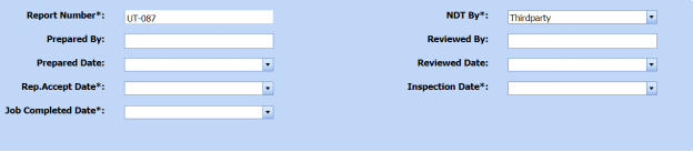
A new window opens to add an UT report.
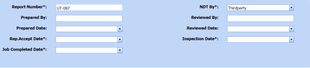
 Note: The fields notified with a symbol (*) are mandatory. You must enter the relevant details in that fields before saving.
 Tip: A report number for a new UT report will be updated automatically in the Report Number box.
 - In the NDT By box, select the creation of NDT whether by third party or internal from a drop-down list.
-
In the Request Number box, select an UT request number from a drop-down list.
-
In the Prepared By box, enter the name of a person who has prepared the UT report.
-
In the Prepared Date box, select the prepared date of the UT report.
- In the Reviewed By box, enter the name of a person who has reviewed the UT report.
-
In the Reviewed Date box, select the reviewed date of the UT report.
-
In the Approved By boxes, enter the name of a person who has approved the UT report.
-
In the Approved Date box, select the approved date of the UT report.
-
In the Rep. Accept Date box, select the report accept date.
-
In the Inspection Date box, select the date of inspection.
-
In the Job Done Report Number box, enter the report number of completed inspection job.
-
In the Job Completed Date box, select the completed date of the inspection job.
-
Click Save.


The UT report is successfully added. Once you have added the UT report, you must add UT results for the respective added UT report.
6.2.2 Add UT Results
If you want to add the UT results for the respective UT report, do the following,
- Click the respective added UT report in the UT Report page. See Fig 6.2.
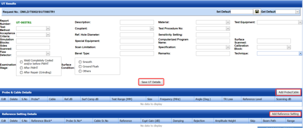
The UT Results window opens.

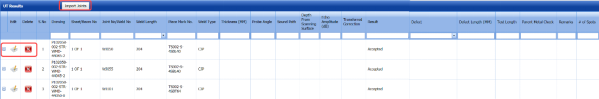
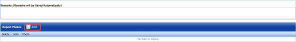
Figure 6.2.1: UT Results page
- In the Test Method box, select the test method from a drop-down list.
-
In the Description box, enter the description about the UT inspection.
-
In the Material box, select the material from a drop-down list.
-
In the Test Equipment box, select the test equipment from a drop-down list.
-
In the Acceptance Criteria box, select the acceptance criteria from a drop-down list.
-
In the Couplant box, select the couplant material from a drop-down list.
-
In the Test Procedure Number box, select the test procedure number from a drop-down list.
-
In the Simulation Blocks box, enter the detail of simulation blocks.
-
In the Ref. Hole Diameter box, enter the diameter value of the reference hole.
-
In the Sensitivity Setting box, enter the information about the sensitivity setting.
-
In the Sides Scanned box, enter the details of the sides that are scanned.
-
In the Special Equipment box, enter the name of the special equipment if any.
-
In the Computerized Program Name box, enter the computerized program name.
-
In the Surface Scanned box, the details of the surfaces that are scanned.
-
In the Flaw Detector box, select a flaw detector from a drop-down list.
-
In the Scan Limitation box, enter the limitation range of scanning.
-
In the Bevel Type box, enter the type of the bevel.
-
In the Specification box, select the specification from a drop-down list.
-
In the Calibration Block box, select the calibration block from a drop-down list.
-
In the Remarks box, enter your remarks if any.
-
In the Technique box, select the technique from a drop-down list.
-
In the Examination Stage box, select the examination stage from the specified options.
-
In the Surface Condition box, select the surface condition from the specified options.
-
Click Save UT Details.


The UT results are successfully updated. Once you have updated the UT results, you must add the probe and cable details for the UT inspection.
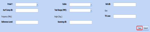
6.2.3 Add Probe and Cable details
If you want to add probe and cable details for the updated UT results,
- Click
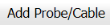 (Add Probe/ Cable button) in the Probe& Cable Details window. See Fig 6.2.1.
A new window opens to add the probe and cable details.

- In the Probe box, select a probe from a drop-down list.
-
In the Cable box, select a cable from a drop-down list.
-
In the Ref. dB box, enter the reference decibel range.
-
In the Surf Comp dB box, enter the decibel range of the surface component.
-
In the Test Range (MM) box, enter the test range in millimeters.
-
In the Reference Level box, enter the reference level detail.
-
In the Scanning dB box, enter the scanning decibel range.
-
In the TR Loss box, enter the transmission loss detail.
-
Click Save.

The probe and cable details are successfully added. Once you have added the probe and cable details, you must add the reference setting details.
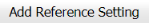
6.2.4 Add Reference Setting details
If you want to add the reference setting details for the updated UT results,
- Click
 (Add Reference Setting button) in the Reference Setting Details See Fig 6.2.1.
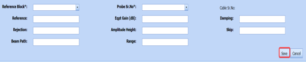
A new window opens to add the reference setting details.

-
In the Reference Block box, select the reference block from a drop-down list.
-
In the Probe Sr. No box, select the serial number of the probe from a drop-down list.
-
In the Reference box, enter the reference detail.
-
In the Eqpt Gain (dB) box, enter the equipment gain in decibels.
-
In the Damping box, enter the damping ratio.
-
In the Rejection box, enter the rejection detail.
-
In the Amplitude Height box, enter the amplitude height range.
-
In the Skip box, enter the skip detail.
-
In the Beam Path box, enter the beam path detail.
-
In the Range box, enter the range detail.
-
Click Save.
The reference setting details are successfully added. Once you have added the reference setting details, you must import joints for the updated UT results.
6.2.5 Import Joints for UT
If you want to import joints for the updated UT results,
- Click
 (Import Joints button) in the UT Results See Fig 6.2.1.
The Joints window opens with a list of joints.

- Select the joints you want to import.
-
Click
 (Import Selected Joints button).


The selected joints are imported for the respective UT results. Once you have imported the joints, you must add the UT detail results.
6.2.6 Add UT Results
If you want to add UT detail results for the respective UT results,
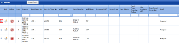
- Click
 (Add icon) for the respective UT results.
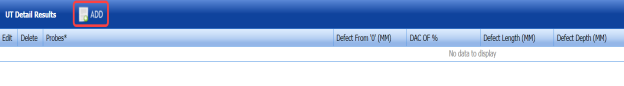
The UT Detail Results window opens.

-
Click
 (ADD button) in the UT Detail Results window.
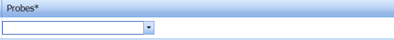
A new window opens in the Probes column.

-
Select the probe from a drop-down list.
-
Enter other details in the respective columns.
-
Click Save.


6.2.7 Add Report Photos
If you want to add any report photos for the updated UT results,
- Click
 (ADD button) in the Report Photos box in the UT Results See Fig 6.2.1.

-
Click
 (Browse button) to browse a photo stored in your computer.
 - Click Upload.


The selected photo will be updated.
6.2.8 Attach a File into an UT Report
If you want to attach any file with any UT report listed in the UT Report page, follow the procedures given in the topic “Attach a file into a client master drawing” in the Client Master Drawing section.
6.2.9 Print an NDT – UT Report
If you want to print an NDT - UT report, click (print icon) provided in the Report column of the UT Report page. See Fig 6.2.
6.2.10 Edit Any UT report
If you want to edit any existing UT report in the UT Report page, do the following,
- Click
 (Edit icon) in the Edit column for the respective UT report. See Fig 6.2.
A new window opens to edit the UT report.
- Click any box where you want to edit the details, and then edit the details in the respective box.
-
Click Save.

6.2.11 Export UT Report List
You can export a list of UT reports added in the UT Report page in the pdf and excel formats. To know how to export, see the topic, “Export Areas list” in the Area option.
6.2.12 Filter Any UT Report
If you want to filter any UT report, do one of the following,
- If you want to filter any UT report based on the report number, enter the corresponding report number in the Report No box in the UT Report page, and then Click Search.
- If you want to filter any UT report based on the request number, enter the corresponding request number in the Request No box in the UT Report page, and then Click Search.
If you want to filter any UT report based on the drawing number, enter the corresponding drawing number in the Drawing No box in the UT Report page, and then Click Search.
6.3 Dye Penetrant Testing (DPT)
The DPT method is one of the oldest and simplest NDT inspection methods used for inspecting the materials in the structural project by using ultraviolet or white light, depending on the type of dye used - fluorescent or non fluorescent (visible). PT also called liquid penetrate inspection (LPI) or penetrant testing (PT).
Once the UT inspection request added in the NDT Inspection Request tab, you can add the UT inspection result details by using this Dye Penetrant Testing (DPT) tab. If you want to navigate Dye Penetrant Testing (DPT),
- Click the Dye Penetrant Testing (DPT) tab in the Structural menu.
The PT Report page opens.
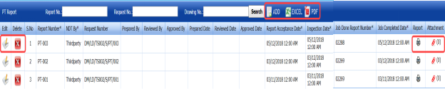
Figure 6.3: PT Report page
6.3.1 Add a DPT Report
If you want to add a DPT report, do the following,
- Click
 (ADD button) in the PT Report page. See Fig 6.3.
A new window opens to add an PT report.

 Note: The fields notified with a symbol (*) are mandatory. You must enter the relevant details in that fields before saving.
 Tip: A report number for a new PT report will be updated automatically in the Report Number box.
 -
In the NDT By box, select the creation of NDT whether by third party or internal from a drop-down list.
-
In the Request Number box, select an PT request number from a drop-down list.
-
In the Prepared By box, enter the name of a person who has prepared the PT report.
-
In the Prepared Date box, select the prepared date of the PT report.
-
In the Reviewed By box, enter the name of a person who has reviewed the PT report.
-
In the Reviewed Date box, select the reviewed date of the PT report.
-
In the Approved By boxes, enter the name of a person who has approved the PT report.
-
In the Approved Date box, select the approved date of the PT report.
-
In the Rep. Accept Date box, select the report accept date.
-
In the Inspection Date box, select the date of inspection.
-
In the Job Done Report Number box, enter the report number of completed inspection job.
-
In the Job Completed Date box, select the completed date of the inspection job.
-
Click Save.


The PT report is successfully added. Once you have added the PT report, you must add PT results for the respective added PT report.
6.3.2 Add DPT Results
If you want to add the DPT results for the respective PT report, do the following,
- Click the respective added PT report in the PT Report page. See Fig 6.3.
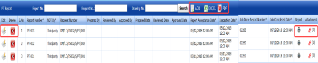
The DPT Results window opens.


Figure 6.3.1: DPT Results page
- In the Light Source box, enter the light source detail.
-
In the Description box, enter the description.
-
In the Test Procedure box, select the test procedure from a drop-down list.
-
In the Test Method box, select the test method from a drop-down list.
-
In the Acceptance Criteria box, select the acceptance criteria from a drop-down list.
-
In the Surface Condition box, enter the condition of the surface.
-
In the Dwell Time box, enter dwell time range.
-
In the Surface Temperature box, enter the surface temperature value.
-
In the Cleaner box, select the cleaner from a drop-down list.
-
In the Penetrant box, select the penetrant from a drop-down list.
-
In the Developer box, select the developer from a drop-down list.
-
In the Material Specification box, enter the material specification.
-
In the Material Thickness box, enter the material thickness value.
-
In the Development Time box, enter the time for development.
-
In the Welding Process box, enter the type of welding process.
-
In the Code box, enter the code detail.
-
In the Examination Stage box, select the examination stage from the specified options.
-
In the Item Tested box, select the tested items from the specified options.
-
In the Inspection Method box, select the inspection method from the specified options.
-
In the Material box, select the material from a drop-down list.
-
In the Remarks box, enter your remarks if any.
-
Click Save DPT Details.

The DPT results are successfully updated. Once you have updated the DPT results, you must import joints added for the DPT inspection results.
6.3.3 Import Joints for DPT
If you want to import joints for the updated DPT results,
- Click
 (Import Joints button) in the DPT Results window. See Fig 6.3.1.
The Joints window opens with a list of joints.

-
Select the joints you want to import.
-
Click
 (Import Selected Joints button).
The selected joints are imported for the respective DPT results.


6.3.4 Add Report Photos
If you want to add any report photos for the updated DPT results,
- Click
 (ADD button) in the Report Photos box in the DPT Results window. See Fig 6.3.1.

-
Click
 (Browse button) to browse a photo stored in your computer.
 -
Click Upload.
The selected photo will be updated.


6.3.5 Attach a File into a DPT Report
If you want to attach any file with any DPT report listed in the PT Report page, follow the procedures given in the topic “Attach a file into a client master drawing” in the Client Master Drawing section.
6.3.6 Print an NDT – DPT report
If you want to print an NDT - PT report, click  (print icon) provided in the Report column of the PT Report page. See Fig 6.3.
6.3.7 Edit Any DPT report
If you want to edit any existing DPT report in the RT Report page, do the following,
- Click
 (Edit icon) in the Edit column for the respective DPT report. See Fig 6.3.
A new window opens to edit the DPT report.
-
Click any box where you want to edit the details, and then edit the details in the respective box.
-
Click Save.

6.3.8 Export DPT Report List
You can export a list of DPT reports added in the PT Report page in the pdf and excel formats. To know how to export, see the topic, “Export Areas list” in the Area option.
6.3.9 Filter Any DPT Report
If you want to filter any DPT report, do one of the following,
- If you want to filter any DPT report based on the report number, enter the corresponding report number in the Report No box in the PT Report page, and then Click Search.
-
If you want to filter any DPT report based on the report number, enter the corresponding report number in the Report No box in the PT Report page, and then Click Search.
If you want to filter any DPT report based on the report number, enter the corresponding report number in the Report No box in the PT Report page, and then Click Search.
6.4 PT After Load Test
The PT After Load Test tab in the Structural menu helps you to add PT results while performing the PT inspection after completing the load test.
Once the PT after load test inspection request added in the NDT Inspection Request tab, you can add the PT result details by using this PT After Load Test tab. If you want to navigate PT After Load Test,
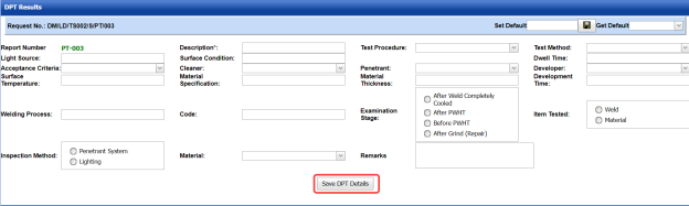
- Click the PT After Load Test tab in the Structural menu. The PT After Load Test Report page opens.

Figure 6.4: PT After Load Test Report page
6.4.1 Add a PT after load test report
If you want to add a PT after load test report, do the following,
- Click
 (ADD button) in the PT After Load Test Report page. See Fig 6.4.
A new window opens to add a PT after load test report.

 Note: The fields notified with a symbol (*) are mandatory. You must enter the relevant details in that fields before saving.
 Tip: A report number for a new PT report will be updated automatically in the Report Number box.
 - In the NDT By box, select the creation of NDT whether by third party or internal from a drop-down list.
-
In the Request Number box, select an PT request number after load test from a drop-down list.
-
In the Prepared By box, enter the name of a person who has prepared the PT report after load test.
- In the Prepared Date box, select the prepared date of the PT report after load test.
- In the Reviewed By box, enter the name of a person who has reviewed the PT report after load test.
- In the Reviewed Date box, select the reviewed date of the PT report after load test.
- In the Approved By boxes, enter the name of a person who has approved the PT report after load test.
- In the Approved Date box, select the approved date of the PT report after load test.
-
In the Rep. Accept Date box, select the report accept date.
-
In the Inspection Date box, select the date of inspection.
-
In the Job Done Report Number box, enter the report number of completed inspection job.
-
In the Job Completed Date box, select the completed date of the inspection job.
-
Click Save.


The PT report after load test is successfully added. Once you have added the PT report, you must add PT results for the respective PT report.
6.4.2 Add PT Results
If you want to add the PT results for the respective PT report after load test, do the following,
- Click the respective added PT report in the PT After Load Test Report page. See Fig 6.4.
The PT After Load Test Results page opens.
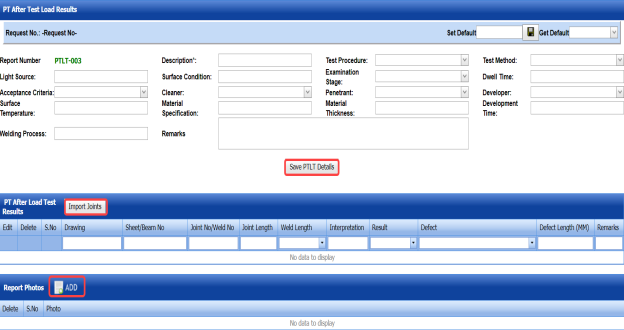
Figure 6.4.1: PT After Load Test Results page
-
In the Light Source box, enter the light source detail.
-
In the Description box, enter the description.
-
In the Test Procedure box, select the test procedure from a drop-down list.
-
In the Test Method box, select the test method from a drop-down list.
-
In the Acceptance Criteria box, select the acceptance criteria from a drop-down list.
-
In the Surface Condition box, enter the condition of the surface.
-
In the Dwell Time box, enter dwell time range.
-
In the Surface Temperature box, enter the surface temperature value.
-
In the Cleaner box, select the cleaner from a drop-down list.
-
In the Penetrant box, select the penetrant from a drop-down list.
-
In the Developer box, select the developer from a drop-down list.
-
In the Material Specification box, enter the material specification.
-
In the Material Thickness box, enter the material thickness value.
-
In the Development Time box, enter the time for development.
-
In the Welding Process box, enter the type of welding process.
-
In the Examination Stage box, select the examination stage from the specified options.
-
In the Remarks box, enter your remarks if any.
-
Click Save PTLT Details.

The PT after load test results are successfully updated. Once you have updated the PT results, you must import joints added for the PT after load test inspection results.
6.4.3 Import Joints for PT After Load Test
If you want to import joints for the updated PT after load test results,
- Click
 (Import Joints button) in the PT After Load Test Results window. See Fig 6.4.1.
The Joints window opens with a list of joints.

-
Select the joints you want to import.
-
Click
 (Import Selected Joints button).
The selected joints are imported for the respective DPT results.


6.4.4 Add Report Photos
If you want to add any report photos for the updated PT after load test results,
- Click
 (ADD button) in the Report Photos box in the PT After Load Test Results See Fig 6.4.1.

-
Click
 (Browse button) to browse a photo stored in your computer.
 -
Click Upload.
The selected photo will be updated.


6.4.5 Attach a file into a PT After Load Test Report
If you want to attach any file with any PT report listed in the PT After Load Test Report page, follow the procedures given in the topic “Attach a file into a client master drawing” in the Client Master Drawing section.
6.4.6 Print an NDT – PT After Load Test Report
If you want to print an NDT – PT after load test report, click (print icon) provided in the Report column of the PT After Load Test Report page. See Fig 6.4.
6.4.7 Edit Any PT After Load Test Report
If you want to edit any existing PT report in the PT After Load Test Report page, do the following,
- Click
 (Edit icon) in the Edit column for the respective PT report. See Fig 6.4.
A new window opens to edit the PT report.
-
Click any box where you want to edit the details, and then edit the details in the respective box.
-
Click Save.

6.4.8 Export PT after load test report list
You can export a list of PT reports added in the PT After Load Test Report page in the pdf and excel formats. To know how to export, see the topic, “Export Areas list” in the Area option.
6.4.9 Filter Any PT After Load Test Report
If you want to filter any PT report, do one of the following,
-
If you want to filter any PT report based on the report number, enter the corresponding report number in the Report No box in the PT After Load Test Report page, and then Click Search.
-
If you want to filter any PT report based on the request number, enter the corresponding request number in the Request No box in the PT After Load Test Report page, and then Click Search.
If you want to filter any PT report based on the drawing number, enter the corresponding drawing number in the Drawing No box in the PT After Load Test Report page, and then Click Search.
6.5 Magnetic Particle Testing (MPT)
MPT also referred to as Magnetic Particle Inspection is one of the NDT inspection methods used to detect defects or discontinuities such as cracks, at or near the surface in ferromagnetic metals such as iron, steel, nickel, cobalt and so on.
Once the MPT inspection request added in the NDT Inspection Request tab, you can add the MPT inspection result details by using this Magnetic Particle Testing (MPT) tab. If you want to navigate Magnetic Particle Testing (MPT),
- Click the Magnetic Particle Testing (MPT) tab in the Structural menu.
The MT Report page opens.
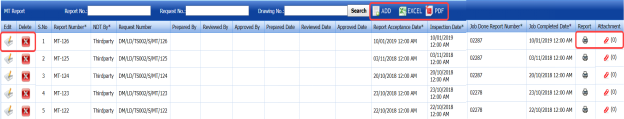
Figure 6.5: MT Report page

6.5.1 Add an MPT Report
If you want to add an MPT report, do the following,
- Click
 (ADD button) in the MT Report page. See Fig 6.5.
A new window opens to add an MPT report.

 Note: The fields notified with a symbol (*) are mandatory. You must enter the relevant details in that fields before saving.
 Tip: A report number for a new MPT report will be updated automatically in the Report Number box.
 -
In the NDT By box, select the creation of NDT whether by third party or internal from a drop-down list.
-
In the Request Number box, select an MPT request number from a drop-down list.
-
In the Prepared By box, enter the name of a person who has prepared the MPT report.
-
In the Prepared Date box, select the prepared date of the MPT report.
-
In the Reviewed By box, enter the name of a person who has reviewed the MPT report.
-
In the Reviewed Date box, select the reviewed date of the MPT report.
-
In the Approved By boxes, enter the name of a person who has approved the MPT report.
-
In the Approved Date box, select the approved date of the MPT report.
-
In the Rep. Accept Date box, select the report accept date.
-
In the Inspection Date box, select the date of inspection.
-
In the Job Done Report Number box, enter the report number of completed inspection job.
-
In the Job Completed Date box, select the completed date of the inspection job.
-
Click Save.


The MPT report is successfully added. Once you have added the MPT report, you must add MPT results for the respective MPT report.
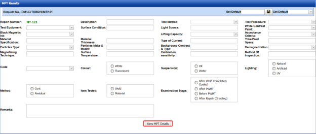
6.5.2 Add MPT Results
If you want to add the MPT results for the respective MPT report, do the following,
- Click the respective MPT report in the MT Report page. See Fig 6.5.
The MPT Results window opens.

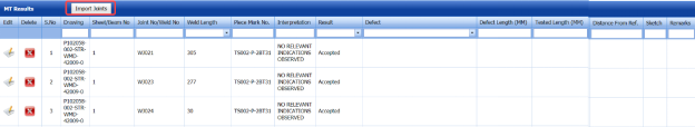

Figure 6.5.1: MPT Results page
- In the Test Equipment box, select the test equipment from a drop-down list.
-
In the Description box, enter the description.
-
In the Test Procedure box, select the test procedure from a drop-down list.
-
In the Test Method box, select the test method from a drop-down list.
-
In the Black Magnetic Ink box, select the type of black magnetic ink from a drop-down list.
-
In the Surface Condition box, enter the condition of the surface.
-
In the Light Source box, enter the light source detail.
-
In the White Contrast Paint box, select the type of white contrast paint.
-
In the Material Specification box, enter the material specification.
-
In the Material Thickness box, enter the material thickness value.
-
In the Type of Current box, enter the type of current.
-
In the Lifting Capacity box, select the lifting capacity value.
-
In the Acceptance Criteria box, select the acceptance criteria from a drop-down list.
-
In the Yoke/ Prod Space box, enter the relevant information.
-
In the Particles Type box, select the type of particles from a drop-down list.
-
In the Particles Make & model box, enter the model of the particle including made of materials.
-
In the Background Contrast & Type box, enter the type of background including contrast range.
- In the Demagnetization box, if you want demagnetization select Yes otherwise select No.
-
In the Magnetizing Technique box, enter the magnetizing technique.
-
In the Surface Temperature box, enter the surface temperature value.
-
In the Calibration Sensitivity box, enter the calibration sensitivity range.
-
In the Method of Inspection box, enter the inspection method.
-
In the Code box, enter the code detail.
-
In the Color box, select any color from the specified options.
-
In the Suspension box, select any suspension liquid from the specified options.
-
In the Lighting box, select any lighting from the specified options.
-
In the Method box, select any method from the specified options.
-
In the Item Tested box, select the tested items from the specified options.
-
In the Examination Stage box, select the examination stage from the specified options.
-
Click Save MPT Details.

The MPT results are successfully updated. Once you have updated the MPT results, you must import joints added for the MPT inspection results.
6.5.3 Import Joints for MPT
If you want to import joints for the updated MPT results,
- Click
 (Import Joints button) in the MPT Results See Fig 6.5.1.
The Joints window opens with a list of joints.

-
Select the joints you want to import.
-
Click
 (Import Selected Joints button).
The selected joints are imported for the respective MPT results.


6.5.4 Add Report Photos
If you want to add any report photos for the updated MPT results,
- Click
 (ADD button) in the Report Photos box in the MPT Results window. See Fig 6.5.1.

-
Click
 (Browse button) to browse a photo stored in your computer.
 -
Click Upload.


The selected photo will be updated.
6.5.5 Attach a File into an MPT Report
If you want to attach any file with any MPT report listed in the MT Report page, follow the procedures given in the topic “Attach a file into a client master drawing” in the Client Master Drawing section.
6.5.6 Print an NDT – MPT Report
If you want to print an NDT - MPT report, click  (print icon) provided in the Report column of the MT Report page. See Fig 6.5.
6.5.7 Edit Any MPT Report
If you want to edit any existing MPT report in the MT Report page, do the following,
- Click
 (Edit icon) in the Edit column for the respective MPT report. See Fig 6.5.
A new window opens to edit the MPT report.
- Click any box where you want to edit the details, and then edit the details in the respective box.
-
Click Save.

6.5.8 Export MPT Report List
You can export a list of MPT reports added in the MT Report page in the pdf and excel formats. To know how to export, see the topic, “Export Areas list” in the Area option.
6.5.9 Filter Any MPT Report
If you want to filter any MPT report, do one of the following,
- If you want to filter any MPT report based on the report number, enter the corresponding report number in the Report No box in the MT Report page, and then Click Search.
- If you want to filter any MPT report based on the report number, enter the corresponding report number in the Report No box in the MT Report page, and then Click Search.
If you want to filter any MPT report based on the drawing number, enter the corresponding drawing number in the Drawing No box in the MT Report page, and then Click Search.
6.6 MPI After Load Test (MPI)
The MPI After Load Test (MPI) tab in the Structural menu helps you to add MPI results while performing the MPI inspection after completing the load test.
Once the MPI after load test inspection request added in the NDT Inspection Request tab, you can add the MPI result details by using this MPI After Load Test (MPI) tab. If you want to navigate MPI After Load Test (MPI),
- Click the MPI After Load Test (MPI) tab in the Structural menu.
The MPI Report page opens.
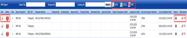
Figure 6.6: MPI Report page

3.6.1 Add an MPI After Load Test Report
If you want to add an MPI after load test report, do the following,
- Click
 (ADD button) in the MPI Report page. See Fig 6.6.
A new window opens to add an MPI after load test report.
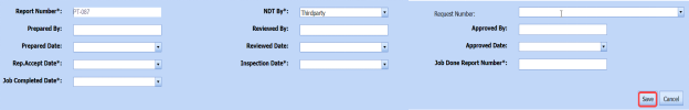
 Note: The fields notified with a symbol (*) are mandatory. You must enter the relevant details in that fields before saving.
 Tip: A report number for a new MPI report will be updated automatically in the Report Number box.
 - In the NDT By box, select the creation of NDT whether by third party or internal from a drop-down list.
-
In the Request Number box, select an MPI request number after load test from a drop-down list.
- In the Prepared By box, enter the name of a person who has prepared the MPI report after load test.
- In the Prepared Date box, select the prepared date of the MPI report after load test.
- In the Reviewed By box, enter the name of a person who has reviewed the MPI report after load test.
- In the Reviewed Date box, select the reviewed date of the MPI report after load test.
- In the Approved By boxes, enter the name of a person who has approved the MPI report after load test.
- In the Approved Date box, select the approved date of the MPI report after load test.
-
In the Rep. Accept Date box, select the report accept date.
-
In the Inspection Date box, select the date of inspection.
-
In the Job Done Report Number box, enter the report number of completed inspection job.
-
In the Job Completed Date box, select the completed date of the inspection job.
-
Click Save.


The MPI report after load test is successfully added. Once you have added the MPI report, you must add MPI results for the respective MPI report.
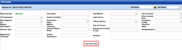
6.6.2 Add MPI Results
If you want to add the MPI results for the respective MPI report after load test, do the following,
- Click the respective MPI report in the MPI Report page. See Fig 6.6.
The MPI Results page opens.


Figure 6.6.1: MPI Results page
-
In the Test Equipment box, select the test equipment from a drop-down list.
-
In the Description box, enter the description.
-
In the Test Procedure box, select the test procedure from a drop-down list.
-
In the Test Method box, select the test method from a drop-down list.
-
In the Black Magnetic Ink box, select the type of black magnetic ink from a drop-down list.
-
In the Surface Condition box, enter the condition of the surface.
-
In the Light Source box, enter the light source detail.
-
In the White Contrast Paint box, select the type of white contrast paint.
-
In the Material Specification box, enter the material specification.
-
In the Material Thickness box, enter the material thickness value.
-
In the Type of Current box, enter the type of current.
-
In the Lifting Capacity box, select the lifting capacity value.
-
In the Acceptance Criteria box, select the acceptance criteria from a drop-down list.
-
In the Yoke/ Prod Space box, enter the relevant information.
-
In the Particles Type box, select the type of particles from a drop-down list.
-
In the Particles Make & model box, enter the model of the particle including made of materials.
-
In the Background Contrast & Type box, enter the type of background including contrast range.
-
In the Demagnetization box, if you want demagnetization select Yes otherwise select No.
-
In the Magnetizing Technique box, enter the magnetizing technique.
-
In the Surface Temperature box, enter the surface temperature value.
-
In the Remarks box, enter your remarks if any.
-
Click Save MPI Details.
The MPI results are successfully updated. Once you have updated the MPI results, you must import joints added for the MPI inspection results.
6.6.3 Import Joints for MPI
If you want to import joints for the updated MPI results,
- Click
 (Import Joints button) in the MPI Results See Fig 6.6.1.
The Joints window opens with a list of joints.

-
Select the joints you want to import.
-
Click
 (Import Selected Joints button).
The selected joints are imported for the respective MPI results.


6.6.4 Add Report Photos
If you want to add any report photos for the updated MPI results,
- Click
 (ADD button) in the Report Photos box in the MPI Results See Fig 6.6.1.

-
Click
 (Browse button) to browse a photo stored in your computer.
 -
Click Upload.
The selected photo will be updated.


6.6.5 Attach a File into an MPI Report
If you want to attach any file with any MPI report listed in the MPI Report page, follow the procedures given in the topic “Attach a file into a client master drawing” in the Client Master Drawing section.
6.6.6 Print an NDT – MPI Report
If you want to print an NDT - MPI report, click  (print icon) provided in the Report column of the MPI Report page. See Fig 6.6.
6.6.7 Edit Any MPI Report
If you want to edit any existing MPI report in the MPI Report page, do the following,
- Click
 (Edit icon) in the Edit column for the respective MPI report. See Fig 6.6.
A new window opens to edit the MPI report.
-
Click any box where you want to edit the details, and then edit the details in the respective box.
-
Click Save.

6.6.8 Export MPI Report List
You can export a list of MPI reports added in the MPI Report page in the pdf and excel formats. To know how to export, see the topic, “Export Areas list” in the Area option.
6.6.9 Filter any MPI report
If you want to filter any MPI report, do one of the following,
- If you want to filter any MPI report based on the report number, enter the corresponding report number in the Report No box in the MPI Report page, and then Click Search.
- If you want to filter any MPI report based on the request number, enter the corresponding request number in the Request No box in the MPI Report page, and then Click Search.
- If you want to filter any MPI report based on the drawing number, enter the corresponding drawing number in the Drawing No box in the MPI Report page, and then Click Search.
6.7 PWHT
The PWHT tab in the Structural menu helps you to add a PWHT report after completing the PWHT inspection process. If you want to add a PWHT report, do the following,
Once the RFI request for PWHT added using the RFI Request for PWHT tab, you can add the PWHT result details by using this PWHT tab. If you want to navigate PWHT,
- Click the PWHT tab in the Structural menu.
The PWHT Report page opens.

Figure 6.7: PWHT Report page
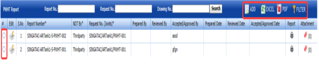
9.7.1 Add a PWHT Report
If you want to add a PWHT report, do the following,
- Click
 (ADD button) in the PWHT Report page. See Fig 6.7.
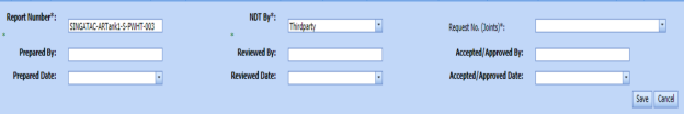
A new window opens to add a PWHT report.

 Note: The fields notified with a symbol (*) are mandatory. You must enter the relevant details in that fields before saving.
 Tip: A report number for a new PWHT report will be updated automatically in the Report Number box.
 -
In the NDT By box, select the creation of NDT whether by third party or internal from a drop-down list.
-
In the Request Number box, select an RFI request for PWHT number from a drop-down list.
-
In the Prepared By box, enter the name of a person who has prepared the PWHT report.
-
In the Prepared Date box, select the prepared date of the PWHT report.
-
In the Reviewed By box, enter the name of a person who has reviewed the PWHT report.
-
In the Reviewed Date box, select the reviewed date of the PWHT report.
- In the Accepted/ Approved By boxes, enter the name of a person who has approved the PWHT report.
-
In the Accepted/ Approved Date box, select the approved date of the PWHT report.
-
Click Save.


The PWHT report is successfully added. Once you have added the PWHT report, you must add PWHT result details for the respective PWHT report.
6.7.2 Add PWHT Results
If you want to add the PWHT results for the respective PWHT report, do the following,
- Click the respective PWHT report in the PWHT Report page. See Fig 6.7.
The PWHT Results page opens.

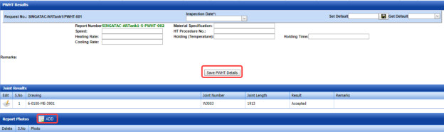
Figure 6.7.1: PWHT Results page
- In the Inspection Date box, select the inspection date.
-
In the Material Specification box, enter the specification for the material.
-
In the Speed box, enter the speed range.
-
In the HT Procedure No box, select the HT procedure number.
-
In the Heating Rate box, enter the heating rate value.
-
In the Holding (Temperature) box, enter the holding temperature.
-
In the Holding Time box, enter the holding time value.
-
In the Cooling Rate box, enter the cooling rate value.
-
In the Remarks box, enter your remarks if any.
-
Click Save PWHT Details.
The PWHT results are successfully updated. Once you have updated the PWHT results, you can edit the joints added for the PWHT inspection results in the Joint Results window.
6.7.3 Add Report Photos
If you want to add any report photos for the updated PWHT results,
- Click
 (ADD button) in the Report Photos box in the PWHT Results See Fig 6.7.1.

-
Click
 (Browse button) to browse a photo stored in your computer.
 -
Click Upload.


The selected photo will be updated.
6.7.4 Attach a File into a PWHT Report
If you want to attach any file with any PWHT report listed in the PWHT Report page, follow the procedures given in the topic “Attach a file into a client master drawing” in the Client Master Drawing section.
6.7.5 Print a PWHT Report
If you want to print a PWHT report, click  (print icon) provided in the Report column of the PWHT Report page. See Fig 6.7.
6.7.6 Edit Any PWHT Report
If you want to edit any existing PWHT report in the PWHT Report page, do the following,
- Click
 (Edit icon) in the Edit column for the respective PWHT report. See Fig 6.7.
A new window opens to edit the PWHT report.
- Click any box where you want to edit the details, and then edit the details in the respective box.
-
Click Save.

6.7.7 Export PWHT Report List
You can export a list of PWHT reports added in the PWHT Report page in the pdf and excel formats. To know how to export, see the topic, “Export Areas list” in the Area option.
6.7.8 Filter Any PWHT Report
If you want to filter any PWHT report, use  (FILTER button) in the PWHT Report page, See Fig 6.7 or do one of the following,
- If you want to filter any PWHT report based on the report number, enter the corresponding report number in the Report No box in the PWHT Report page, and then Click Search.
- If you want to filter any PWHT report based on the request number, enter the corresponding request number in the Request No box in the PWHT Report page, and then Click Search.
-
If you want to filter any PWHT report based on the drawing number, enter the corresponding drawing number in the Drawing No box in the PWHT Report page, and then Click Search.
6.8 Hydrostatic Report
Hydrostatic testing is a type of pressure test where the materials are tested for strength and leaks. The Hydrostatic Report tab in the Structural menu helps you to add a hydrostatic pressure test report after completing the hydrostatic testing in the structural project.
If you want to add a hydrostatic pressure test report, do the following,
- Click the Hydrostatic Report Tab.
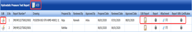
The Hydrostatic Pressure Test Report page opens.

Figure 6.8: Hydrostatic Pressure Test Report page
6.8.1 Add a Hydrostatic Pressure Test Report
If you want to add a hydrostatic pressure test report,
- Click
 (ADD button) in the Hydrostatic Pressure Test Report page. See Fig 6.8.
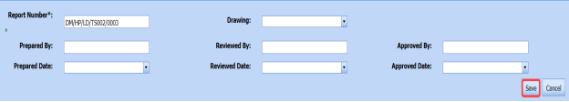
A new window opens to add a hydrostatic pressure test report.
 Note: The fields notified with a symbol (*) are mandatory. You must enter the relevant details in that fields before saving.
 Tip: A report number for a new hydrostatic pressure test report will be updated automatically in the Report Number box.
 -
In the Drawing box, select the drawing from a drop-down list.
- In the Prepared By box, enter the name of a person who has prepared the hydrostatic pressure test report.
-
In the Prepared Date box, select the preparation date of the report.
- In the Reviewed By box, enter the name of a person who has reviewed the hydrostatic pressure test report.
-
In the Reviewed Date box, select the reviewed date of the report.
-
In the Approved By box, enter the name of a person who has approved the hydrostatic pressure test report.
-
In the Approved Date box, select the approved date of the report.
-
Click Save.


The hydrostatic pressure test report is successfully added. Once you have added the hydrostatic pressure test report, you must add the pressure test result details for the added report.
6.8.2 Add Pressure Test Results for an Added Hydrostatic Pressure Test Report
If you want to add the details of pressure test results for the added hydrostatic pressure test report, do the following,
- Click
 (Edit icon) in the Edit Report column of the Hydrostatic Pressure Test Report See Fig 6.8.
Multiple windows open.

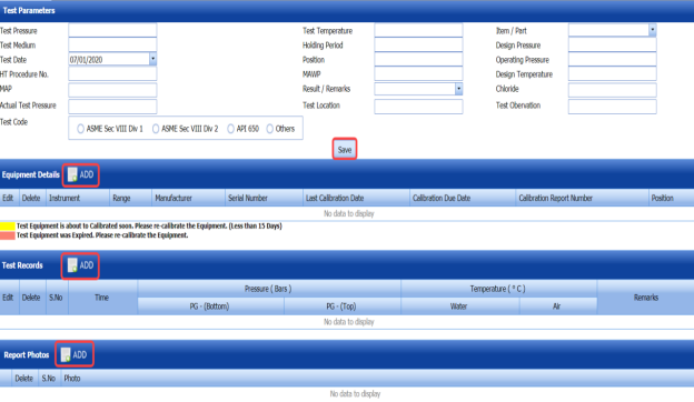
Figure 6.8.1: Pressure test results page
-
If you want to add test parameters, do the following steps,
-
-
Navigate to the Test Parameters window. See Fig 6.8.1.
-
In the Test Pressure box, enter the test pressure value.
-
In the Test Temperature box, enter the test temperature value.
-
In the Item/Part box, select any item/part from a drop-down list.
-
In the Test Medium box, enter the test medium information.
-
In the Holding Period box, enter the holding period value.
-
In the Design Pressure box, enter the design pressure value.
-
In the Test Date box, select the test date.
-
In the Position box, enter the position detail.
-
In the Operating Pressure box, enter the operating pressure value.
-
In the Hydrostatic Test (HT) Procedure No box, enter the hydrostatic test procedure number.
-
In the Maximum Allowable Working Pressure (MAWP) box, enter the maximum allowable working pressure value.
- In the Design Temperature box, enter the design temperature value.
- In the Maximum Allowable Pressure (MAP)box, enter the maximum allowable pressure value.
- In the Results/ Remarks box, select the result from a drop-down list.
-
In the Chloride box, enter the chloride value.
-
In the Actual Test Pressure box, enter the actual test pressure value.
-
In the Test Location box, enter the test location detail.
-
In the Test Observation box, enter the test observation detail.
-
In the Test Code box, select the test code from the specified options.
-
Click Save.
The test parameters are successfully added.
-
-
- If you want to add equipment details, do the following steps,
-
-
Navigate to the Equipment Details window. See Fig 6.8.1.
- In the Conducted By box, select any one option whether internal or external from a drop-down list.
-
In the Position box, select the position from a drop-down list.
-
In the Equipment Details box, select the equipment from a drop-down list.
-
Click Save.
The equipment details are successfully added.
-
-
-
If you want to add test record, do the following,
-
-
Navigate to the Test Records window. See Fig 6.8.1.
-
In the Time box, enter the time duration of testing.
-
In the PG- Bottom box, enter the pressure value in the bottom of the bars.
-
In the PG- Top box, enter the pressure value in the top of the bars.
-
In the Water box, enter the temperature of the water.
-
In the Air box, enter the temperature of the air.
-
In the Remarks box, enter your remarks if any.
-
Click Save.
The test records are added successfully.
-
-
-
If you want to add report photos, do the following,
-
-
Navigate to the Report Photos window. See Fig 6.8.1.
-
Click
 (ADD button) in the Report Photos window.
- Click (Browse button) to browse a photo stored in your computer.
-
Click Upload.
The selected photo will be updated.
-
-


6.8.3 Print a Hydrostatic Pressure Test Report
If you want to print a hydrostatic pressure test report, click (print icon) provided in the Report column of the Hydrostatic Pressure Test Report page. See Fig 6.8.
6.8.4 Print a Hydrostatic Pressure Test Report with Certificates
If you want to print a hydrostatic pressure test report with certificates, click  (print icon) provided in the Report with Certificates column of the Hydrostatic Pressure Test Report page. See Fig 6.8.
6.8.5 Attach a File into a Hydrostatic Pressure Test Report
If you want to attach any file with any hydrostatic pressure test report listed in the Hydrostatic Pressure Test Report page, follow the procedures given in the topic “Attach a file into a client master drawing” in the Client Master Drawing section.
6.8.6 Edit Any Hydrostatic Pressure Test Report
If you want to edit any existing hydrostatic pressure test report in the Hydrostatic Pressure Test Report page, do the following,
-
Click
 (Edit icon) in the Edit column for the respective hydrostatic pressure test report. See Fig 6.8.
A new window opens to edit the hydrostatic pressure test report.
- Click any box where you want to edit the details, and then edit the details in the respective box.
-
Click Save.

6.9 Vacuum Test
Vacuum test performed to check for the existence of any leak in the materials utilized in the Structural project. The Vacuum Test tab in the Structural menu helps you to add a vacuum test report once the vacuum test has completed.
If you want to add a vacuum test report, do the following,
- Click the Vacuum Test Tab.
The Vacuum Test page opens.
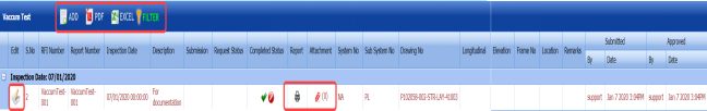
Figure 6.9: Vacuum Test page
6.9.1 Add a Vacuum Test Report
If you want to add a vacuum test report,
- Click
 (ADD button) in the Vacuum Test Report page. See Fig 6.9.
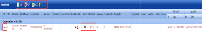
A new window opens to add a vacuum test report.

 Note: The fields notified with a symbol (*) are mandatory. You must enter the relevant details in that fields before saving.
 Tip: A report number for a new vacuum test report will be updated automatically in the Report Number box.
 -
In the Description box, enter the description for the vacuum test.
-
In the Sub-System box, select the sub-system from a drop-down list.
-
In the Inspection Date box, select the inspection date.
-
In the Frame No box, enter the frame number.
-
In the Elevation box, enter the elevation detail.
-
In the Longitudinal box, enter the longitudinal detail.
-
In the Location box, enter the location where the vacuum test is performed.
-
In the Drawing No box, select the drawing number from a drop-down list.
-
In the Sub Contractor box, select the sub-contractor from a drop-down list.
-
In the Remarks box, enter your remarks if any.
-
Click Save.


The vacuum test report is successfully added.
6.9.2 Submit and Approve a Vacuum Test Report
Once you have added the vacuum test report, the Submission column in the Vacuum Test page is appeared with  (Submit and Reject icons).
- If you want to submit the vacuum test report, click
 (Submit icon) in the Submission column. Otherwise click
  (Reject icon) to reject the request.
Once you have submitted the vacuum test report, the Request Status column in the Vacuum Test page is appeared with
 (Accept and Reject icons).
 - If you want to approve the vacuum test report, click
 (Submit icon) in the Request Status Otherwise click
  (Reject icon) to reject the request.


6.9.3 Print a Vacuum Test Report
If you want to print a vacuum test report, click  (print icon) provided in the Report column of the Vacuum Test Report page. See Fig 6.9.
6.9.4 Attach a File into a Vacuum Test Report
If you want to attach any file with any vacuum test report listed in the Vacuum Test page, follow the procedures given in the topic “Attach a file into a client master drawing” in the Client Master Drawing section.
6.9.5 Edit Any Vacuum Test Report
If you want to edit any existing vacuum test report in the Vacuum Test page, do the following,
- Click
 (Edit icon) in the Edit column for the respective vacuum test report. See Fig 6.9.
A new window opens to edit the vacuum test report.
-
Click any box where you want to edit the details, and then edit the details in the respective box.
-
Click Save.

6.9.6 Export Vacuum Test Report List
You can export a list of vacuum test reports added in the Vacuum Test page in the pdf and excel formats. To know how to export, see the topic, “Export Areas list” in the Area option.
6.9.7 Filter Any Vacuum Test Report
If you want to filter any vacuum test report from the list of in the Vacuum Test page, you can use the  (FILTER button). To know how to filter, see the topic, ”Filter Any Area”.
6.10 Back-Gouging
Back-gouging is a removing process performed to remove weld metal and base metal from the weld root side by grinding, gas cutting or by using gouging electrode.
The Back-Gouging tab in the Structural menu helps you to add a back-gouging report once the back-gouging process has completed. If you want to add a back-gouging report, do the following,
- Click the Back-Gouging Tab.
The Back-Gouging page opens.
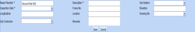
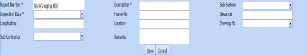
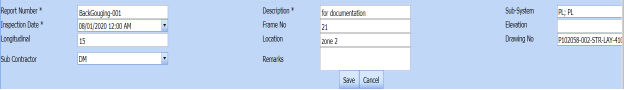
Figure 6.10: Back-Gouging page

6.10.1 Add a Back-Gouging Report
If you want to add a back-gouging report,
- Click
 (ADD button) in the Back-Gouging page. See Fig 6.10.
A new window opens to add a back-gouging report.

 Note: The fields notified with a symbol (*) are mandatory. You must enter the relevant details in that fields before saving.
 Tip: A report number for a new back-gouging report will be updated automatically in the Report Number box.
 -
In the Description box, enter the description for the back-gouging.
-
In the Sub-System box, select the sub-system from a drop-down list.
-
In the Inspection Date box, select the inspection date.
-
In the Frame No box, enter the frame number.
-
In the Elevation box, enter the elevation detail.
-
In the Longitudinal box, enter the longitudinal detail.
-
In the Location box, enter the location where the back-gouging is performed.
-
In the Drawing No box, select the drawing number from a drop-down list.
-
In the Sub Contractor box, select the sub-contractor from a drop-down list.
-
In the Remarks box, enter your remarks if any.
-
Click Save.


The back-gouging report is successfully added.
6.10.2 Add Back-Gouging Report Photos
- Click
 (Edit icon) in the Edit Report column of the Back-Gouging page. See Fig 6.10.
The Report Photos box opens.

-
Click
 (ADD button) in the Report Parameters box.
-
Click
 (Browse button) to browse a photo stored in your computer.
 -
Click Upload.

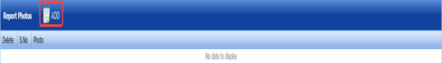


The selected photo will be updated.
6.10.3 Submit and Approve a Back-Gouging Report
Once you have added the back-gouging report, the Submission column in the Back-Gouging page is appeared with  (Submit and Reject icons).
- If you want to submit the back-gouging report, click
 (Submit icon) in the Submission column. Otherwise click
 (Reject icon) to reject the request.
Once you have submitted the back-gouging report, the Request Status column in the Back-Gouging page is appeared with (Accept and Reject icons).
- If you want to approve the back-gouging report, click
 (Submit icon) in the Request Status Otherwise click
  (Reject icon) to reject the request.


6.10.4 Print a Back-Gouging Report
If you want to print a back-gouging report, click (print icon) provided in the Report column of the Back-Gouging page. See Fig 6.10.
6.10.5 View the Back-Gouging Signature Details
If you want to view the signature details of the persons who has completed the back-gouging, click  (Sign icon) provided in the Sign Details column of the Back-Gouging page. See Fig 6.10.
6.10.6 Attach a File into a Back-Gouging Report
If you want to attach any file with any back-gouging report listed in the Back-Gouging page, follow the procedures given in the topic “Attach a file into a client master drawing” in the Client Master Drawing section.
6.10.7 Edit Any Back-Gouging Report
If you want to edit any existing back-gouging report in the Back-Gouging page, do the following,
- Click
 (Edit icon) in the Edit column for the respective back-gouging report. See Fig 6.10.
A new window opens to edit the back-gouging report.
- Click any box where you want to edit the details, and then edit the details in the respective box.
-
Click Save.


6.10.8 Export Back-Gouging Report List
You can export a list of back-gouging reports added in the Back-Gouging page in the pdf and excel formats. To know how to export, see the topic, “Export Areas list” in the Area option.
6.10.9 Filter Any Back-Gouging Report
If you want to filter any back-gouging report from the list of in the Back-Gouging page, you can use the (FILTER button). To know how to filter, see the topic, ”Filter Any Area”.
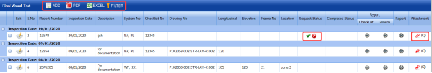
6.11 Final Visual
Visual testing is one of methods of NDT of optical type. Final visual testing is usually performed with the naked eye or with magnifying glasses (magnifiers) with magnification up to 7x.
The Final Visual tab in the Structural menu helps you to add a final visual test report after completing the final visual test. If you want to add a final visual test report, do the following,
- Click the Final Visual Tab.
The Final Visual Test page opens.

Figure 6.11: Final Visual Test page
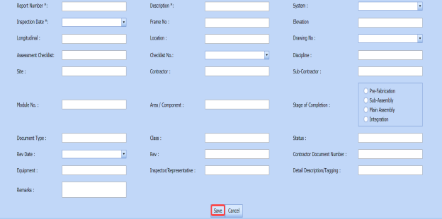
6.11.1 Add a Final Visual Test Report
If you want to add a final visual test report,
- Click
 (ADD button) in the Final Visual Test page. See Fig 6.11.
A new window opens to add a final visual test report.
 Note: The fields notified with a symbol (*) are mandatory. You must enter the relevant details in that fields before saving.
 -
In the Report Number box, enter the report number for the final visual test.
-
In the Description box, enter the description for the final visual test.
-
In the System box, select the system from a drop-down list.
-
In the Inspection Date box, select the inspection date.
-
In the Frame No box, enter the frame number.
-
In the Elevation box, enter the elevation detail.
-
In the Longitudinal box, enter the longitudinal detail.
-
In the Location box, enter the location where the final visual test is performed.
-
In the Drawing No box, select the drawing number from a drop-down list.
-
In the Assessment Checklist box, enter the assessment checklist detail.
-
In the Checklist No box, select the check list number from a drop-down list.
-
In the Discipline box, enter the discipline detail.
-
In the Site box, enter the site detail.
-
In the Contractor box, enter the name of a contractor.
-
In the Sub Contractor box, select the sub-contractor from a drop-down list.
-
In the Module No box, enter the module number.
-
In the Area/ Component box, enter the area/ component detail.
-
In the Stage of Completion box, select the stage of completion of visual test from the given options.
-
In the Document Type box, enter the type of document.
-
In the Class box, enter the class detail.
-
In the Status box, enter the status of the visual test.
-
In the Rev. Date box, enter the revision date of the visual test.
-
In the Contractor Document Number box, enter the document number of the contractor.
-
In the Equipment box, enter the equipment name.
-
In the Inspector/ Representative box, enter the name of inspector/ representative.
-
In the Detail Description/Tagging box, enter the detail description.
-
In the Remarks box, enter your remarks if any.
-
Click Save.
The final visual test report is successfully added.


6.11.2 View Checklist Details
If you want to view the check list details, do the following,
- Click
 (Add icon) in the Edit column for the respective final visual test report in the Final Visual Test See Fig 6.11.
The Check List Details window opens.

The Check List Details window shows a list of added check lists using the Check List tab. This window also shows the results of check list whether accepted or not.

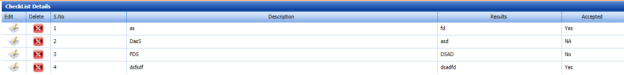
6.11.3 Submit and Approve a Final Visual Test Report
Once you have added the visual test report, the Request Status column in the Final Visual Test page is appeared with (Submit and Reject icons).
- If you want to submit the visual test report, click
 (Submit icon) in the Request Status column. Otherwise click
 (Reject icon) to reject the request.
Once you have submitted the visual test report, the Completed Status column in the Final Visual Test page is appeared with
 (Accept and Reject icons).
 - If you want to approve the visual test report, click
 (Submit icon) in the Completed Status Otherwise click
  (Reject icon) to reject the request.


6.11.4 Print a Final Visual Checklist Report
If you want to print a final visual checklist report, click (print icon) provided in the Checklist Report column of the Final Visual Test page. See Fig 6.11.
6.11.5 Print a General Visual Checklist Report
If you want to print a general visual checklist report, click  (print icon) provided in the General Report column of the Final Visual Test page. See Fig 6.11.
6.11.6 Print a Final Visual Test Report
If you want to print a final visual test report, click (print icon) provided in the Report column of the Final Visual Test page. See Fig 6.11.
6.11.7 Attach a File into a Final Visual Test Report
If you want to attach any file with any final visual test report listed in the Final Visual Test page, follow the procedures given in the topic “Attach a file into a client master drawing” in the Client Master Drawing section.
6.11.8 Edit Any Final Visual Test Report
If you want to edit any existing final visual test report in the Final Visual Test page, do the following,
- Click
 (Edit icon) in the Edit column for the respective final visual test report. See Fig 6.11.
A new window opens to edit the final visual test report.
- Click any box where you want to edit the details, and then edit the details in the respective box.
-
Click Save.

6.11.9 Export Final Visual Test Report List
You can export a list of final visual test reports added in the Final Visual Test page in the pdf and excel formats. To know how to export, see the topic, “Export Areas list” in the Area option.
6.11.10 Filter Any Final Visual Test Report
If you want to filter any visual test report from the list of in the Final Visual Test page, you can use the (FILTER button). To know how to filter, see the topic, ”Filter Any Area”.
6.12 Machining Report
The Machining Report tab in the Structural menu used to add a machining report once the machining process has completed. If you want to add a machining report, do the following,
- Click the Machining Report Tab.
The Machining page opens.

Figure 6.12: Machining page
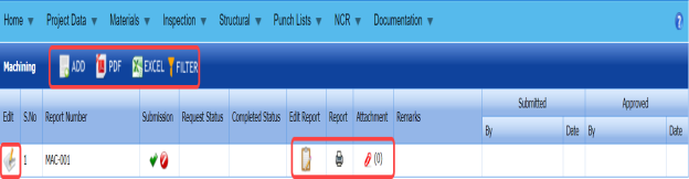
6.12.1 Add a Machining Report
If you want to add a machining report,
- Click
 (ADD button) in the Machining page. See Fig 6.12.
A new window opens to add a machining report.
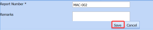
 Tip: A report number for a new machining report will be updated automatically in the Report Number box.
 -
In the Remarks box, enter your remarks if any.
-
Click Save.


The machining report is successfully added.
6.12.2 Add Machining Report Details
- Click
 (Edit icon) in the Edit Report column of the Machining page. See Fig 6.12.
The Machining Report Details window opens.

-
Click
 (ADD button) in the Machining Report Details window.
A new window opens in the Drawing No column.

- In the Drawing No column, select the drawing number from a drop-down list.
-
In the Piece Mark No column, click and select the piece mark number from a drop-down list.
-
In the Description column, click and enter the description.
-
In the Material Grade column, click and enter the material grade.
- In the Hole Before Line Boring (mm)column, enter the size of a hole made before line boring.
-
In the Hole After Line Boring (mm) column, enter the size of a hole made after line boring.
-
In the Deviation column, enter the deviation between holes.
-
In the Inspection Date column, select the inspection date.
-
In the Remarks column, enter your remarks if any.
-
Click Save.


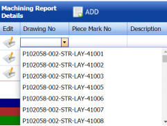
The added machining report details will be updated.
6.12.3 Submit and Approve a Machining Report
Once you have added the machining report details, the Submission column in the Machining page is appeared with (Submit and Reject icons).
- If you want to submit the machining report, click
 (Submit icon) in the Submission Otherwise click
  (Reject icon) to reject the request.
Once you have submitted the machining report, the Request Status column in the Machining page is appeared with
 (Accept and Reject icons).
 -
If you want to approve the machining report, click
 (Submit icon) in the Request Status column. Otherwise click
  (Reject icon) to reject the request.
 -
If you have completed the machining report, click
 (Completed icon) in the Completed Status column. If incomplete, click
  (Incomplete icon).


6.12.4 Print a Machining Report
If you want to print a machining report, click (print icon) provided in the Report column of the Machining page. See Fig 6.12.
6.12.5 Attach a File into a Machining Report
If you want to attach any file with any machining report listed in the Machining page, follow the procedures given in the topic “Attach a file into a client master drawing” in the Client Master Drawing section.
6.12.6 Edit Any Machining Report
If you want to edit any existing machining report in the Machining page, do the following,
- Click
 (Edit icon) in the Edit column for the respective machining report. See Fig 6.12.
A new window opens to edit the machining report.
-
Click any box where you want to edit the details, and then edit the details in the respective box.
-
Click Save.

6.12.7 Export Machining Report List
You can export a list of machining reports added in the Machining page in the pdf and excel formats. To know how to export, see the topic, “Export Areas list” in the Area option.
6.12.8 Filter any machining report
If you want to filter any machining report from the list in the Machining page, you can use the (FILTER button). To know how to filter, see the topic, ”Filter Any Area”.
6.13 Load Test Report
The Load Test Report tab in the Structural menu used to add a load test report once the load test has completed. If you want to add a load test report, do the following,
- Click the Load Test Report Tab.
The Load Test Report page opens.
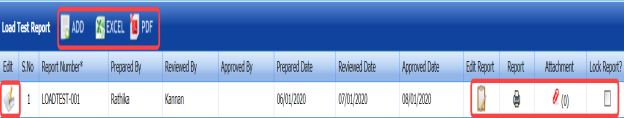
Figure 6.13: Load Test Report page

6.13.1 Add a Load Test Report
If you want to add a load test report,
- Click
 (ADD button) in the Load Test Report page. See Fig 6.13.
A new window opens to add a load test report.
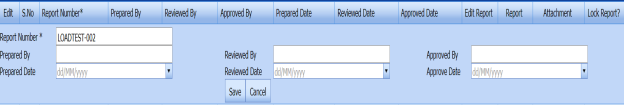
 Tip: A report number for a new load test report will be updated automatically in the Report Number box.
 -
In the Prepared By box, enter the name a person who has prepared the load test report.
-
In the Prepared Date box, enter the prepared date of the load test report.
-
In the Reviewed By box, enter the name a person who has reviewed the load test report.
-
In the Reviewed Date box, enter the reviewed date of the load test report.
-
In the Approved By box, enter the name a person who has approved the load test report.
-
In the Approved Date box, enter the approved date of the load test report.
-
Click Save.


The load test report is successfully added. Once you have added the load test report, you must add the details for the added report.
6.13.2 Add Load Test Report Details
- Click
 (Edit icon) in the Edit Report column of the Load Test Report See Fig 6.14.
The Load Test Parameters, Equipment Details, and Report Photos windows open in the Load Test Report page.
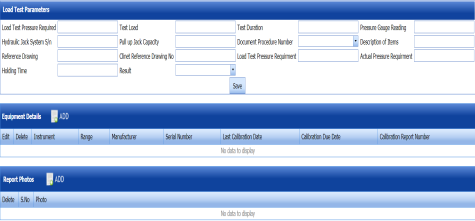
- If you want to add the load test parameters in the Load Test Parameters window, do the following,
-
-
-
In the Load Test Pressure Required box, enter the required range of load test pressure.
-
In the Test Load box, enter the test load detail.
-
In the Test Duration box, enter the load test time duration.
-
In the Pressure Gauge Reading box, enter the pressure gauge reading value.
-
In the Hydraulic Jack System S/N box, enter the hydraulic jack system detail.
-
In the Pull up Jack Capacity box, enter the value of pull up jack capacity.
-
In the Document Procedure No box, select the document procedure number from a drop-down list.
-
In the Description of Items box, enter the item description.
-
In the Reference Drawing box, enter the reference drawing detail.
-
In the Client Reference Drawing No box, enter the client reference drawing number.
-
In the Load Test Pressure Requirement box, enter the requirement for load test pressure.
-
In the Actual Pressure Requirement box, enter the requirement for actual pressure.
-
In the Holding Time box, enter the holding time duration.
-
In the Result box, select the result from a drop-down list.
-
Click Save.
-
-
-
- If you want to add the equipment details in the Equipment Details window, do the following,
-
-
- Click
 (ADD button) in the Equipment Details window.
A new window opens to add the equipment details.
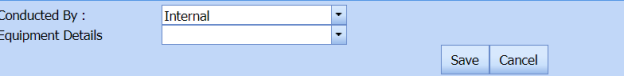
-
In the Conducted By box, select Internal if the load test is conducted internally or select External if the load test is conducted externally.
-
In the Equipment Details box, select the equipment from a drop-down list.
-
Click Save.
- Click
-
-
- If you want to add the report photos in the Report Photos window, do the following,
-
-
-
Click
 (ADD button) in the Report Photos window.
-
Click
 (Browse button) to browse a photo stored in your computer.
 -
Click Upload.
The selected photo will be updated.
-
-
-


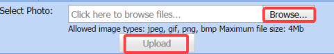

6.13.3 Print a Load Test Report
If you want to print a load test report, click  (print icon) provided in the Report column of the Load Test Report page. See Fig 6.13.
 Tip: If you want to lock any load test report, click the check box provided in the Lock Report? column of the Load Test Report page. See Fig 6.13.
6.13.4 Attach a File into a Load Test Report
If you want to attach any file with any load test report listed in the Load Test Report page, follow the procedures given in the topic “Attach a file into a client master drawing” in the Client Master Drawing section.
6.13.5 Edit Any Load Test Report
If you want to edit any existing load test report in the Load Test Report page, do the following,
- Click
 (Edit icon) in the Edit column for the respective load test report. See Fig 6.13.
A new window opens to edit the load test report.
- Click any box where you want to edit the details, and then edit the details in the respective box.
- Click Save.

6.13.6 Export Load Test Report List
You can export a list of load test reports added in the Load Test Report page in the pdf and excel formats. To know how to export, see the topic, “Export Areas list” in the Area option.
6.14 Survey Booking
Survey Booking is an enhanced survey booking process, which helps the surveyors to manage their survey requirements more efficiently with respect to time and scope.
The Survey Booking tab in the Structural menu helps in adding a survey booking once the survey booking process has completed.
If you want to add a survey booking, do the following,
- Click the Survey Booking Tab.
The Survey Booking page opens.
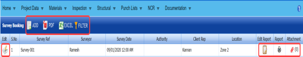
Figure 6.14: Survey Booking page

6.14.1 Add a Survey Booking
If you want to add a survey booking,
- Click
 (ADD button) in the Survey Booking page. See Fig 6.15.
A new window opens to add a survey booking.
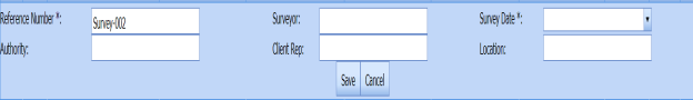
-
In the Surveyor box, enter the name of a surveyor.
- In the Survey Date box, select the survey date from a drop-down list.
-
In the Authority box, enter the name of authority person.
-
In the Client Rep box, enter the name of the client representative.
-
In the Location box, enter the location where the survey to be performed.
-
Click Save.


The survey booking is successfully added.
6.14.2 Add Survey Booking Details
- Click
 (Edit icon) in the Edit Report column of the Survey Booking See Fig 6.14.
The Survey Booking Details window opens.

-
Click
 (ADD button) in the Survey Booking Details window.
A new window opens to add the survey booking details.
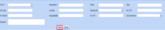
- In the Time box, select the survey time.
-
In the Description box, enter the description for the survey booking.
- In the Trade box, enter the trade detail.
- In the Type box, enter the type of survey.
- In the QC Code box, enter the QC code.
- In the Location box, enter the location where the survey is to be performed.
- In the Drawing No box, select the drawing number from a drop-down list.
- In the For CTR box, enter the CTR detail.
- In the For RG/ CA box, enter the RG/ CA detail.
- In the Requested By box, enter the name of a person who has requested for the survey booking.
- In the For CPY box, enter the CPY detail.
-
In the Sub Contractor box, select the sub-contractor name from a drop-down list.
-
In the Remarks column, enter your remarks if any.
-
Click Save.

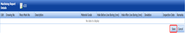

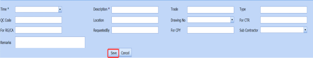
The survey booking details will be updated.
6.14.3 Print a Survey Booking Report
If you want to print a survey booking report, click  (print icon) provided in the Report column of the Survey Booking page. See Fig 6.14.
6.14.4 Attach a File into a Survey Booking
If you want to attach any file with any survey booking listed in the Survey Booking page, follow the procedures given in the topic “Attach a file into a client master drawing” in the Client Master Drawing section.
6.14.5 Edit Any Survey Booking
If you want to edit any existing survey booking in the Survey Booking page, do the following,
- Click
 (Edit icon) in the Edit column for the respective survey booking. See Fig 6.14.
A new window opens to edit the survey booking.
- Click any box where you want to edit the details, and then edit the details in the respective box.
-
Click Save.

6.14.6 Export Survey Booking List
You can export a list of survey booking added in the Survey Booking page in the pdf and excel formats. To know how to export, see the topic, “Export Areas list” in the Area option.
6.14.7 Filter Any Survey Booking
If you want to filter any survey booking from the list in the Survey Booking page, you can use the  (FILTER button). To know how to filter, see the topic, ”Filter Any Area”.
6.15 Dimensional Control Report
Dimensional control used to determine part-to-part variation and clearance between two parts of material. By applying Dimensional Control, accurate three-dimensional information can be determined and mapped at various stages throughout the Structural project.
The Dimensional Control Report tab in the Structural menu used to add a dimensional control report once the dimensional control has completed. If you want to add a dimensional control report, do the following,
- Click the Dimensional Control Report Tab.
The Dimensional Control Report page opens.
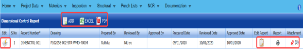
Figure 6.15: Dimensional Control Report page

6.15.1 Add a dimensional control report
If you want to add a dimensional control report,
- Click
 (ADD button) in the Dimensional Control Report See Fig 6.15.
A new window opens to add a dimensional control report.

 Note: The fields notified with a symbol (*) are mandatory. You must enter the relevant details in that fields before saving.
 Tip: A report number for a new dimensional control report will be updated automatically in the Report Number box.
 -
In the Drawing box, select the drawing from a drop-down list.
-
In the Prepared By box, enter the name a person who has prepared the dimensional control report.
-
In the Prepared Date box, enter the prepared date of the dimensional control report.
-
In the Reviewed By box, enter the name a person who has reviewed the dimensional control report.
-
In the Reviewed Date box, enter the reviewed date of the dimensional control report.
-
In the Approved By box, enter the name a person who has approved the dimensional control report.
-
In the Approved Date box, enter the approved date of the dimensional control report.
-
Click Save.

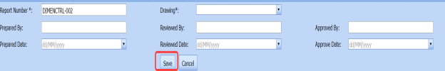


The dimensional control report is successfully added. Once you have added the dimensional control report, you must add the details for the added dimensional control report.
6.15.2 Add Dimensional Control Report Details
- Click
 (Edit icon) in the Edit Report column of the Dimensional Control Report See Fig 6.15.
The Dimensional Control Parameters, Dimensional Control Details, and Report Photos windows open in the Dimensional Control Report page.
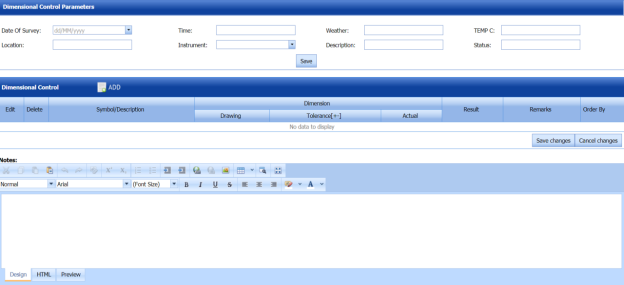
 Tip: If you want to add any notes for dimensional control report, you can add in the Notes window provided in the Dimensional Control Report page.
 - If you want to add the dimensional control parameters in the Dimensional Control Parameters window, do the following,
-
-
-
In the Date of Survey box, enter the survey date.
-
In the Time box, enter the survey time.
-
In the Weather box, enter the weather details.
-
In the Temp C box, enter the temperature control value.
- In the Location box, enter the location where the dimensional control is to be performed
-
In the Instrument box, select the instrument from a drop-down list.
-
In the Description box, enter the description for dimensional control.
-
In the Status box, enter the status for dimensional control.
-
Click Save.
-
-
-
-
If you want to add the dimensional control details in the Dimensional Control Details window, do the following,
-
-
- Click
 (ADD button) in the Dimensional Control Details window.
Boxes opens in the respective columns to add the dimensional control details.
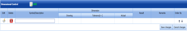
 Tip: You can add multiple dimensional control result details by using the ADD button. If you want to order the added details, use the up and down symbols in the Order By column.
 - In the Symbol/ Description column, enter the symbol or description for the dimensional control.
-
In the Drawing column, enter the drawing detail.
-
In the Tolerance column, enter the tolerance value.
-
In the Actual column, enter the actual value.
-
In the Result column, enter the result for the dimensional control.
-
In the Remarks column, enter your remarks if any.
-
Click Save Changes.
- Click
-
-
- If you want to add the report photos in the Report Photos window, do the following,
-
-
-
Click
 (ADD button) in the Report Photos window.
-
Click
 (Browse button) to browse a photo stored in your computer.
 -
Click Upload.
The selected photo will be updated.
-
-
-


6.15.3 Print a Dimensional Control Report
If you want to print a dimensional control report, click  (print icon) provided in the Report column of the Dimensional Control Report page. See Fig 6.15.
6.15.4 Attach a File into a Dimensional Control Report
If you want to attach any file with any dimensional control report listed in the Dimensional Control Report page, follow the procedures given in the topic “Attach a file into a client master drawing” in the Client Master Drawing section.
6.15.5 Edit Any Dimensional Control Report
If you want to edit any existing dimensional control report in the Dimensional Control Report page, do the following,
- Click
 (Edit icon) in the Edit column for the respective dimensional control report. See Fig 6.15.
A new window opens to edit the dimensional control report.
- Click any box where you want to edit the details, and then edit the details in the respective box.
-
Click Save.

6.15.6 Export Dimensional Control Report List
You can export a list of dimensional control reports added in the Dimensional Control Report page in the pdf and excel formats. To know how to export, see the topic, “Export Areas list” in the Area option.
6.16 Trail Fit Report
Trail Fit report prepared to send the trail fit-up photos once the trail fit-up has completed. The Trail Fit Report tab in the Structural menu used to add a trail fit report. If you want to add a trail fit report, do the following,
- Click Trail Fit Report in the Structural menu. The Trail Fit Report page opens.

Figure 6.16: Trail Fit Report page
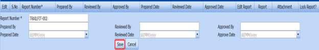
6.16.1 Add a Trail Fit Report
If you want to add a trail fit report,
- Click
 (ADD button) in the Trail Fit Report page. See Fig 6.16.
A new window opens to add a trail fit report.

 Tip: A report number for a new trail fit report will be updated automatically in the Report Number box.
 - In the Prepared By box, enter the name a person who has prepared the trail fit report.
-
In the Prepared Date box, enter the prepared date of the trail fit report.
-
In the Reviewed By box, enter the name a person who has reviewed the trail fit report.
-
In the Reviewed Date box, enter the reviewed date of the trail fit report.
-
In the Approved By box, enter the name a person who has approved the trail fit report.
-
In the Approved Date box, enter the approved date of the trail fit report.
-
Click Save.

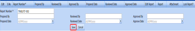

The trail fit report is successfully added. Once you have added the trail fit report, you must add the trail fit details for the added trail fit report.
6.16.2 Add Trail Fit Report Details
- Click
 (Edit icon) in the Edit Report column of the Trail Fit Report See Fig 6.16.
The Report Photos window opens in the Trail Fit Report page.

 Tip: If you want to add any remarks for trail fit report, you can add in the Remarks window provided in the Trail Fit Report page.
 -
If you want to add the report photos in the Report Photos window, do the following,
-
-
Click
 (ADD button) in the Report Photos window.
-
Click
 (Browse button) to browse a photo stored in your computer.
 -
Click Upload.
The selected photo will be updated.
-
-

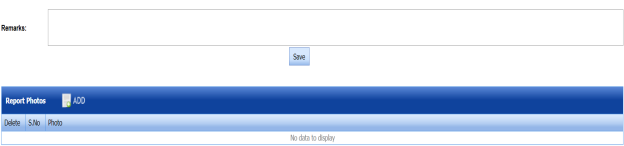


6.16.3 Print a Trail Fit Report
If you want to print a trail fit report, click  (print icon) provided in the Report column of the Trail Fit Report page. See Fig 6.16.
 Tip: If you want to lock any trail fit report, click the check box provided in the Lock Report? column of the Trail Fit Report page. See Fig 6.16.
6.16.4 Attach a File into a Trail Fit Report
If you want to attach any file with any trail fit report listed in the Trail Fit Report page, follow the procedures given in the topic “Attach a file into a client master drawing” in the Client Master Drawing section.
6.16.5 Edit Any Trail Fit Report
If you want to edit any existing trail fit report in the Trial Fit Report page, do the following,
- Click
 (Edit icon) in the Edit column for the respective trail fit report. See Fig 3.16.
A new window opens to edit the trail fit report.
- Click any box where you want to edit the details, and then edit the details in the respective box.
-
Click Save.

6.16.6 Export Trail Fit Report List
You can export a list of trail fit reports added in the Trail Fit Report page in the pdf and excel formats. To know how to export, see the topic, “Export Areas list” in the Area option.
6.17 Heat Straightening Report
Heat straightening is a repair procedure in which controlled heat is applied in specific patterns to the plastically deformed regions of damaged material in repetitive heating and cooling cycles to gradually straighten the material.
The Heat Straightening Report tab in the Structural menu used to add a heat straightening report once the heat straightening process has completed. If you want to add a heat straightening report, do the following,
- Click the Heat Straightening Report Tab.
The Heat Straightening Report page opens.
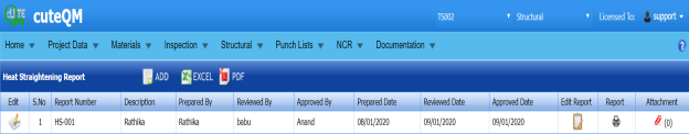
Figure 6.17: Heat Straightening Report page

6.17.1 Add a Heat Straightening Report
If you want to add a heat straightening report,
- Click
 (ADD button) in the Heat Straightening Report See Fig 6.17.
A new window opens to add a heat straightening report.

 Tip: A report number for a new heat straightening report will be updated automatically in the Report Number box.
 - In the Description box, enter the description for the heat straightening report.
-
In the Description box, enter the description for the heat straightening report.
-
In the Prepared Date box, enter the prepared date of the heat straightening report.
-
In the Prepared Date box, enter the prepared date of the heat straightening report.
-
In the Reviewed Date box, enter the reviewed date of the heat straightening report.
-
In the Approved By box, enter the name a person who has approved the heat straightening report.
- In the Approved Date box, enter the approved date of the heat straightening
-
Click Save.

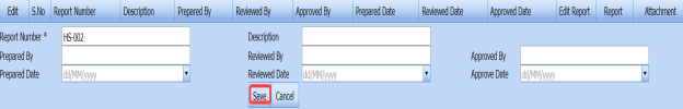

The heat straightening report is successfully added. Once you have added the heat straightening report, you must add the heat straightening details for the added report.
6.17.2 Add Heat Straightening Details
- Click
 (Edit icon) in the Edit Report column of the Heat Straightening Report page. See Fig 6.17.
The Report Parameters and Report Photos windows open in the Heat Straightening Report page.
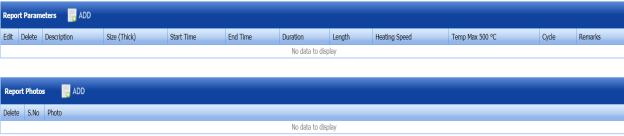
- If you want to add the report parameters in the Report Parameters window, do the following,
-
-
Click
 (ADD button) in the Report Parameters window.
 -
In the Description box, enter the description for heat straightening.
-
In the Size box, enter the thickness of the material.
-
In the Start Time box, enter the start time of heat straightening.
-
In the End Time box, enter the end time of heat straightening.
-
In the Temperature box, enter the temperature range for heat straightening.
-
In the Length box, enter the length of material to do heat straightening.
-
In the Heating Speed box, enter the heating speed of heat straightening.
-
In the Cycle box, enter the detail of heat straightening cycle.
-
In the Remarks box, enter your remarks if any.
-
Click Save.
-
-
-
If you want to add the report photos in the Report Photos window, do the following,
-
-
Click
 (ADD button) in the Report Photos window.
-
Click
 (Browse button) to browse a photo stored in your computer.
 -
Click Upload.
The selected photo will be updated.
-
-


6.17.3 Print a Heat Straightening Report
If you want to print a heat straightening report, click (print icon) provided in the Report column of the Heat Straightening Report page. See Fig 6.17.
6.17.4 Attach a File into a Heat Straightening Report
If you want to attach any file with any heat straightening report listed in the Heat Straightening Report page, follow the procedures given in the topic “Attach a file into a client master drawing” in the Client Master Drawing section.
6.17.5 Edit Any Heat Straightening Report
If you want to edit any existing heat straightening report in the Heat Straightening Report page, do the following,
- Click
 (Edit icon) in the Edit column for the respective heat straightening report. See Fig 6.17.
A new window opens to edit the heat straightening report.
-
Click any box where you want to edit the details, and then edit the details in the respective box.
-
Click Save.

6.17.6 Export Heat Straightening Report List
You can export a list of heat straightening reports added in the Heat Straightening Report page in the pdf and excel formats. To know how to export, see the topic, “Export Areas list” in the Area option.
6.18 Inspection Release Note
Inspection Release Note is a written announcement which is issued by QC contractor to denote the successful completion of the inspection.
The Inspection Release Note tab in the Structural menu used to add an inspection release note after completion of the inspection. If you want to add an inspection release note, do the following,
- Click the Inspection Release Note Tab.
The Release Form page opens.
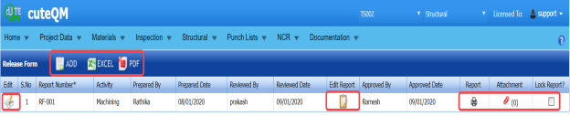
Figure 6.18: Release Form page

6.18.1 Add an Inspection Release Note
If you want to add an inspection release note,
- Click
 (ADD button) in the Release Form page. See Fig 6.18.
A new window opens to add an inspection release note.

 Tip: A report number for a new inspection release note will be updated automatically in the Report Number box.
 -
In the Activity box, select the activity from a drop-down list.
-
In the Prepared By box, enter the name a person who has prepared the inspection release note.
-
In the Prepared Date box, enter the prepared date of the inspection release note.
-
In the Reviewed By box, enter the name a person who has reviewed the inspection release note.
-
In the Reviewed Date box, enter the reviewed date of the inspection release note.
-
In the Approved By box, enter the name a person who has approved the inspection release note.
- In the Approved Date box, enter the approved date of the inspection release note.
-
Click Save.

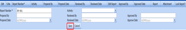

The inspection release note is successfully added. Once you have added the inspection release note, you must add the details for the added note.
6.18.2 Add Inspection Release Note Details
- Click
 (Edit icon) in the Edit Report column of the Release Form See Fig 6.18.
The Release Form Parameters, Details, and Report Photos windows open in the Release Form page.

- If you want to add the release form parameters in the Release Form Parameters window, do the following,
-
-
In the Test Package No box, enter the test package number.
-
In the Tag ID box, enter the tag ID number.
-
In the Activity box, enter the activity detail.
- In the Comments box, enter any comments relevant to the inspection release note.
-
Click Save.
-
-
- If you want to add the release note details in the Details window, do the following,
-
-
Click
 (ADD button) in the Details window.
A new window opens to add the release note details.
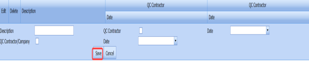
-
In the Description box, enter the description for the inspection release note.
-
If the company’s QC contractor issues the inspection release note, select the check box provided with the QC Contractor/ Company and select the date in the respective Date box.
-
If the company’s QC contractor issues the inspection release note, select the check box provided with the QC Contractor/ Company and select the date in the respective Date box.
-
Click Save.
-
-
- If you want to add the report photos in the Report Photos window, do the following,
-
-
Click
 (ADD button) in the Report Photos window.
- Click
 (Browse button) to browse a photo stored in your computer.
 -
Click Upload.
-
-

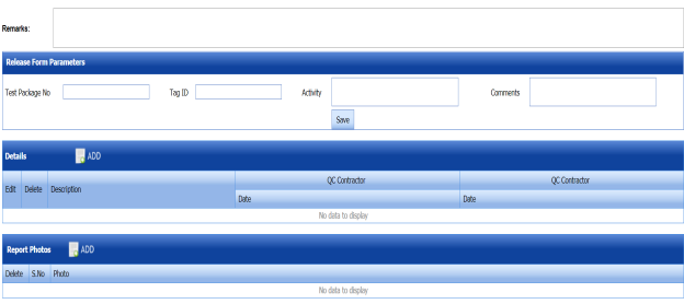


The selected photo will be updated.
6.18.3 Print an Inspection Release Form Report
If you want to print an inspection release form report, click  (print icon) provided in the Report column of the Release Form page. See Fig 6.18.
 Tip: If you want to lock any inspection release note, click the check box provided in the Lock Report? column of the Release Form page. See Fig 6.18.
6.18.4 Attach a File into an Inspection Release Note
If you want to attach any file with any inspection release note listed in the Release Form page, follow the procedures given in the topic “Attach a file into a client master drawing” in the Client Master Drawing section.
6.18.5 Edit Any Inspection Release Note
If you want to edit any existing inspection release note in the Release Form page, do the following,
- Click
 (Edit icon) in the Edit column for the respective inspection release note. See Fig 6.18.
A new window opens to edit the inspection release note.
-
Click any box where you want to edit the details, and then edit the details in the respective box.
-
Click Save.

6.18.6 Export Inspection Release Note List
You can export a list of inspection release notes added in the Release Form page in the pdf and excel formats. To know how to export, see the topic, “Export Areas list” in the Area option.
6.19 Shell Plate Rolling Report
Shell Plate Rolling is a process of rolling different kinds of metal plates into a round or conical shape by using a plate rolling machine in the Structural project.
The Shell Plate Rolling Report tab in the Structural menu used to add a shell plate rolling report once the shell plate rolling process has completed. If you want to add a shell plate rolling report, do the following,
- Click the Shell Plate Rolling Report Tab.
The Shell Plate Rolling Report page opens.

Figure 6.19: Shell Plate Rolling Report page.
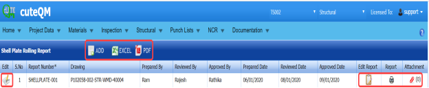
6.19.1 Add a Shell Plate Rolling Report
If you want to add a shell plate rolling report,
- Click
 (ADD button) in the Shell Plate Rolling Report See Fig 6.19.
A new window opens to add a shell plate rolling report.

 Note: The fields notified with a symbol (*) are mandatory. You must enter the relevant details in that fields before saving.
 Tip: A report number for a new shell plate rolling report will be updated automatically in the Report Number box.
 -
In the Drawing box, select the drawing from a drop-down list.
- In the Prepared By box, enter the name a person who has prepared the shell plate rolling report.
-
In the Prepared Date box, enter the prepared date of the shell plate rolling report.
-
In the Prepared Date box, enter the prepared date of the shell plate rolling report.
-
In the Reviewed By box, enter the name a person who has reviewed the shell plate rolling report.
- In the Reviewed Date box, enter the reviewed date of the shell plate rolling report.
- In the Approved By box, enter the name a person who has approved the shell plate rolling report.
-
In the Approved Date box, enter the approved date of the shell plate rolling report.
-
Click Save.

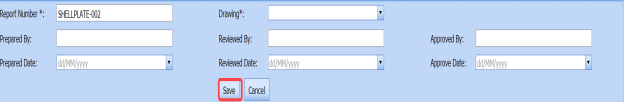


The shell plate rolling report is successfully added. Once you have added the shell plate rolling report, you must add the details for the added report.
6.19.2 Add Shell Plate Rolling Report Details
- Click
 (Edit icon) in the Edit Report column of the Shell Plate Rolling Report page. See Fig 6.19.
The Shell Plate Rolling Details and Report Photos windows open in the Shell Plate Rolling Report page.

 Tip: If you want to add any notes for the shell plate rolling report, you can add in the Notes window provided in the Shell Plate Rolling Report page.
 - If you want to add the shell plate rolling details in the Shell Plate Rolling Details window, do the following,
-
-
- Click
 (ADD button) in the Shell Plate Rolling Details window.
Boxes opens in the respective columns to add the shell plate rolling details.

-
In the PLATE HEAT NO column, enter the heat number of the plate.
-
In the DATE column, select the date when the shell plate rolling process is performed.
-
In the (S) EXTREME CURVATURE column, enter the extreme curvature value for the respective A SIDE and B SIDE of the rolling plate.
-
In the (R) CURVATURE column, enter the radius curvature value of the rolling plate.
-
In the LENGTH column, enter the length of C SIDE and D SIDE of the rolling plate.
-
In the EDGE- PREPARATION column, enter the root and angle values for A, B, C, and D SIDES, respectively.
-
Click Save Changes.
- Click
-
-
-
If you want to add the report photos in the Report Photos window, do the following,
-
-
-
Click
 (ADD button) in the Report Photos window.
- Click (Browse button) to browse a photo stored in your computer.
-
Click Upload.
The selected photo will be updated.
-
-
-

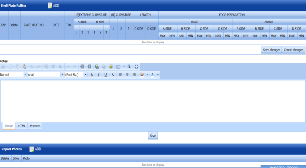


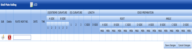


6.19.3 Print a Shell Plate Rolling Report
If you want to print a shell plate rolling report, click (print icon) provided in the Report column of the Shell Plate Rolling Report page. See Fig 6.19.
6.19.4 Attach a File into a Shell Plate Rolling Report
If you want to attach any file with any shell plate rolling report listed in the Shell Plate Rolling Report page, follow the procedures given in the topic “Attach a file into a client master drawing” in the Client Master Drawing section.
6.19.5 Edit Any Shell Plate Rolling Report
If you want to edit any existing shell plate rolling report in the Shell Plate Rolling Report page, do the following,
- Click
 (Edit icon) in the Edit column for the respective shell plate rolling report. See Fig 6.19.
A new window opens to edit the shell plate rolling report.
-
Click any box where you want to edit the details, and then edit the details in the respective box.
-
Click Save.

6.19.6 Export Shell Plate Rolling Report List
You can export a list of shell plate rolling reports added in the Shell Plate Rolling Report page in the pdf and excel formats. To know how to export, see the topic, “Export Areas list” in the Area option.
6.20 Deviation Request Report
Deviation Report used to find out any deviations in the materials utilized in the Structural project. The Deviation Request Report tab in the Structural menu helps you to add a deviation request report.
If you want to add a deviation request report, do the following,
- Click the Deviation Request Report Tab.
The Deviation Request Report page opens.

Figure 6.20: Deviation Request Report page
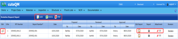
6.20.1 Add a Deviation Request Report
If you want to add a deviation request report,
- Click
 (ADD button) in the Deviation Request Report See Fig 6.20.
A new window opens to add a deviation request report.
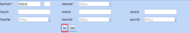
 Note: The fields notified with a symbol (*) are mandatory. You must enter the relevant details in that fields before saving.
 Tip: A report number for a new deviation request report will be updated automatically in the Report Number box.
 - In the Inspection Date box, select the inspection date of the deviation request report.
- In the Prepared By box, enter the name a person who has prepared the deviation request report.
-
In the Prepared Date box, enter the prepared date of the deviation request report.
- In the Reviewed By box, enter the name a person who has reviewed the deviation request report.
-
In the Reviewed Date box, enter the reviewed date of the deviation request report.
-
In the Reviewed Date box, enter the reviewed date of the deviation request report.
-
In the Approved Date box, enter the approved date of the deviation request report.
-
Click Save.


The deviation request report is successfully added. Once you have added the deviation request report, you must add the details for the added deviation request.
 Tip: If you want to add a copy of added deviation request report, click Revision in the Revision column of the Deviation Request Report page.
6.20.2 Add Deviation Request Details
- Click
 (Edit icon) in the Edit Report column of the Deviation Request Report See Fig 6.20.
The Material Clarification, Ref. Documents, Query Description, Attachments, Proposed Solutions, and Technip Response windows open in the Deviation Request Report page.


-
To add the material clarification details, do the following,
-
-
- In the From and To boxes, enter details of deviation occurred up to which material.
- In the Impact box, if the deviation leads to the cost impact then select Cost Impact or if the deviation leads to the schedule impact then select Schedule Impact.
- In the Criticality box, if there is need to correct the deviation in the materials immediately then select Urgent otherwise select Routine based on the deviation criticality.
-
In the Classification box, if the classification of deviation is mandatory then select Mandatory otherwise select Non- Mandatory.
- In the Requirements box, if you need clarification for the deviations occurred then select Clarification otherwise select Change to Project Requirement.
-
Click Save.
-
-
-
To add reference documents of the material deviations,
-
-
- Click
 (ADD button) in the Documents window.
A new window opens in the Technip Document No column to add the reference document number.
- Enter the revision detail for the reference document number in the Revision column.
-
Enter the vendor document number in the Vendor Document No column.
-
Enter the revision detail for the vendor document number in the Revision column.
-
Click Save Changes.
- Click
-
-
-
If you want to add query description, you can add in the Query Description window.
-
To add any attachment for the deviation request report,
-
-
-
Click
 (ADD button) in the Attachments window.
A new window opens in the Document No column to add the number of a document to be attached.
- Enter the revision detail for the document number in the Revision column.
-
Enter the title of the document in the Title column.
-
Click Save Changes.
-
-
-
-
If you want to add the proposed solution details for the material deviation, you can add in the Proposed Solutions window.
-
If you want to add the proposed solution details for the material deviation, you can add in the Proposed Solutions window.


6.20.3 Print a Deviation Request Report
If you want to print a deviation request report, click (print icon) provided in the Report column of the Deviation Request Report page. See Fig 6.20.
6.20.4 Attach a File into a Deviation Request Report
If you want to attach any file with any deviation request report listed in the Deviation Request Report page, follow the procedures given in the topic “Attach a file into a client master drawing” in the Client Master Drawing section.
6.20.5 Edit Any Deviation Request Report
If you want to edit any existing deviation request report in the Deviation Request Report page, do the following,
- Click
 (Edit icon) in the Edit column for the respective deviation request report. See Fig 6.20.
A new window opens to edit the deviation request report.
- Click any box where you want to edit the details, and then edit the details in the respective box.
-
Click Save.

6.20.6 Export Deviation Request Report List
You can export a list of deviation request reports added in the Deviation Request Report page in the pdf and excel formats. To know how to export, see the topic, “Export Areas list” in the Area option.
6.21 Technical Query Report
Technical query usually raised to get clarification on technical fault, which is occurred in the execution of the Structural project. The Technical query can be raised between site operations of the contractor and engineering team of the contractor.
The Technical Query Report tab in the Structural menu used to add a technical query report. If you want to add a technical query report, do the following,
- Click the Technical Query Report Tab.
The Technical Query Report page opens.
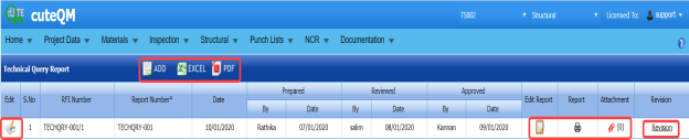
Figure 6.21: Technical Query Report page

6.21.1 Add a Technical Query Report
If you want to add a technical query report,
- Click
 (ADD button) in the Technical Query Report page. See Fig 6.21.
A new window opens to add a technical query report.
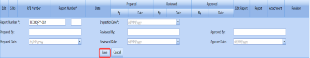
 Note: The fields notified with a symbol (*) are mandatory. You must enter the relevant details in that fields before saving.
 Tip: A report number for a new technical query report will be updated automatically in the Report Number box.
 -
In the Inspection Date box, select the inspection date of the technical query report.
-
In the Prepared By box, enter the name a person who has prepared the technical query report.
- In the Prepared Date box, enter the prepared date of the technical query report.
- In the Reviewed By box, enter the name a person who has reviewed the technical query report.
- In the Reviewed Date box, enter the reviewed date of the technical query report.
-
In the Approved By box, enter the name a person who has approved the technical query report.
- In the Approved Date box, enter the approved date of the deviation request report.
- Click Save.


The technical query report is successfully added. Once you have added the technical query report, you must add the details for the added report.
 Tip: If you want to add a copy of added technical query report, click Revision in the Revision column of the Technical Query Report page.
6.21.2 Add Technical Query Report Details
- Click
 (Edit icon) in the Edit Report column of the Technical Query Report See Fig 6.21.
The Material Clarification, Ref. Documents, Query Description, Attachments, Proposed Solutions, and Technip Response windows open in the Technical Query Report page.

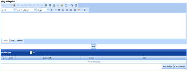

-
To add the material clarification details, do the following,
-
-
-
In the From and To boxes, enter details of technical fault.
- In the Impact box, if the technical fault leads to the cost impact then select Cost Impact or if the technical fault leads to the schedule impact then select Schedule Impact.
- In the Impact box, if the technical fault leads to the cost impact then select Cost Impact or if the technical fault leads to the schedule impact then select Schedule Impact.
- In the Criticality box, if there is need to correct the technical fault immediately then select Urgent otherwise select Routine based on the technical fault criticality.
- In the Classification box, if the classification of technical fault is mandatory then select Mandatory otherwise select Non- Mandatory.
- In the Requirements box, if you need clarification for the technical fault occurred then select Clarification otherwise select Change to Project Requirement.
-
Click Save.
-
-
-
-
To add reference documents of the technical fault,
-
-
-
Click
 (ADD button) in the Ref. Documents window.
A new window opens in the Technip Document No column to add the reference document number.
-
Enter the revision detail for the reference document number in the Revision column.
-
Enter the vendor document number in the Vendor Document No column.
-
Enter the revision detail for the vendor document number in the Revision column.
-
Click Save Changes.
-
-
-
- If you want to add query description for technical fault, you can add in the Query Description window.
-
To add any attachment for the technical query report,
-
-
Click
 (ADD button) in the Attachments window.
A new window opens in the Document No column to add the number of a document to be attached.
- Enter the revision detail for the document number in the Revision column.
-
Enter the title of the document in the Title column.
-
Click Save Changes.
-
-
-
If you want to add the proposed solution details for the technical fault, you can add in the Proposed Solutions window.
-
If you want to add the Technip response for the technical fault, you can add in the Technip Response window.

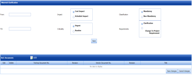


6.21.3 Print a Technical Query Report
If you want to print a technical query report, click (print icon) provided in the Report column of the Technical Query Report page. See Fig 6.22.
6.21.4 Attach a File into a Technical Query Report
If you want to attach any file with any technical query report listed in the Technical Query Report page, follow the procedures given in the topic “Attach a file into a client master drawing” in the Client Master Drawing section.
6.21.5 Edit Any Technical Query Report
If you want to edit any existing technical query report in the Technical Query Report page, do the following,
- Click
 (Edit icon) in the Edit column for the respective technical query report. See Fig 6.21.
A new window opens to edit the technical query report.
- Click any box where you want to edit the details, and then edit the details in the respective box.
-
Click Save.

6.21.6 Export Technical Query Report List
You can export a list of technical query reports added in the Technical Query Report page in the pdf and excel formats. To know how to export, see the topic, “Export Areas list” in the Area option.
6.22 Electrical Continuity Report
Electrical continuity test is a technique to check and verify the current flow in the metal paths. The Electrical Continuity Report tab in the Structural menu used to add an electrical continuity report after the completion of electrical continuity test.
If you want to add an electrical continuity report, do the following,
- Click the Electrical Continuity Report Tab.
The Electrical Continuity Report page opens.

Figure 6.22: Electrical Continuity Report page
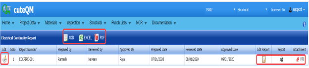
6.22.1 Add an Electrical Continuity Report
If you want to add an electrical continuity report,
- Click
 (ADD button) in the Electrical Continuity Report See Fig 6.22.
A new window opens to add an electrical continuity report.

 Tip: A report number for a new electrical continuity report will be updated automatically in the Report Number box.
 - In the Prepared By box, enter the name a person who has prepared the electrical continuity report.
-
In the Prepared Date box, enter the prepared date of the electrical continuity report.
- In the Reviewed By box, enter the name a person who has reviewed the electrical continuity report.
-
In the Reviewed Date box, enter the reviewed date of the electrical continuity report.
-
In the Approved By box, enter the name a person who has approved the electrical continuity report.
- In the Approved Dat ebox, enter the approved date of the electrical continuity report.
-
Click Save.

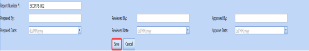

The electrical continuity report is successfully added. Once you have added the electrical continuity report, you must add the details for the added report.
6.22.2 Add Electrical Continuity Report Details
- Click
 (Edit icon) in the Edit Report column of the Electrical Continuity Report See Fig 6.22.
The Electrical Continuity Parameters, Electrical Continuity, and Report Photos windows open in the Electrical Continuity Report page.

 Tip: If you want to add any notes for the electrical continuity report, you can add in the Notes window provided in the Electrical Continuity Report page.
 - If you want to add the electrical continuity parameters in the Electrical Continuity Parameters window, do the following,
-
-
- In the Item Measured box, enter the number of items, which are measured for electrical continuity.
-
In the Procedure No box, enter the electrical continuity procedure number.
-
Click Save.
-
-
- If you want to add the electrical continuity details in the Electrical Continuity window, do the following,
-
-
- Click
 (ADD button) in the Electrical Continuity window.
Boxes opens in the respective columns to add the electrical continuity details.
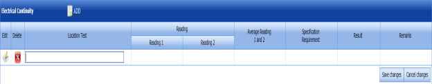
-
In the Location Test column, enter the location test detail.
- In the Reading column, enter the electrical continuity reading values for the respective Reading 1 and Reading 2.
- In the Average Reading 1 and 2columns, enter the average reading value.
-
In the Specification Requirement column, enter the specification requirement detail.
-
In the Result column, enter the result of the electrical continuity test.
-
In the Remarks column, enter you remarks if any.
-
Click Save Changes.
- Click
-
-
- If you want to add the report photos in the Report Photos window, do the following,
-
-
-
Click
 (ADD button) in the Report Photos window.
-
Click
 (Browse button) to browse a photo stored in your computer.
 -
Click Upload.
The selected photo will be updated.
-
-
-

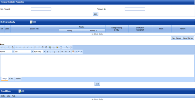


6.22.3 Print an Electrical Continuity Report
If you want to print an electrical continuity report, click (print icon) provided in the Report column of the Electrical Continuity Report page. See Fig 6.22.
6.22.4 Attach a File into an Electrical Continuity Report
If you want to attach any file with any electrical continuity report listed in the Electrical Continuity Report page, follow the procedures given in the topic “Attach a file into a client master drawing” in the Client Master Drawing section.
6.22.5 Edit Any Electrical Continuity Report
If you want to edit any existing electrical continuity report in the Electrical Continuity Report page, do the following,
- Click
 (Edit icon) in the Edit column for the respective electrical continuity report. See Fig 6.22.
A new window opens to edit the electrical continuity report.
-
Click any box where you want to edit the details, and then edit the details in the respective box.
-
Click Save.

6.22.6 Export Electrical Continuity Report List
You can export a list of electrical continuity reports added in the Electrical Continuity Report page in the pdf and excel formats. To know how to export, see the topic, “Export Areas list” in the Area option.
6.23 Joint Summary Report
The Joint Summary report tab in the Structural menu used to view a joint summary report. If you want to see a joint summary report,
- Click the Joint Summary Report tab.
A list of joint summary reports opens.
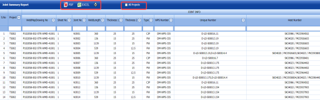
Figure 6.23: Joint Summary Report page
 Tip: If you want to view a joint summary report for all projects, click the check box provided with the All Projects option.


6.23.1 Export Joint Summary Report List
You can export a list of joint summary reports in the Joint Summary Report page in the pdf and excel formats. To know how to export, see the topic, “Export Areas list” in the Area option.
6.24 Joint Status Report (Skid)
The Joint Status Report (Skid) tab in the Structural menu helps you to view a joint status report (Skid) based on an inspection status report.
If you want to view a joint status report (Skid),
- Click the Joint Status Report (Skid) tab.
A joint status report (Skid) opens.

Figure 6.24: Joint Status Report (Skid) page
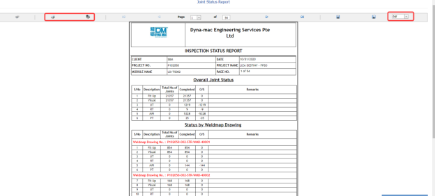
6.24.1 Print a Joint Status Report (Skid)
If you want to print a joint status report (Skid), use  and
and  (print icons) provided in the Joint Status Report (Skid) page. See Fig 6.24.
- If you want to print the current page of the joint status report (Skid), click
 (print icon including the page number).
 -
If you want to print all the pages of the joint status report (Skid), click
 (print icon).


6.24.2 Export Joint Status Report (Skid) List
You can export a joint status report (Skid) in the Joint Status Report (Skid) page in various formats by using the option  provided in the upper right corner of the Joint Status Report (Skid) page.
6.25 Joint Status Report (Project)
The Joint Status Report (Project) tab in the Structural menu helps you to view a joint status report (project) depends on the project type.
If you want to view a joint status report (project),
- Click the Joint Status Report (Project) tab.
A joint status report (project) opens.
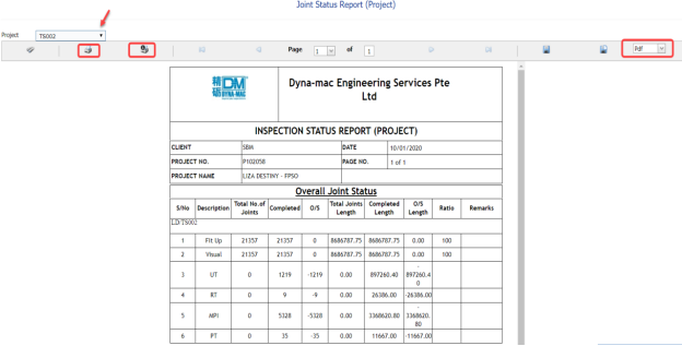
Figure 9.25: Joint Status Report (Project) page
-
In the Project box, select a project for which you want to view a joint status report (project), from a drop-down list.
A joint status report (project) opens for the selected project.

6.25.1 Print a Joint Status Report (Project)
If you want to print a joint status report (project), use and
and  (print icons) provided in the Joint Status Report (Project) page. See Fig 6.25.
- If you want to print the current page of the joint status report (project), click
 (print icon including the page number).
 -
If you want to print all the pages of the joint status report (project), click
 (print icon).


6.25.2 Export Joint Status Report (Project) List
You can export a joint status report (project) in the Joint Status Report (Project) page in various formats by using the option provided in the upper right corner of the Joint Status Report (Project) page.
6.26 Joint Status Report (Weekly)
The Joint Status Report (Weekly) tab in the Structural menu helps you to view a joint status report (Weekly) on a weekly basis.
If you want to view a joint status report (Weekly),
- Click the Joint Status Report (Weekly) tab.
A joint status report (Weekly) opens.

Figure 6.26: Joint Status Report (Weekly) page
-
In the From Date and To Date boxes, select the from and to dates in respectively.
-
Click Go.
A joint status report (Weekly) opens for the selected dates.
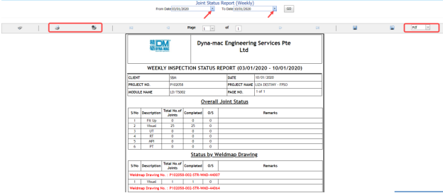
6.26.1 Print a Joint Status Report (Weekly)
If you want to print a joint status report (Weekly), use  and
and  (print icons) provided in the Joint Status Report (Weekly) page. See Fig 6.26.
- If you want to print the current page of the joint status report (Weekly), click
 (print icon including the page number).
 -
If you want to print all the pages of the joint status report (Weekly), click
 (print icon).


6.26.2 Export Joint Status Report (Weekly) List
You can export a joint status report (Weekly) in the Joint Status Report (Weekly) page in various formats by using the option  provided in the upper right corner of the Joint Status Report (Weekly) page.
6.27 Inspection Status Report
Inspection Status Report shows the overall inspection reports such as from fit-up inspection status to NDT inspection status.
If you want to view an inspection status report, do the following,
- Click the Inspection Status Report tab.
The Inspection Status Report page opens.

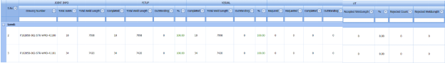

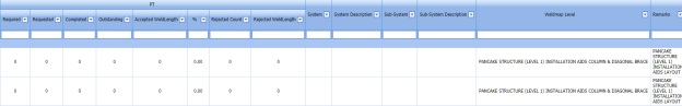
Figure 6.27: Inspection Status Report page
The Inspection Status Report page contains joint information, RFI fit-up, RFI weld VI, and NDT inspection status.
-
In the From Date and To Date boxes, select the from and to dates in respectively.
-
Click Search.
The inspection status report opens for the selected dates.
 Tip: If you want to view the inspection status report including the weld and NDT inspection date, click the check box provided with the Weld Date/ NDT Date option.

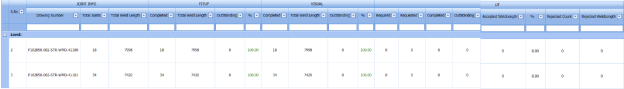
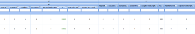


6.27.1 Print an Inspection Status Report
If you want to print an inspection status report, use (print icon) provided in the Inspection Status Report page. See Fig 6.27.
6.27.2 Export Inspection Status Report List
You can export a list of inspection status report in the inspection Status Report page in the pdf and excel formats. To know how to export, see the topic, “Export Areas list” in the Area option.
6.28 Weld Traceability Record
The Weld Traceability Record tab in the Structural menu used to add and track a weld traceability record.
If you want add a weld traceability record, do the following,
- Click the Weld Traceability Record tab.
The Weld Traceability Record page opens.

Figure 6.28: Weld Traceability Record page
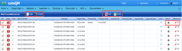
6.28.1 Add a Weld Traceability Record
If you want to add a weld traceability record, do the following,
- Click
 (ADD button) in the Weld Traceability Record page. See Fig 6.28.
A new window opens to add a weld traceability record.
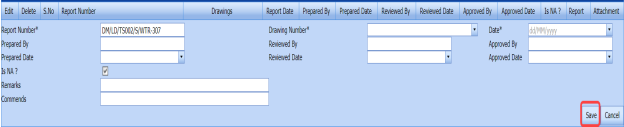
 Note: The field notified with a symbol (*) is mandatory. You must enter the relevant details in that fields before saving.
 Tip: A report number for a new weld traceability record will be updated automatically in the Report Number box.
 -
In the Drawing Number box, select a drawing number from a drop-down list.
-
In the Date box, enter the date of adding the weld traceability record.
-
In the Prepared By box, enter the name of a person who has prepared the weld traceability record.
- In the Prepared Date box, select the prepared date of the weld traceability record.
- In the Reviewed By box, enter the name of a person who has reviewed the weld traceability record.
-
In the Reviewed Date box, select the reviewed date of the weld traceability record.
-
In the Approved By boxes, enter the name of a person who has approved the weld traceability record.
- In the Approved Date box, select the approved date of the weld traceability record.
-
If you want to display Not Applicable (NA) in any field instead of leaving as an empty one, select the Is NA? check box.
- In the Remarks box, enter your remarks if any.
-
In the Comments box, enter your comments if any.
-
Click Save.
The weld traceability record is successfully added.


6.28.2 Print a Weld Traceability Report
If you want to print a weld traceability report, click (print icon) provided in the Report column in the Weld Traceability Record page. See Fig 6.28.
6.28.3 Attach a File into a Weld Traceability Record
If you want to attach any file with the weld traceability record listed in the Weld Traceability Record page, follow the procedures given in the topic “Attach a file into a client master drawing” in the Client Master Drawing section.
6.28.4 Edit Any Weld Traceability Record
If you want to edit any existing weld traceability record in the Weld Traceability Record page, do the following,
- Click
 (Edit icon) in the Edit column for the respective weld traceability record. See Fig 6.28.
A new window opens to edit the weld traceability record.
- Click any box where you want to edit the details, and then edit the details in the respective box.
-
Click Save.

6.28.5 Export Weld Traceability Record List
You can export a list of weld traceability record added in the Weld Traceability Record page in the pdf and excel formats. To know how to export, see the topic, “Export Areas list” in the Area option.
6.28.6 Filter Any Weld Traceability Record
If you want to filter any weld traceability record from the list in the Weld Traceability Record page, you can use the  (FILTER button). To know how to filter, see the topic, ”Filter Any Area”.
6.29 Weld Rejection Rate
In Structural project, Weld Rejection Rate is the difference between the tested length and repair length of the welded material, which are calculated using RT and UT inspection. The Weld Rejection Rate is used to calculate the weld success rate.
The Weld Rejection Rate tab in the Structural menu shows a weld rejection rate report including weekly and cumulative weld success rate summary details.
If you want to view a weld rejection rate report,
- Click the Weld Rejection Rate tab.
The weld rejection rate report page opens.
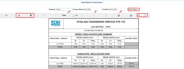
Figure 9.29: Weld Rejection Rate Report page
-
In the Project box, select a project for which you want to view a weld rejection rate report, from a drop-down list.
-
In the From Date and To Date boxes, select the from and to dates in respectively.
-
Click Show Report.
The weld rejection rate report opens for the selected project.
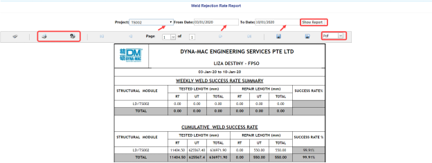
6.29.1 Print a Weld Rejection Rate Report
If you want to print a weld rejection rate report, use and
and  (print icons) provided in the Weld Rejection Rate Report page. See Fig 6.29.
- If you want to print the current page of the weld rejection rate report, click
 (print icon including the page number).
 -
If you want to print all the pages of the weld rejection rate report, click
 (print icon).


6.29.2 Export Weld Rejection Rate Report
You can export the weld rejection rate report in various formats by using the option  provided in the upper right corner of the Weld Rejection Rate Report page.
6.30 Weld Rejection Rate (MPI)
In Structural project, Weld Rejection Rate (MPI) is the difference between the tested length of and repair length of the Complete Joint Penetration (CJP) and Fillet welding materials, which are calculated using MPI inspection. The Weld Rejection Rate is used to calculate the weld success rate.
The Weld Rejection Rate (MPI) tab in the Structural menu shows a weld rejection rate report including weekly and cumulative weld success rate summary details.
If you want to view a weld rejection rate report,
- Click the Weld Rejection Rate (MPI) tab.
The Weld Rejection Rate Report page opens.
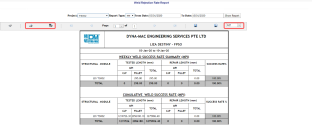
-
In the Project box, select a project for which you want to view a weld rejection rate report, from a drop-down list.
-
In the Report Type box, select the report type from a drop-down list.
-
In the From Date and To Date boxes, select the from and to dates in respectively.
-
Click Show Report.
The weld rejection rate report opens for the selected project.
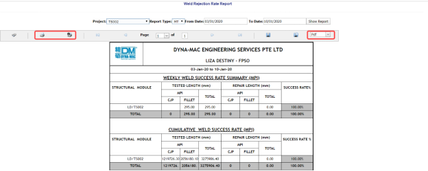
6.30.1 Print a Weld Rejection Rate Report
If you want to print a weld rejection rate report, use  and
and  (print icons) provided in the Weld Rejection Rate Report page. See Fig 6.30.
- If you want to print the current page of the weld rejection rate report, click
 (print icon including the page number).
 - If you want to print all the pages of the weld rejection rate report, click
 (print icon).


6.30.2 Export Weld Rejection Rate Report
You can export the weld rejection rate report in various formats by using the option  provided in the upper right corner of the Weld Rejection Rate Report page.
6.31 Inspection Progress Status Report
The Inspection Progress Status Report tab in the Structural menu helps you to view an inspection progress status report depends on the project type.
If you want to view an inspection progress status report,
- Click the Inspection Progress Status Report tab.
The inspection progress status report page opens.

Figure 6.31: Inspection Progress Status Report page
- In the Project box, select a project for which you want to view an inspection progress status report, from a drop-down list.
-
Click Show Report.
The inspection progress status report opens for the selected project.
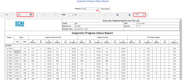
6.31.1 Print an Inspection Progress Status Report
If you want to print an inspection progress status report, use  and
and  (print icons) provided in the Inspection Progress Status Report page. See Fig 6.31.
- If you want to print the current page of the inspection progress status report, click
 (print icon including the page number).
 -
If you want to print all the pages of the inspection progress status report, click
 (print icon).


6.31.2 Export Inspection Progress Status Report
You can export the inspection progress status report in the Inspection Progress Status Report page in various formats by using the option  provided in the upper right corner of the Inspection Progress Status Report page.
6.32 Welder Performance Report
Welder performance report used to view the welder performance details. If you want to view a welder performance report, do the following,
- Click the Welder Performance tab.
The Welder Performance Report page opens.
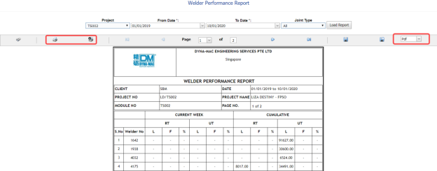
Figure 6.32: Welder Performance Report page
-
In the Project box, select a project for which you want to view a welder performance report, from a drop-down list.
-
In the From Date and To Date boxes, select the from and to dates in respectively.
-
In the Joint type box, select the joint type from a drop-down list.
-
Click Load Report.

The welder performance report opens for the selected project.
6.32.1 Print a Welder Performance Report
If you want to print a welder performance report, use  and
and  (print icons) provided in the Welder Performance Report page. See Fig 6.32.
- If you want to print the current page of the welder performance report, click
 (print icon including the page number).
 -
If you want to print all the pages of the welder performance report, click (print icon).

6.32.2 Export Welder Performance Report
You can export the welder performance report in various formats by using the option  provided in the upper right corner of the Welder Performance Report page.
6.33 Welder Statistic Report
Welder Statistics Report shows the statistical data of the welders. If you want to view a welder statistics report, do the following,
- Click the Welder Statistic Report tab in the Structural meu.
The Welder Statistic Report page opens.

Figure 9.33: Welder Statistic Report page
-
In the From Date and To Date boxes, select the from and to dates in respectively.
-
Click Load Report.
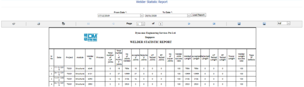
The welder statistic report opens for the selected dates.
6.33.1 Print a Welder Statistic Report
If you want to print a welder statistic report, use  and
and  (print icons) provided in the Welder Statistic Report page. See Fig 6.33.
- If you want to print the current page of the welder statistic report, click
 (print icon including the page number).
 -
If you want to print all the pages of the welder statistic report, click
 (print icon).


6.33.2 Export Welder Statistic Report
You can export the welder statistic report in various formats by using the option  provided in the upper right corner of the Welder Statistic Report page.
6.34 Joint Summary Report (Detailed)
Joint Summary Report (Detailed) used to track the detailed weld joints summary. Do the following steps to view a joint summary report,
- Click the Joint Summary Report (Detailed) tab. The Welding Summary Report page opens.
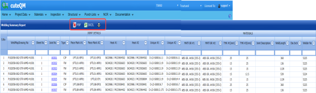
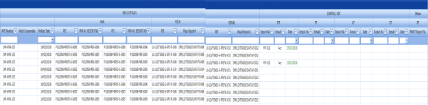
Figure 6.34: Welding Summary Report page


6.34.1 Edit Joint Details
If you want to edit the joint details in the welding summary details,
- Click the respective joint number in the Joint No column of the Welding Summary Report page.
The Joint Details window opens

- Click
 (Edit icon) in the Edit column for the respective joint numbers of the columns where you want to make changes in the thickness of the weld joint, piece mark number, and heat number.
 -
Edit the details in the respective columns.
-
Click Save.
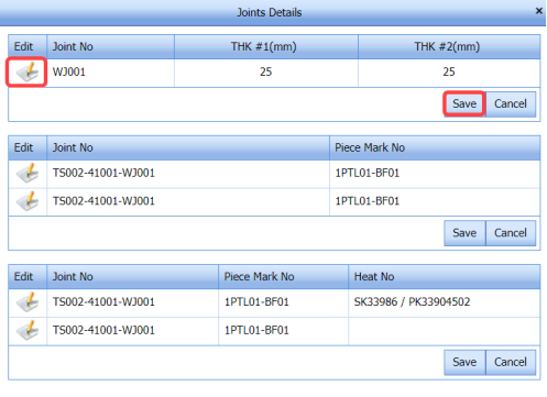

6.34.2 Print a Welding Summary Report
If you want to print a welding summary report, use  (print icon) provided in the Welding Summary Report page. See Fig 6.35.
6.34.3 Export Welding Summary Report List
You can export a list of welding summary reports added in the Welding Summary Report page in the pdf and excel formats. To know how to export, see the topic, “Export Areas list” in the Area option.
No Comments