
Project Data
3.0 Project Data
The Project Data menu in the cuteQM app helps you to add the master data and the personal data for the piping project. Once you click the Project Data menu, the following tabs open,
3.1 Piping and Instrumentation Diagram (P&ID)
P&ID is a schematic diagram which shows the functional relationship of piping, instrumentation, and system equipment components. The P&ID includes mechanical equipment with names and numbers, Process piping, sizes and identification, Flow directions, and so on.
The P&ID tab in the Project Data menu helps you to add a P&ID. If you want to navigate to P&ID, do the following,
- Click P&ID in the Project Data menu.
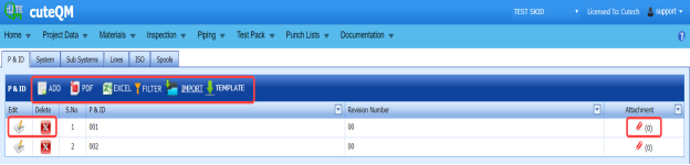
The P&ID page opens.

Figure 3.1: P&ID page
3.1.1 Add a P&ID
If you want to add a new P&ID, do the following steps,
-
Click
 (ADD button) in the P&ID page. See Fig 3.1.
 A new window opens to add a new P&ID.
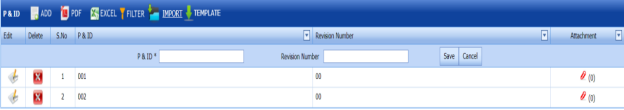
 Note: The field notified with a symbol (*) is mandatory. You must enter the relevant details in that fields before saving.
 -
In the P&ID box, enter the P&ID number.
-
In the Revision Number box, enter the revision number for the P&ID.
- Click Save.
The P&ID is successfully added and listed in the P&ID page.


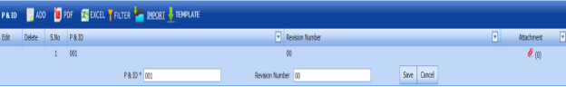
3.1.2 Edit a P&ID
If you want to edit any existing P&ID in the P&ID page,
- Click
 (Edit icon) of the respective P&ID. See Fig 3.1.
 - The P&ID page shows the details of the P&ID.

- Edit the details where you want.
- Click Save.

3.1.3 Delete a P&ID
If you want to delete any existing P&ID in the P&ID page,
-
Click
 (Delete icon) of the respective P&ID. See Fig 3.1.
 You receive a notification message “Confirm Delete?”.
-
Click OK.
The selected P&ID will be deleted from the P&ID page.

3.1.4 Export P&ID list
You can export a list of P&IDs added in the P&ID page in both the pdf and excel formats.
-
If you want to export the P&ID list in the pdf format, click
 (PDF button).
 The P&ID list will be downloaded as a pdf file.
-
If you want to export the P&ID list in the excel format, click
 (Excel button).
 The P&ID list will be downloaded as an excel file.


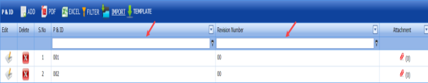
3.1.5 Filter a P&ID
If you want to filter any specific P&ID in the P&ID page, do the following,
-
Click
 (FILTER button) located on the P&ID See Fig 3.1.
Once you clicked the Filter button, the filter box opens for the P&ID and Revision Number columns.

-
Enter relevant detail in the respective column’s filter box to filter any P&ID.

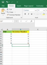
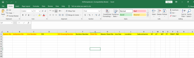
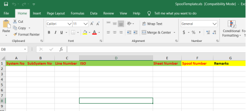
3.1.6 Import Multiple P&IDs
If you want to import multiple P&IDs together, do the following,
-
Click
 (TEMPLATE button). See Fig 3.1.
An excel worksheet will be downloaded with a predefined template to enter the details of P&IDs.
-
Enter the required P&ID details in the respective columns of the excel worksheet.
- Once you have added the P&ID details in the excel worksheet, save the excel worksheet on your computer.
-
Click
 (IMPORT button). See Fig 3.1.
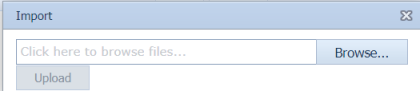
 A new window opens for importing the excel worksheet saved on your computer.

-
Click
 (Browse button) to select the excel worksheet to be uploaded.
 -
Select the excel worksheet you want to upload from your computer.
-
Click
 (Upload button) to export the P&IDs that are included in the excel worksheet.
 The details of the P&IDs in the worksheet will be displayed in the P&ID page.


3.1.7 Attach a File into a P&ID
If you want to attach a file for example drawing, with any existing P&ID listed in the P&ID page,
-
Click
 (Attach icon) provided against the respective P&ID in the P&ID page.
The File Upload (P&ID - Drawings) page opens.
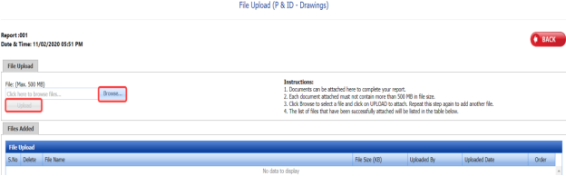
 Note: Before uploading any file, read the instructions given in the File Upload (P&ID - Drawings) page.
 -
Click
 (Browse button).
 - Select a file which you want to upload from your computer.
-
Click
 (Upload button) to attach the file.
The uploaded file will be displayed in the File Upload table.


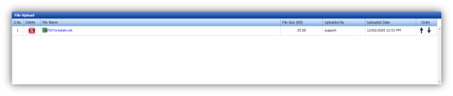
3.2 System
You can add the details of systems to be used in the piping project by using the Systems tab in the Project Data menu. If you want to navigate to Systems,
-
Click Systems in the Project Data menu.
The System page opens.
Figure 3.2: System page
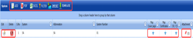
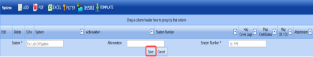
3.2.1 Add a System
If you want to add a new system, do the following steps,
-
Click
 (ADD button) in the System See Fig 3.2.
A new window opens to add a new system.

 Note: The fields notified with a symbol (*) are mandatory. You must enter the relevant details in that fields before saving.
 - In the System box, enter the system name.
- In the Abbreviation box, enter the abbreviation for the system name.
-
In the System Number box, enter the system number.
- Click Save.
The system is successfully added and listed in the System page.
 Note:
Note: -
-
If you want to map cover page for any added system, click the respective
 (Add icon)
 provided in the Map Cover Page column and add the cover pages.
-
If you want to map certificates for any added system, click the respective
 (Add icon)
provided in the Map Certificates column and add the cover pages.
-
If you want to map Check Record/Check Sheet (CR/CS) for any added system,
click the respective
 (Add icon) provided in the Map CR/CS column and add the cover pages.
-
-


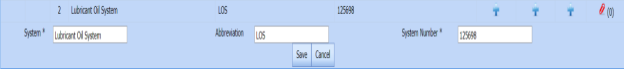
3.2.2 Edit a System
If you want to edit any existing system in the System page,
-
Click
 (Edit icon) of the respective System. See Fig 3.2.
The System page shows the details of the selected system.

-
Edit the details where you want.
-
Click Save.

3.2.3 Delete a System
If you want to delete any existing system in the System page, you can use (Delete icon) provided in the System page. To know how to delete, see the topic, “Delete P&ID”.
3.2.4 Export System List
You can export a list of systems added in the System page in both the pdf and excel formats by using  (PDF button) and
  (Excel button). To know how to export, see the topic, “Export P&ID list”.
3.2.5 Filter a System
If you want to filter any specific system in the System page, you can use  (FILTER button) located on the System page. To know how to filter, see the topic, “Filter P&ID”.
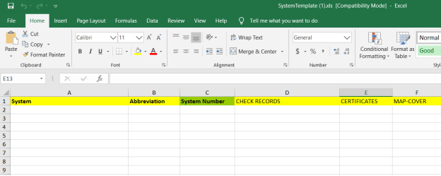
3.2.6 Import Multiple Systems
If you want to import multiple systems together, do the following,
-
Click
 (TEMPLATE button). See Fig 3.2.
An excel worksheet will be downloaded with a predefined template to enter the details of systems.

-
Enter the required system details in the respective columns of the excel worksheet.
-
Once you have added the system details in the excel worksheet, save the excel worksheet on your computer.
-
Click
 (IMPORT button). See Fig 3.2.
A new window opens for importing the excel worksheet saved on your computer.

-
Click
 (Browse button) to select the excel worksheet to be uploaded.
 - Select the excel worksheet you want to upload from your computer.
-
Click
 (Upload button) to export the systems that are included in the excel worksheet.
The details of the systems in the worksheet will be displayed in the System page.


3.2.7 Attach a File into a System
If you want to attach any file with any system listed in the System page, you can attach the file by using (Attach icon) in the Attachment column. To know how to attach, follow the procedures given in the topic “Attach a file into P&ID”.
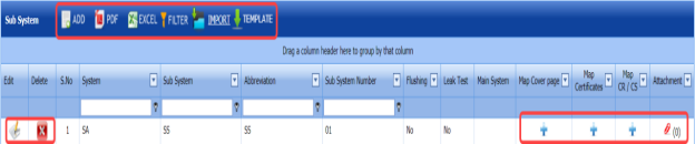
3.3 Sub System
The Sub Systems tab in the Project Data menu helps you to add the details of sub systems to be in used in the piping project. If you want to navigate to Sub Systems,
-
Click Sub Systems in the Project Data menu.
The Sub Systems page opens.

Figure 6.3: Sub System page
3.3.1 Add a Sub System
If you want to add a new sub system, do the following steps,
-
Click
 (ADD button) in the Sub System See Fig 3.3.
A new window opens to add a new sub system.
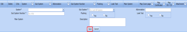
 Note: The fields notified with a symbol (*) are mandatory. You must enter the relevant details in that fields before saving.
 - In the System box, select a system from a drop-down list.
- In the Sub System box, select a sub system from a drop-down list.
- In the Abbreviation box, enter the abbreviation for the sub system.
- In the Sub System Number box, enter the sub system number.
-
If the added subsystem needs to be flushed, select Yes in the Flushing option otherwise select No.
- If there is need to perform the leakage test for the added subsystem, select Yes in the Leak Test option otherwise select No.
- In the Description box, enter the description for the added sub system.
- Click Save.
The sub system is successfully added and listed in the Sub System page.


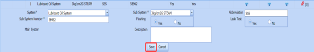
3.3.2 Edit a Sub System
If you want to edit any existing sub system in the Sub System page,
-
Click
 (Edit icon) of the respective sub system. See Fig 3.3.
The Sub System page shows the details of the selected sub system.

- Edit the details where you want.
-
Click Save.

3.3.3 Delete a Sub System
If you want to delete any existing sub system in the Sub System page, you can use  (Delete icon) provided in the Sub System page. To know how to delete, see the topic,
3.3.4 Export Sub System List
You can export a list of sub systems added in the Sub System page in both the pdf and excel formats by using  (PDF button) and
  (Excel button). To know how to export, see the topic, “Export P&ID list”.
3.3.5 Filter a Sub System
If you want to filter any specific sub system in the Sub System page, you can use  (FILTER button) located on the Sub System page. To know how to filter, see the topic, “Filter P&ID”.
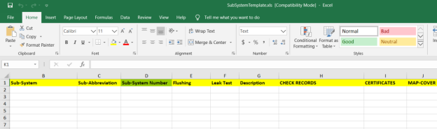
3.3.6 Import Multiple Sub Systems
If you want to import multiple sub systems together, do the following,
-
Click
 (TEMPLATE button). See Fig 3.3.
An excel worksheet will be downloaded with a predefined template to enter the details of sub systems.
-
Enter the required sub system details in the respective columns of the excel worksheet.
- Once you have added the sub system details in the excel worksheet, save the excel worksheet on your computer.
-
Click
 (IMPORT button). See Fig 3.3.
A new window opens for importing the excel worksheet saved on your computer.

-
Click
 (Browse button) to select the excel worksheet to be uploaded.
 - Select the excel worksheet you want to upload from your computer.
-
Click
 (Upload button)to export the sub systems that are included in the excel worksheet.
 The details of the sub systems in the worksheet will be displayed in the Sub System page.


3.3.7 Attach a File into a Sub System
If you want to attach any file with any sub system listed in the Sub System page, you can attach the file by using  (Attach icon) in the Attachment column. To know how to attach, follow the procedures given in the topic. “Attach a file into P&ID”.
3.4 Lines
The Lines tab in the Project Data menu helps you to add the details of lines to be in used in the piping project. If you want to add Lines,
- Click Lines in the Project Data menu,
The Lines page opens.
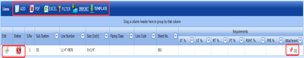
Figure 3.4: Lines page

3.4.1 Add a Line
If you want to add a line, do the following steps,
-
Click
 (ADD button) in the Lines page. See Fig 3.4.
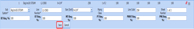
A new window opens to add new lines.
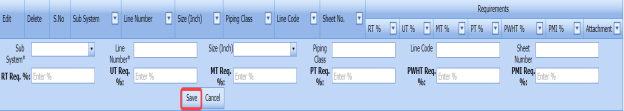
 Note: The fields notified with a symbol (*) are mandatory. You must enter the relevant details in that fields before saving.
 - In the Sub System box, select a sub system from a drop-down list.
- In the Line Number box, enter the line number.
- In the Size box, select the size of the line.
- In the Piping Class box, enter the piping class name.
- In the Line Code box, enter the line code.
- In the Sheet Number box, enter the sheet number.
- In the RT Req. % box, enter the requirement percentage of RT.
- In the UT Req. % box, enter the requirement percentage of UT.
- In the MT Req. % box, enter the requirement percentage of MT.
- In the PT Req. %box, enter the requirement percentage of PT.
- In the PWHT Req. %box, enter the requirement percentage of PWHT.
- In the PMI Req. %box, enter the requirement percentage of PMI.
 Note: The RT, UT, MT, PT, PWHT, and PMI Requirements (%) should be filled with valid numerical numbers. The joint testing will be performed based on the value given by you, for example, if you enter 100 % of requirement, which means 100 % of the joints will be tested. If you enter 0 %, none of joints will be tested.
 -
Click Save.
The line is successfully added and listed in the Lines page.


3.4.2 Edit a Line
If you want to edit any existing line in the Lines page,
-
Click
 (Edit icon) of the respective sub system. See Fig 3.4.
The Lines page shows the details of the selected line.
-
Edit the details where you want.
-
Click Save.


3.4.3 Delete a Line
If you want to delete any existing line in the Lines page, you can use  (Delete icon) provided in the Lines page. To know how to delete, see the topic, “Delete P&ID”.
3.4.4 Export Line List
You can export a list of lines added in the Lines page in both the pdf and excel formats by using  (PDF button) and
  (Excel button). To know how to export, see the topic “Export P&ID list”.
3.4.5 Filter a Line
If you want to filter any specific line in the Lines page, you can use  (FILTER button) located on the Lines page. To know how to filter, see the topic, “Filter P&ID”.
3.4.6 Import Multiple Lines
If you want to import multiple lines together, do the following,
-
Click
 (TEMPLATE button). See Fig 3.4.
An excel worksheet will be downloaded with a predefined template to enter the details of lines.
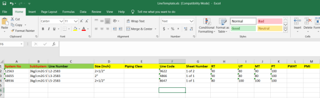
- Enter the required line details in the respective columns of the excel worksheet.
-
Once you have added the line details in the excel worksheet, save the excel worksheet on your computer.
-
Click
 (IMPORT button). See Fig 3.4.
A new window opens for importing the excel worksheet saved on your computer.

-
Click
 (Browse button) to select the excel worksheet to be uploaded.
 - Select the excel worksheet you want to upload from your computer.
-
Click
 (Upload button) to export the lines that are included in the excel worksheet.
The details of the lines in the worksheet will be displayed in the Lines page.


3.4.7 Attach a File into a Line
If you want to attach any file with a line listed in the Lines page, you can attach the file by using  (Attach icon) in the Attachment column. To know how to attach, follow the procedures given in the topic “Attach a file into P&ID”.
3.5 Isometric (ISO) Drawings
An isometric drawing is a detailed orthographic drawing that represents the details of 3D structure of the piping system in a 2D format for fabrication of the pipe. If you want to navigate to ISO,
- Click ISO Drawings in the Project Data menu.
The ISO page opens.
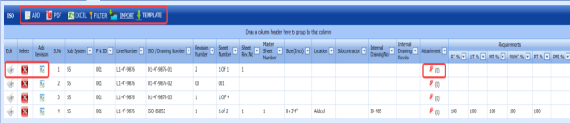
Figure 3.5: ISO page

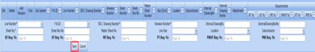
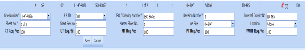
3.5.1 Add an ISO Drawing
If you want to add a new ISO drawing, do the following steps,
-
Click
 (ADD button) in the ISO page. See Fig 3.5.
 A new window opens to add a new ISO drawing.

 Note: The fields notified with a symbol (*) are mandatory. You must enter the relevant details in that fields before saving.
 - In the Line Number box, select the line number from a drop-down list.
- In the P&ID box, select the P&ID from a drop-down list.
- In the ISO Drawing Number box, enter the number for an ISO drawing you want to add.
- In the Revision Number box, enter the revision number for the ISO drawing.
-
In the Internal Drawing No box, enter the internal drawing number of the isometric drawing.
- In the Internal Drawing Rev. No box, enter the revision number for the internal drawing.
- In the Sheet No box, enter the sheet number.
- In the Sheet Rev. No box, enter the sheet revision number.
- In the Master Sheet No box, enter the master sheet number.
- In the Line Size box, select the line size from a drop-down list.
- In the Location box, select the location from a drop-down list.
- In the Sub Contractor box, select the sub-contractor from a drop-down list.
- In the RT Req. % box, enter the requirement percentage of RT.
- In the UT Req. % box, enter the requirement percentage of UT.
- In the MT Req. % box, enter the requirement percentage of MT.
- In the PT Req. % box, enter the requirement percentage of PT.
- In the PWHT Req. % box, enter the requirement percentage of PWHT.
- In the PMI Req. % box, enter the requirement percentage of PMI.
 Note: The RT, UT, MT, PT, PWHT, and PMI Requirements (%) should be filled with valid numerical numbers. The joint testing will be performed based on the value given by you, for example, if you enter 100 % of requirement, which means 100 % of the joints will be tested. If you enter 0 %, none of joints will be tested.
 - Click Save.
The ISO drawing is successfully added and listed in the ISO page.


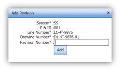
3.5.2 Add Revision for ISO Drawing
Once you have added the ISO drawing, the ISO page shows  (Revision icon) for the added ISO drawing. You can add multiple revisions for the added ISO by using this revision icon.
-
Click
 (Revision icon) of the respective ISO drawing.
The Add Revision box opens.
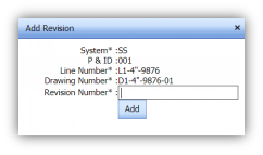
- In the Revision Number box, enter the revision number.
- Click Add.
The revision for the ISO drawing will be added and listed in the ISO page.

3.5.3 Edit an ISO Drawing
If you want to edit any existing ISO drawing in the ISO page,
-
Click
 (Edit icon) of the respective sub system. See Fig 3.5.
The ISO page shows the details of the selected ISO drawing.
- Edit the details where you want.
- Click Save.


3.5.4 Delete an ISO Drawing
If you want to delete any existing ISO drawing in the ISO page, you can use  (Delete icon) provided in the ISO page. To know how to delete, see the topic, “Delete P&ID”.
3.5.5 Export ISO Drawings List
You can export a list of ISO drawings added in the ISO page in both the pdf and excel formats by using  (PDF button) and
  (Excel button). To know how to export, see the topic, “Export P&ID list”.
3.5.6 Filter an ISO Drawing
If you want to filter any specific ISO drawing in the ISO page, you can use  (FILTER button) provided on the ISO page. To know how to filter, see the topic, “Filter P&ID”.
3.5.7 Import Multiple ISO Drawings
If you want to import multiple ISO drawings together, do the following,
-
Click
 (TEMPLATE button). See Fig 3.5.
An excel worksheet will be downloaded with a predefined template to enter the details of ISO drawings.
-
Enter the required ISO drawing details in the respective columns of the excel worksheet.
-
Once you have added the ISO drawing details in the excel worksheet, save the excel worksheet on your computer.
-
Click
 (IMPORT button). See Fig 3.5.
A new window opens for importing the excel worksheet saved on your computer.

-
Click
 (Browse button) to select the excel worksheet to be uploaded.
 - Select the excel worksheet you want to upload from your computer.
-
Click
 (Upload button) to export the ISO drawings that are added in the excel worksheet.
The details of the ISO drawings in the worksheet will be displayed in the ISO page.


3.5.8 Attach a File into an ISO Drawing
If you want to attach any file with an ISO drawing listed in the ISO page, you can attach the file by using  (Attach icon) in the Attachment column. To know how to attach, follow the procedures given in the topic “Attach a file into P&ID”.
3.6 Spools
A spool refers to a section of a piping system that is pre-fabricated as smaller segments with flanges and fittings. If you want to navigate to Spools,
- Click Spools in the Project Data.
The Spools page opens.
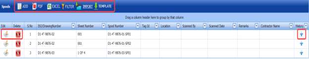
Figure 3.6: Spools page

3.6.1 Add a Spool
If you want to add a new spool, do the following steps,
-
Click
 (ADD button) in the Spools See Fig 3.6.
A new window opens to add a new spool.
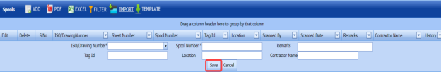
 Note: The fields notified with a symbol (*) are mandatory. You must enter the relevant details in that fields before saving.
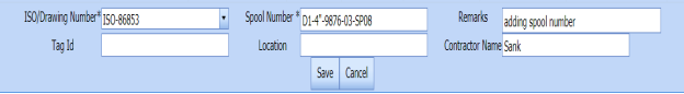
 - In the ISO Drawing Number box, select the ISO drawing number from a drop-down list.
- In the Spool Number box, enter the spool number for a spool you want to add.
- In the Tag Id box, enter the tag id number of the spool.
- In the Location box, select the location from a drop-down list.
- In the Contractor Name box, enter the contractor name.
- In the Remarks box, enter your remarks if any.
- Click Save.
The spool is successfully added and listed in the Spools page.


3.6.2 Edit a Spool
If you want to edit any existing spool in the Spools page,
-
Click
 (Edit icon)of the respective spool. See Fig 3.6.
The Spools page shows the details of the selected spool.
- Edit the details where you want.
- Click Save.


3.6.3 Delete a Spool
If you want to delete any existing spool in the Spools page, you can use  (Delete icon) provided in the Spools page. To know how to delete, see the topic, “Delete P&ID”.
3.6.4 Export Spool List
You can export a list of spools added in the Spools page in both the pdf and excel formats by using  (PDF button) and (Excel button). To know how to export, see the topic, “Export P&ID list”.
3.6.5 Filter a Spool
If you want to filter any spool in the Spools page, you can use  (FILTER button) provided on the Spools page. To know how to filter, see the topic, “Filter P&ID”.
3.6.6 Import Multiple Spools
If you want to import multiple spools together, do the following,
-
Click (TEMPLATE button). See Fig 3.6.
An excel worksheet will be downloaded with a predefined template to enter the details of spools.

-
Enter the required spool details in the respective columns of the excel worksheet.
-
Once you have added the spool details in the excel worksheet, save the excel worksheet on your computer.
-
Click
 (IMPORT button). See Fig 3.6.
A new window opens for importing the excel worksheet saved on your computer.

- Click (Browse button) to select the excel worksheet to be uploaded.
- Select the excel worksheet you want to upload from your computer.
-
Click (Upload button) to export the spool details that are added in the excel worksheet.
The details of the spools in the worksheet will be displayed in the Spools page.

3.7 Joints
A variety of joints are used in the assembly of pipes. Joints are the points where two or more pieces of materials for example pipes, are joined by welding. The Joints tab in the Project Data menu helps you add the joint details including joint number, material specification, welding type, and so on.
-
Click Joints in the Project Data menu.
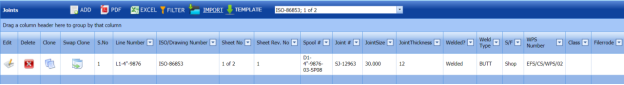
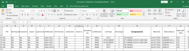
The Joints page opens.
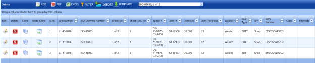
Due to insufficient space, the captured figure of the Joints page is split as four.
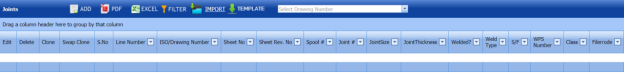
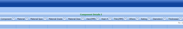
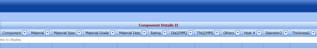
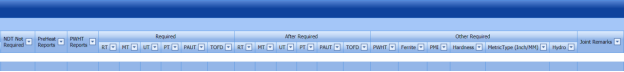
Figure 3.7: Joints page


3.7.1 Add a Joint
If you want to add a new joint, do the following steps,
- Click
 (ADD button) in the Joints See Fig 3.7.
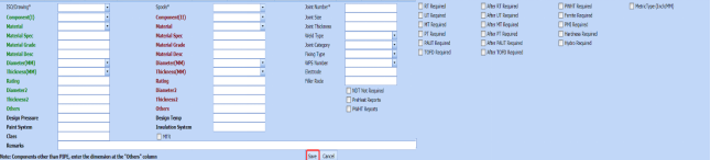
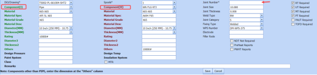
A new window opens to add a new joint.
 Note: The fields notified with a symbol (*) are mandatory. You must enter the relevant details in that fields before saving.
 - In the ISO Drawing Number box, select the ISO drawing number from a drop-down list.
- In the Spools box, select the spool from a drop-down list.
- In the Component (I) box, select the first component which you want to join.
- In the Material box, select the material of the first component.
- Enter the details of first component such as Material Spec, Material Grade, Material Desc, Diameter (MM), Thickness (MM), Rating, Diameter2, and Thickness2.
- In the Component (II) box, select the second component which you want joint.
- In the Material box, select the material of the second component.
- Enter the details of second component such as Material Spec, Material Grade, Material Desc, Diameter (MM), Thickness (MM), Rating, Diameter2, and Thickness2.
- If the component is other than pipe, enter the dimensions in Others
- In the Design Pressure box, enter the design pressure value.
- In the Paint System box, enter the paint system name.
- In the Design Temp box, enter the design temperature value.
- In the Insulation System box, enter the insulation system name.
- In the Joint Number box, enter the joint number.
- In the Joint Size box, enter the joint size range.
- In the Joint Thickness box, enter the joint thickness range.
- In the Weld Type box, select the welding type from a drop-down list.
- In the Joint Category box, select the joint category from a drop-down list.
- In the Fixing Type box, select the fixing type from a drop-down list.
- In the WPS Number box, select the WPS number from a drop-down list.
- In the Electrode box, enter the electrode name.
- In the Filler Rod box, enter the filler rod name.
-
If the NDT inspection is not required for the added joint, select the checkbox of the NDT Not Required option.
-
If the NDT inspection is required for the added joint, select the checkbox of the respective NDT types given for example RT Required, UT Required, and so on.
- In the Remarks box, enter your remarks if any.
- Click Save.
The joint is successfully added.
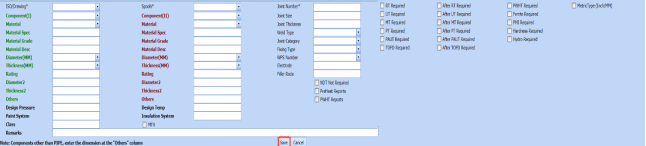
-
If you want view the added joint, select the respective drawing number from a drop-down list of the Select Drawing Number box in the upper side of the Joints page. and listed in the Joints page.
The joint for the selected drawing number will be displayed in the Joints page.


6.7.2 Clone a Joint
The Clone option provided in the Joints page used to add a new joint from previously added joint. If a joint to be added is having the same specifications of any joint already listed in the Joints page, you can add the new joint by using  (Clone icon).
- In the Joints page, find out the joint you want to clone.

-
Click
 (Clone icon) of the respective joint.
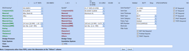
The Joints page shows the details of selected joint except joint number in the Joint Number box. See the below figure.
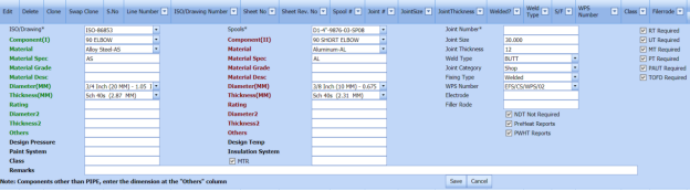
- If you want to change any details, you can change in the respective boxes.
- In the Joint Number box, enter the joint number for the new joint you want to add.
- Click Save.
The new joint is successfully added and listed in the Joints page.


3.7.3 Swap Clone Joint
The Swap Clone option provided in the Joints page used to add a new joint from previously added joint. When you do swap clone of any joint, the first and second components in the joint will be swapped each other.
- In the Joints page, find out the joint you want to swap clone.
- Click
 (Swap Clone icon) of the respective joint.
The Joints page shows the details of selected joint except joint number in the Joint Number box. The Component (I) and Component (II) will be swapped each other. See the below figure.

- If you want to change any details, you can change in the respective boxes.
- In the Joint Number box, enter the joint number for the new joint you want to add.
- Click Save.
The new joint is successfully added and listed in the Joints page.


3.7.4 Edit a Joint
If you want to edit any existing joint in the Joints page,
- Click (Edit icon) of the respective joint. See Fig 3.7.
The Joints page shows the details of the selected joint.

- Edit the details where you want.
- Click Save.
3.7.5 Delete a Joint
If you want to delete any existing joint in the Joints page, you can use  (Delete icon) provided in the Joints page. To know how to delete, see the topic, “Delete P&ID”.
3.7.6 Export Joints List
You can export a list of joints added in the Joints page in both the pdf and excel formats by using  (PDF button) and
  (Excel button). To know how to export, see the topic, “Export P&ID list”.
3.7.7 Filter a Joint
If you want to filter any joint in the Joints page, you can use  (FILTER button) provided on the Joints page. To know how to filter, see the topic, “Filter P&ID”.
3.7.8 Import Multiple Joints
If you want to import multiple joints together, do the following,
-
Click
 (TEMPLATE button). See Fig 3.7.
An excel worksheet will be downloaded with a predefined template to enter the details of joints.
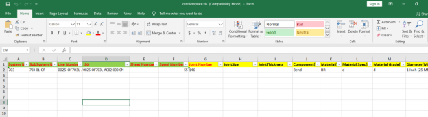
- Enter the required joint details in the respective columns of the excel worksheet.
-
Once you have added the joint details in the excel worksheet, save the excel worksheet on your computer.
-
Click
 (IMPORT button). See Fig 3.7.
A new window opens for importing the excel worksheet saved on your computer.

-
Click
 (Browse button) to select the excel worksheet to be uploaded.
 - Select the excel worksheet you want to upload from your computer.
-
Click
 (Upload button) to export the joint details that are added in the excel worksheet.
 The details of the joints in the worksheet will be displayed in the Joints page.


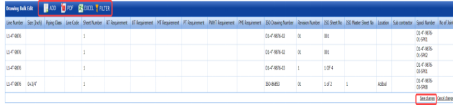
3.8 Drawing Bulk Edit
The Drawing Bulk Edit tab in the Project Data menu helps you to make changes in all the added ISO drawings together, where the ISO drawings are added using the ISO Drawings tab. This feature avoids the need to open each ISO drawing individually for making changes in the ISO drawings because you can make changes in all the ISO drawings together.
If you want to make changes in the ISO drawings together, do the following steps,
- Click Drawing Bulk Edit in the Project Data menu.
The Drawing Bulk Edit page opens with a list ISO drawing added in the ISO Drawings page.
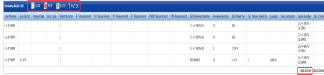
Figure 3.8: Drawing Bulk Edit page
- If you want make changes in any ISO drawing details, click on the respective detail, and edit.
- Click Save Changes.
The changes you have made here will be reflected in the respective ISO drawing in the ISO page.
 Note: You can also add a new ISO drawing by using (ADD Button) provided in the upper side of the Drawing Bulk Edit page.

3.8.1 Export Drawings After Editing
After making changes in the ISO drawings, you can export a list of drawings in the Drawing Bulk Edit page in both the pdf and excel formats by using  (PDF button) and
  (Excel button). To know how to export, see the topic, “Export P&ID list”.
3.8.2 Filter a Drawing
If you want to filter any ISO drawing in the Drawing Bulk Edit page, you can use (FILTER button) provided on the Drawing Bulk Edit page. To know how to filter, see the topic, “Filter P&ID”.
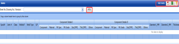
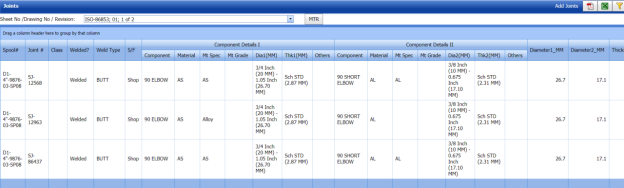
3.9 Joints Bulk Edit
The Joints Bulk Edit tab in the Project Data menu helps you to make changes in all the added joints together, where the joints are added using the Joints tab. This feature avoids the need to open each joint individually for making changes in the joint because you can make changes in all the joints together.
If you want to make changes in the joints together, do the following steps,
- Click Joints Bulk Edit in the Project Data menu.
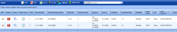
The Joints page opens with a list joints added in the Joints page.

Figure 3.9: Joints page
-
In the Sheet No/Drawing No/Revision box, select the drawing number from a drop-down list.
The joints corresponding to the selected drawing number will be displayed in the Joints page.

- If you want make changes in any joint, click on the respective joint detail, and edit.
- Click Save Changes.
The changes you have made here will be reflected in the respective joints in the Joints page.
 Note: You can also add a new joint by using provided in the upper right corner of the Joints Bulk Edit page.

3.9.1 Export Joints After Editing
After making changes in the joints, you can export a list of joints in the Joints page in both the pdf and excel formats by using  (PDF button) and
  (Excel button). To know how to export, see the topic, “Export P&ID list”.
3.9.2 Filter a Joint
If you want to filter any joint in the Joints page, you can use  (FILTER button) provided in the Joints page. To know how to filter, see the topic, “Filter P&ID”.
3.9.3 View Material Traceability Record (MTR)
You can view the MTR for added joints by using  (MTR button) provided in the Joints page. Once you click the MTR button, the page redirects you into the Material Traceability Record page.
3.10 Import from Excel - Masters
The Import from Excel – Masters tab helps you to upload master data for all fields instead of uploading data for each field individually.
If you want to import master data for different fields, do the following,
- Click Import from Excel – Masters in the Project Data
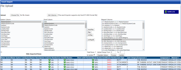
The File Upload page opens.
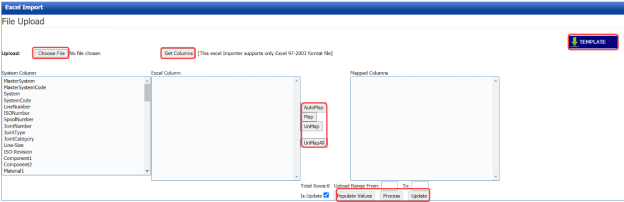
Figure 3.10: File Upload page
-
Download a template by using
 (TEMPLATE button) to enter the details of master data.
An excel worksheet will be downloaded with a pre-defined template to the details.

- Enter the relevant details in the respective column of the excel worksheet.
-
Click
 (Choose File button).
Once the file has been uploaded successfully, you receive a message, “Successfully uploaded”
-
Click
 (Get Columns button).
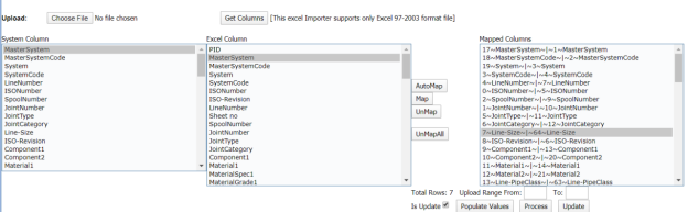
The columns added in the excel worksheet will be listed in the Excel Column field.
 Note: Make sure that the Excel Column field must have all the columns as in the System Column field.
 - To map the columns in the System Column and Excel Column fields, do one of the following,
-
If you want to map the columns Automatically, click
 (AutoMap button).
The columns will be mapped automatically and displayed in the Mapped Columns field.
- If you want to map each column manually, select the respective columns in both the System Columns and Each Excel Column fields and then click
 (Map button).
-
-
To un-map the columns in the Mapped Columns field, select the respective column and then click
 (UnMap button).
Once you have completed the mapping and un-mapping of columns, you must enter the range for uploading the data from the excel worksheet.
 Note: In the Total Rows field, the system indicates the total number of rows filled in the excel worksheet.
 Tip: You must enter the upload starting range as two in the Upload Range From field because a first row in the excel worksheet is having heading of the columns.
 - In the Upload Range From and To fields, enter the range of rows you want to upload from the excel worksheet.
-
Click
 (Populate Values button).
 -
Click
 (Process button).
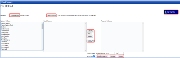
The system processes all the uploaded data and displays in the Excel Import page.

-
Click
 (Update button) to import the uploaded data.
The data will be successfully imported.


3.11 NDT Procedures
The NDT procedures tab in the Project Data menu helps you to add an NDT procedure. Once you have added the NDT procedure details you can add revision for the added NDT procedure. If you want to add an NDT procedure, do the following steps,
- Click NDT Procedures in the Project Data menu.
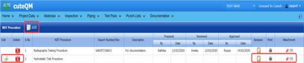
The NDT Procedure page opens.

Figure 3.11: NDT Procedure page
3.11.1 Add an NDT procedure
If you want to add an NDT procedure,
-
Click
 (ADD button) in the NDT Procedure page. See Fig 3.11.
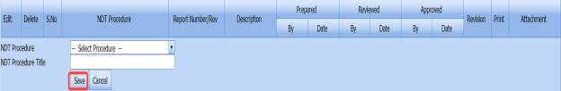
A new window opens to add an NDT procedure.

- In the NDT Procedure box, select the NDT procedure from a drop-down list.
- In the NDT Procedure Title box, enter the NDT procedure title.
- Click Save.
The NDT procedure is successfully added.

3.11.2 Add Details of NDT Procedure
Once you have added the NDT procedure, you must add the details of the added NDT procedure.
-
Click
 (Edit icon) of the respective NDT procedure in the NDT Procedure See Fig 3.11.
The NDT Procedure Revision window opens.

-
Click
 (ADD button) in the NDT Procedure Revision window.
A new window opens to add the NDT procedure details.
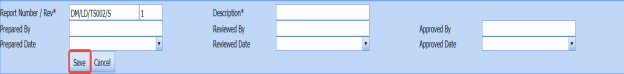
 Note: The fields notified with a symbol (*) are mandatory. You must enter the relevant details in that fields before saving.
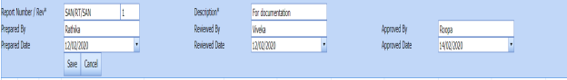
 Tip: A report number for the revision will be updated automatically in the Report Number/ Revision box.
 - In the Description box, enter the description for the NDT procedure.
- In the Prepared By box, enter the name a person who has prepared the NDT procedure.
- In the Prepared Date box, enter the prepared date of the NDT procedure.
- In the Reviewed By box, enter the name a person who has reviewed the NDT procedure.
- In the Reviewed Date box, enter the reviewed date of the NDT procedure.
- In the Approved By box, enter the name a person who has approved the NDT procedure.
- In the Approved Date box, enter the approved date of the NDT procedure.
- Click Save.
The NDT procedure details are successfully saved and listed in the NDT Procedure Revision window.

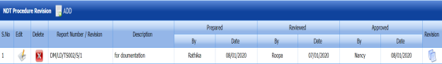


3.11.3 Add Revision for NDT Procedure
Once you have added the NDT procedure details, you can add revision for the added NDT procedures. You can add multiple revisions for one NDT procedure. To add revision,
-
Click
 (Revision icon) of the respective NDT procedure.
A new window opens with the details of existing NDT procedure.

-
Click Save.
The revision for the selected NDT procedure is added.

3.11.4 View an NDT Procedure Report
If you want to view an NDT procedure report, click (print icon) provided in the Print column of the NDT Procedure page. See Fig 3.11.
3.11.5 Attach a File into an NDT Procedure
If you want to attach any file with a NDT procedure listed in the NDT Procedure page, you can attach the file by using  (Attach icon) in the Attachment column. To know how to attach, follow the procedures given in the topic “Attach a file into P&ID”.
3.12 WPS in Project
WPS is a written instruction that specifies materials, consumables and edge preparations for a given joint. The WPS lists the pre- and post-weld operations including heat treatments; machining, grinding, and dressing of the weld.
The WPS in Project tab in the Project Data menu helps you to add a WPS report and assign the WPS to a project.
- Click WPS in Project tab in the Project Data menu.
The WPS by projects page opens with two fields such as WPS Summary and Assign WPS to Project.
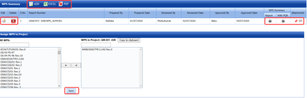
Figure 3.12: WPS in projects page

3.12.1 Add a WPS Summary Report
If you want to add a new WPS summary report, do the following,
-
Click
 (ADD button) in the WPS Summary field. See Fig 3.12.
A new window opens to add a WPS report.

 Tip: A report number for a new WPS report will be updated automatically in the Report Number box. If you want to change the report number, you can change.
 - In the Prepared By box, enter the name of a person who has prepared the WPS report.
- In the Reviewed By box, enter the name of a person who has reviewed the WPS report.
- In the Approved By box, enter the name of a person who has approved the WPS report.
- In the Prepared Date box, choose the prepared date of the WPS report.
- In the Reviewed Date box, choose the reviewed date of the WPS report.
- In the Approved Date box, choose the approved date of the WPS report.
- Click Save.
The WPS summary report is successfully added.


3.12.2 View a WPS Summary Report
If you want to view a WPS summary report, click (Print icon) provided in the WPS Summary Report column.
3.12.3 View a WPS Summary Report with PQR
If you want to view a WPS summary report with PQR, click (Print icon) provided in the WPS Summary with PQR column.
3.12.4 Attach a File into a WPS Summary Report
If you want to attach any file with any WPS summary report listed in the WPS Summary page, you can use  (Attach icon) provided in the Attachment column for the respective WPS summary report. To know how to attach, follow the procedures given in the topic “Attach a file into P&ID”.
3.12.5 Export WPS Summary Reports List
You can export a list of added WPS reports in the pdf and excel formats by using  (PDF button) and
  (Excel button). To know how to export, see the topic, “Export P&ID list”.
3.12.6 Assign a WPS to a Project
The Assign WPS to Project field in the WPS in projects page allows you to assign the WPS to the project. If you want to assign any WPS to the project, do the following,
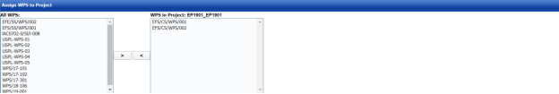
In the Assign WPS to Project field, the All WPS box displays a list of available WPS. The WPS in Project box displays a list of WPS that has been already assigned for the project.
- If you want to assign any WPS for the project, select the respective WPS in the ALL WPS box, and then click
 (Assign welder button).
The selected WPS will be assigned to the project.
- If you want to reject any WPS that has been assigned for the project, select the respective WPS in the WPS in Project box, and then click
 (Reject welder button).


3.13 Welders in Projects
The Welders in Projects tab in the Project Data menu helps you to assign welders for a project. You can add a welder report by using this tab. This tab also helps you to view a welder list and WPQ details.
-
Click Welders in Projects tab in Project Data menu.
The welders in projects page opens with four fields such as Welder Report, Assign Welder to Project, Welder List, and WPQ Details.
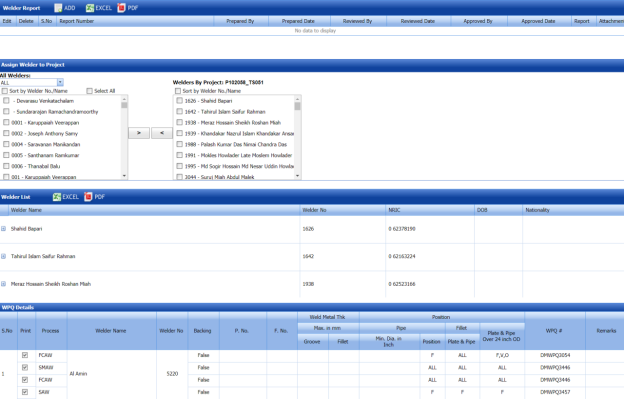
Figure 3.13: Welders in project page

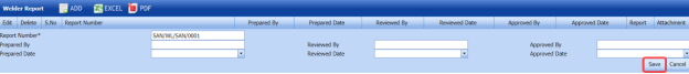
3.13.1 Add a Welder Report
If you want to add a welder report, do the following steps,
-
Click
 (ADD button) in the Welder Report See Fig 3.13.
A new window opens to add a welder report.

 Tip: A report number for a new welder report will be updated automatically in the Report Number box.
 - In the Prepared By box, enter the name of welder who has prepared the welder report.
- In the Received By box, enter the name of welder who has received the welder report.
- In the Approved By box, enter the name of welder who has approved the welder report.
- In the Prepared Date box, choose the prepared date of the welder report.
- In the Received Date box, choose the received date of the welder report.
- In the Approved Date box, choose the approved date of the welder report.
- Click Save.
The welder report is successfully added.


3.13.2 View a Welder Report
If you want to view a welder report, click (Print icon) provided in the Report column.
3.13.3 Attach a File into a Welder Report
If you want to attach any file with any welder report listed in the Welder Report window, you can use (Attach icon) provided in the Attachment column for the respective welder report. To know how to attach, follow the procedures given in the topic “Attach a file into P&ID”.
3.13.4 Export Welder Reports List
You can export a list of welder reports in the Welder Report field in both the pdf and excel formats by using  (PDF button) and
  (Excel button). To know how to export, see the topic, “Export P&ID list”.
3.13.5 Assign a Welder to a Project
The Assign Welder to Project field in the welders in projects page allows you to assign any welder to the particular project. If you want to assign any welder to the project, do the following,
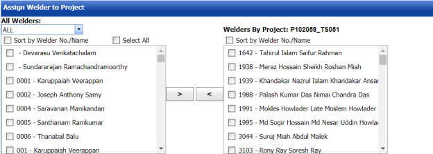
-
In the All Welders box, if you want to view all the welders, click ALL otherwise select the respective company’s welder group from a drop-down list to view their welders list.
Once you have selected the company’s welder group, the left-side box shows a list of welders. The right-side box shows a list of welders who has been already assigned for the project.
-
If you want to assign any welder for the project, select the respective welder in the left-side box, and then click
 (Assign welder button).
The selected welder will be assigned to the project.
-
If you want to reject any welder who has been assigned for the project, select the respective welder in the right-side box, and then click
 (Reject welder button).


3.13.6 Welder List
The Welder List field in the welders in projects page shows the welder details such as welder name, welder number, NRIC, date of birth, and nationality. This field also helps you to assign the WPQs of welders to the project, and remove any WPQs from the project.
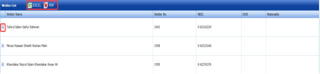
If you click (Expand Icon) of the respective welder, the All WPQ box shows the details of all WPQs of the welder, and the Assigned to Project box shows any WPQ that has been assigned to a project.
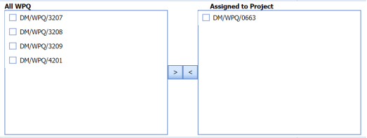
-
If you want to assign any WPQ for the project, select the respective WPQ in the All WPQ box, and then click

(Assign WPQ button).
The selected welder will be assigned to the project.
-
If you want to reject any WPQ that has been assigned for the project, select the respective WPQ in the Assigned to Project box, and then click
 (Reject WPQ button).


3.13.7 WPQ Details
The WPQ details field in the welders in projects page shows the WPQ details of each welder including welder’s name, welder number, welding process name, weld metal thickness, position, and so on.
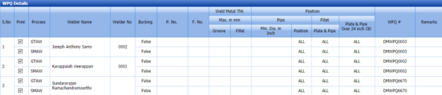
If you want to take a print of any WPQ details, click the checkbox provided in the Print Column.
3.14 Inspectors in Projects
The Inspectors in Projects tab in the Project Data menu helps you to map inspectors for the specific project.
-
Click the Inspectors in Projects tab.
The Project Mapping – Inspectors page opens
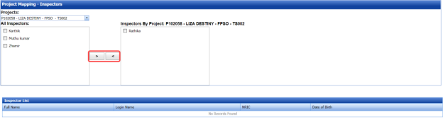
Figure 3.14: Project Mapping – Inspectors page
The Project Mapping – Inspectors page shows a list of inspectors, which is added in the Master Data. If you want to map any inspectors for a specific project, do the following,
- Select a project you want from the Projects box.
A list of available inspectors will be displayed.
-
Select the check box of the respective inspector which you want to map for the selected project.
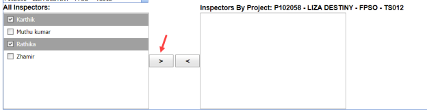
-
Click
 (Map icon).
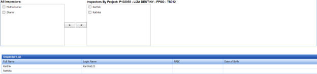
The selected inspectors are mapped for the selected project.

The Inspector List window shows the inspector’s name, login name, NRIC, and Date of birth.


3.15 WPQ Search
The WPQ Search tab in the Project Data menu used to filter the specific WPQ result. To perform the WPQ search,
- Click WPQ Search in the Project Data menu.
The WPQ Search page opens with the WPQ Results window.

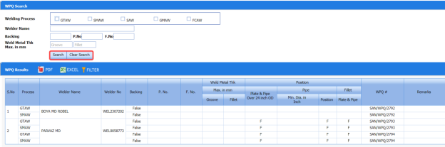
Figure 3.15: WPQ Search page
- In the Welding Process box, select a welding process from the given welding processes.
- In the Welder Name box, enter the name of a welder.
- In the Backing box, enter the backing details.
-
In the Weld Metal Thk Max. in mm box, enter the minimum and maximum thickness of the weld metal.
-
Click
 (Search button).
The WPQ Results window shows the WPQ details based on the given data.

3.15.1 Export WPQ Results
You can export the WPQ results in the WPQ Results window in both the pdf and excel formats by using  (PDF button) and
  (Excel button). To know how to export, see the topic, “Export P&ID list”.
3.15.2 Filter WPQ Results
If you want to filter any WPQ in the WPQ Results page, you can use  (FILTER button) provided on the WPQ Results page. To know how to filter, see the topic, “Filter P&ID”.
3.16 Bill of Material
Bill of Material is a comprehensive inventory of the raw materials, assembles, sub assembles, parts and components, as well as the quantity of each, needed to the piping fabrication.
The Bill of Material tab in the Project Data menu used to add a new bill of material.
-
Click Bill of Material in the Project Data menu.
The Bill of Material page opens.
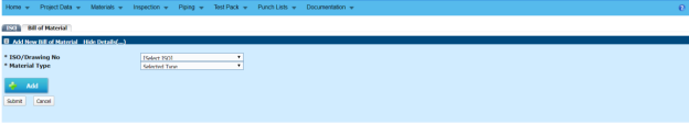
Figure 3.16: Bill of Material page

3.16.1 Add a Bill of Material
If you want to add a bill of material,
- In the ISO/Drawing No box, select the ISO drawing number from a drop-down list.
- In the Material Type box, select a material type from a drop-down list.
-
Click
 (Add button).
A new window opens to add the material details.
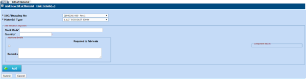
- In the Stock Code box, enter the stock code.
- In the Quantity box, enter the quantity of the material.
- In the Component Details box, enter the component details.
- In the Remarks box, enter your remarks if any.
- If the materials are need to be fabricated, enable the checkbox of the Required to fabricate option.
- Click Submit.
The bill of material is added.


3.17 Spools Location – Masters
The Spools Location – Masters tab in the Project Data menu used to add the details of the spool location.
- Click Spools Location – Masters in the Project Data menu.
The Spools Location page opens.

Figure 3.17: Spools Location page
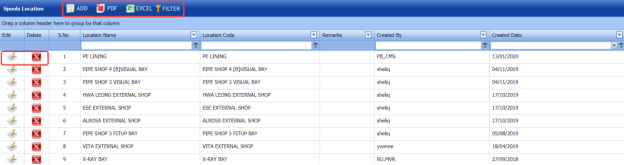
3.17.1 Add a Spool Location
If you want to add a spool location, do the following steps,
-
Click
 (ADD button) in the Spools Location page. See Fig 3.17.
A new window opens to add a new spool location.
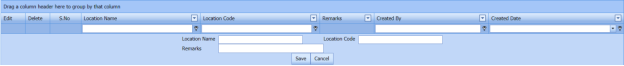
- In the Location Name box, enter the location name.
- In the Location Code box, enter the location code.
- In the Remarks box, enter your remarks if any.
- Click Save.
The spool location is successfully added.


3.17.2 Edit a Spool Location
If you want to edit any existing spool location detail in the Spools Location page,
-
Click
 (Edit icon)of the respective spool location. See Fig 3.17.
The Spools Location page shows the details of the selected location.
- Edit the details where you want.
- Click Save.

3.17.3 Delete a Spool Location
If you want to delete any existing spool location in the Spools Location page, you can use  (Delete icon). To know how to delete, see the topic, “Delete P&ID”.
3.17.4 Export Spool Location List
You can export a list of spool location added in the Spools Location page in both the pdf and excel formats by using  (PDF button) and
  (Excel button). To know how to export, see the topic, “Export P&ID list”.
3.17.5 Filter a Spool Location
If you want to filter any spool location in the Spools Location page, you can use  (FILTER button) provided on the Spools Location page. To know how to filter, see the topic, “Filter P&ID”.
3.18 Workflow Settings
The Workflow Settings tab in the Project Data menu used to set a workflow in the Piping project.
-
Click Workflow Settings in the Project Data menu.
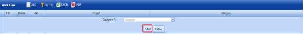
The Workflow page opens.

Figure 3.18: Workflow page
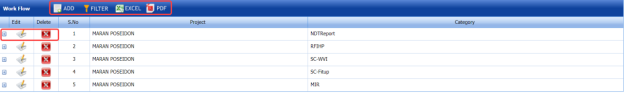
3.18.1 Add a Workflow
If you want to add a workflow,
-
Click
 (ADD button) in the Workflow See Fig 3.18.
The page shows a new window to add the category.
-
In the Category box, select a category from a drop-down list.
- Click Save.
The added category will be listed in the Workflow page. See Fig 3.18.
-
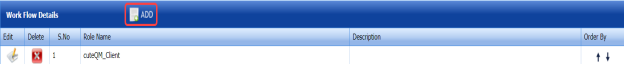
Click
 (Add icon) of the respective category.
The Workflow Details window opens.
-
Click
 (ADD button) in the Workflow Details window.
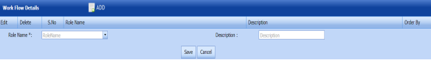
- In the Role Name box, select a role name from a drop-down list.
- In the Description box, enter the description for the role name.
- Click Save.


3.18.2 Edit a Workflow
If you want to edit any existing workflow in the Workflow page,
-
Click
 (Edit icon) of the respective workflow. See Fig 3.18.
The Workflow page shows the details of the selected workflow.
- Edit the details where you want.
- Click Save.

3.18.3 Delete a Workflow
If you want to delete any existing workflow in the Workflow page, you can use  (Delete icon) provided in the Workflow page. To know how to delete, see the topic, “Delete P&ID”.
3.18.4 Export Workflow List
You can export a list of workflows added in the Workflow page in both the pdf and excel formats by using  (PDF button) and (Excel button). To know how to export, see the topic, “Export P&ID list”.
3.18.5 Filter a Workflow
If you want to filter any specific workflow, you can use  (FILTER button) located on the Workflow page. To know how to filter, see the topic, “Filter P&ID”.
3.19 Inspection Requirements
The Inspection Requirements tab in the Project Data menu used to add the requirement details for the inspection.
- Click Inspection Requirements in the Project Data menu.
The Inspection Requirements page opens.
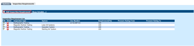
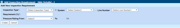
Figure 3.19: Inspection Requirements page

3.19.1 Add an Inspection Requirement
If you want to add an inspection requirement, do the following steps,
-
Click Add Inspection Requirement.
The Add New Inspection Requirement window opens.

-
In the Inspection Type box, select an inspection type.
- If you want to add the system detail, select the System option and choose a system from a drop-down list.
- If you want to add the line number detail, select the Line Number option and choose a line number from a drop-down list.
- In the Requirement box, enter the inspection requirement percentage.
- In the Pressure Rating From and To box, enter the pressure rating range.
- Click Create.
The inspection requirement details will be added and listed in the Inspection Requirements page.
3.19.2 Edit an Inspection Requirement
If you want to edit any added inspection requirement details,
-
Click
 (Edit icon) of the respective inspection requirement. See Fig 3.19.
The added inspection requirement details open.
- Edit the details where you want.
-
Click Save.

3.19.3 Delete an Inspection Requirement
If you want to delete any existing inspection requirement, you can use  (Delete icon). To know how to delete, see the topic, “Delete P&ID”.
3.20 Template Check Sheets
The Template Check Sheets tab in the Project Data menu helps you to add MC/SC – Check Record (CR)/Check Sheet (CS) templates. To navigate to the templates adding page,
- Click Template Check Sheets in the Project Data menu.
The MC/SC – CR/CS Templates page opens.

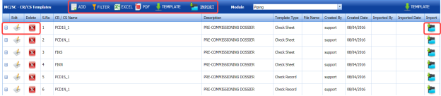
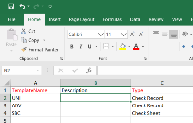
Figure 3.20: MC/SC – CR/CS Templates page
3.20.1 Add a CR/CS Template
If you want to add a CR/CS template,
-
Click
 (ADD button) in the MC/SC – CR/CS Templates page. See Fig 3.20.
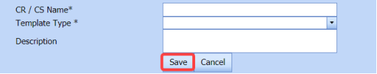
The page opens a new window to add the details of a template.
 Note: The field notified with a symbol (*) is mandatory. You must enter the relevant details in that fields before saving.
 - In the CR/CS Name box, enter the name for CR/CS.
- In the Template Type box, select a template whether CR or CS.
- In the Description box, enter the description for CR/CS.
- Click Save.
The template is successfully added and listed in the MC/SC – CR/CS Templates page. Once you have added the template details, you must import the respective template.


3.20.2 Import a CR/CS Template
If you want to import CR/CS template,
-
Click
 (Add icon) of the respective CR/CS name in the MC/SC – CR/CS Templates page.
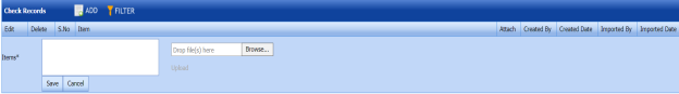
The Check Records window opens.
-
Click
 (ADD button) in the Check Records
- In Items box, enter the details of items.
- Browse and attach a CS/CR template you want to import.
- Click Save.


3.20.3 Edit a CR/CS Template
If you want to edit any added CR/CS template in the MC/SC – CR/CS Templates page,
-
Click
 (Edit icon) of the respective CR/CS template. See Fig 3.20
The MC/SC – CR/CS Templates page shows the details of the selected CR/CS template.
-
Edit the details where you want.
-
Click Save.

3.20.4 Delete a CR/CS Template
If you want to delete any existing CR/CS template in the MC/SC – CR/CS Templates page, you can use  (Delete icon) provided in the MC/SC – CR/CS Templates page. To know how to delete, see the topic, “Delete P&ID”.
3.20.5 Export CR/CS Template list
You can export a list of CR/CS templates added in the MC/SC – CR/CS Templates page in both the pdf and excel formats by using  (PDF button) and
  (Excel button). To know how to export, see the topic, “Export P&ID list”.
3.20.6 Filter a CR/CS Template
If you want to filter any specific CR/CS template in the MC/SC – CR/CS Templates page, you can use  (FILTER button) located on the MC/SC – CR/CS Templates page. To know how to filter, see the topic, “Filter P&ID”.
3.20.7 Import Multiple CR/CS Templates
If you want to import multiple CR/CS templates together, do the following,
-
Click
 (TEMPLATE button). See Fig 3.20.
An excel worksheet will be downloaded with a predefined template to enter the details of CR/CS templates.

- Enter the required CR/CS template details in the respective columns of the excel worksheet.
-
Once you have added the CR/CS template details in the excel worksheet, save the excel worksheet on your computer.
-
Click
 (IMPORT button). See Fig 3.20.
A new window opens for importing the excel worksheet saved on your computer.

-
Click
 (Browse button) to select the excel worksheet to be uploaded.
 -
Select the excel worksheet you want to upload from your computer.
-
Click
 (Upload button) to export the CR/CS template details that are included in the excel worksheet.


The details of the CR/CS templates in the worksheet will be displayed in the MC/SC – CR/CS Templates page.
3.21 Certificate Template Check Sheets
The Certificate Template Check Sheets tab in the Project Data menu used to add the details included in a certificate.
-
Click Certificate Template Check Sheets in the Project Data.
The Certificates page opens.

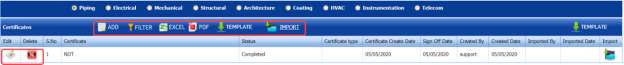
Figure 3.21: Certificates page
3.21.1 Add a Certificate
If you want to add a certificate,
-
Click
 (ADD button) in the Certificates See Fig 3.21.
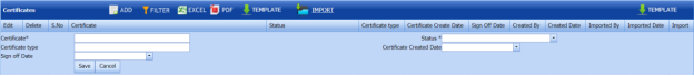
The page opens a new window to add the details of a certificate.
 Note: The field notified with a symbol (*) is mandatory. You must enter the relevant details in that fields before saving.
 - In the Certificate box, enter the name of the certificate.
- In the Status box, select the status of the certificate.
- In the Certificate Type box, enter the description for CR/CS.
- In the Certificate Created Date box, select the created date of the certificate.
- In the Sign off Date box, select the sign off date of the certificate.
- Click Save.


The certificate is successfully added and listed in the Certificates page. Once you have added the certificate details, you must import the respective certificate.
3.21.2 Import a Certificate
If you want to import a copy of the certificate,
-
Click
 (Import icon) of the respective certificate in the Certificates page.
 -
Attach the copy of the certificate.

3.21.3 Edit a Certificate
If you want to edit any added certificate in the Certificates page,
-
Click
 (Edit icon) of the respective certificate. See Fig 3.21.
The Certificates page shows the details of the selected certificate.
- Edit the details where you want.
-
Click Save.

3.21.4 Delete a Certificate
If you want to delete any existing certificate in the Certificates page, you can use  (Delete icon) provided in the Certificates page. To know how to delete, see the topic, “Delete P&ID”.
3.21.5 Export Certificate list
You can export a list of certificates added in the Certificates page in both the pdf and excel formats by using  (PDF button) and
  (Excel button). To know how to export, see the topic, “Export P&ID list”.
3.21.6 Filter a Certificate
If you want to filter any specific certificate in the Certificates page, you can use  (FILTER button) located on the Certificates page. To know how to filter, see the topic, “Filter P&ID”.
3.21.7 Import Multiple Certificates
If you want to import multiple certificates together, do the following,
-
Click
 (TEMPLATE button). See Fig 3.21.
An excel worksheet will be downloaded with a predefined template to enter the details of certificates.
- Enter the required certificate details in the respective columns of the excel worksheet.
-
Once you have added the certificate details in the excel worksheet, save the excel worksheet on your computer.
-
Click
 (IMPORT button). See Fig 3.21.
A new window opens for importing the excel worksheet saved on your computer.

-
Click
 (Browse button) to select the excel worksheet to be uploaded.
 - Select the excel worksheet you want to upload from your computer.
-
Click
 (Upload button) to export the certificate details that are included in the excel worksheet.


The details of the certificates in the worksheet will be displayed in the Certificates page.
3.22 Welder Qualification Test Coupon
The Welder Qualification Test Coupon tab in the Project Data menu used to add the welder qualification test coupon details.
If you want to add a welder qualification test coupon, do the following steps,
-
Click Welder Qualification Test Coupon in the Project Data menu.
The Welder Qualification Test Coupon page opens.

Figure 3.22: Welder Qualification Test Coupon page

3.22.1 Add a Welder Qualification Test Coupon
If you want to add a welder qualification test coupon report,
-
Click
 (ADD button) in the Welder Qualification Test Coupon page. See Fig 3.22.
A new window opens to add the welder qualification test coupon.

 Tip: A report number for a new welder qualification test coupon will be updated automatically in the Report Number box.
 - In the Test Date box, select the welder qualification test date.
- In the Work Order box, enter the work order name.
-
Click Save.


The welder qualification test coupon will be added and listed in the Welder Qualification Test Coupon.
3.22.2 Add Welder Qualification Test Coupon Details
To add the welder qualification test coupon details,
-
Click
 (Add icon) of the respective test coupon. See Fig 3.22.
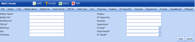
The WQTC Details window opens.

-
Click
 (ADD button) in the WQTC Details window.
A new window opens to enter the WQTC details.
-
In the Welder Name box, enter the welder name.
-
In the Position box, enter the position detail.
- In the Welder No box, enter the welder number.
- In the RT Report No box, enter the RT report number.
- In the Work Permit box, enter the work permit detail.
- In the Remarks box, enter your remarks if any.
- In the FIN No box, enter the FIN number.
- In the Department box, enter the department name.
- In the Weld Type box, enter the welding type.
- In the Process box, select the welding process.
- In the Size box, enter the welding size.
- In the Visual Result box, select the visual result.
- In the Thickness box, enter the thickness of the welding.
-
In the RT Result box, select the RT result.
- Click Save.


3.22.3 View a Welder Qualification Test Coupon Report
To view a welder qualification test coupon report, click (Print icon) of the respective test coupon, which is provided in the Report column of the Welder Qualification Test Coupon page.
3.22.4 Approve a Welder Qualification Test Coupon
Once you have added the welder qualification test coupon details, you must approve the test coupon. To approve the test coupon,
-
Click
 (Submit icon) in the Action column.

3.33.5 Export Welder Qualification Test Coupon List
You can export a list of test coupons added in the Welder Qualification Test Coupon page in both the pdf and excel formats by using  (PDF button) and
  (Excel button). To know how to export, see the topic, “Export P&ID list”.
3.33.6 Filter a Welder Qualification Test Coupon
If you want to filter any specific test coupon in the Welder Qualification Test Coupon page, you can use  (FILTER button) located on the page. To know how to filter, see the topic, “Filter P&ID”.
3.23 Valve List
The Valve List tab in the Project Data menu helps you add the valve details.
-
Click Valve List in the Project Data menu.
The Valve List page opens.
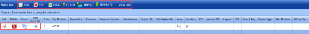
Figure 3.23: Valve List page

3.23.1 Add a Valve
If you want to add a new valve, do the following steps,
-
Click
 (ADD button) in the Valve List page. See Fig 3.23.
A new window opens to add a new valve.
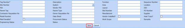
 Note: The fields notified with a symbol (*) are mandatory. You must enter the relevant details in that fields before saving.
 - In the Tag Number box, select the tag number of the valve.
- In the Description box, enter the description for the valve.
- In the Function box, enter the function name.
- In the Sequence Number box, enter the sequence number of the valve.
- In the Site Number box, enter the site number.
- In the System box, select a system.
- In the Area box, enter the area name.
- In the Location box, enter the location name.
- In the PID box, enter the PID number.
- In the Vendor PID box, enter the vendor PID number.
- In the Layout box, enter the layout detail.
- In the Parent tag box, enter the parent tag number.
- In the Parent type box, enter the parent type.
- In the Skid Number box, enter the skid number.
- In the PO Number box, enter the PO number.
- In the Manufacturer box, enter the manufacturer name.
- In the Supplier box, enter the supplier name.
- In the Model Number box, enter the model number of the valve.
- In the Data Sheet box, enter the data sheet detail.
- In the Procurement Status box, enter the procurement status detail.
- In the Remarks box, enter your remarks if any.
- Click Save.
The valve is successfully added.


3.23.2 Clone a Valve
The Clone option provided in the Valve List page used to add a new valve from previously added valve. If a valve to be added is having the same specifications of any valve already listed in the Valve List page, you can add the new valve by using  (Clone icon).
-
In the Valve List page, find out the valve you want to clone.
-
Click
 (Clone icon) of the respective valve.
 The Valve List page shows the details of selected valve. See the below figure.

- If you want to change any details, you can change in the respective boxes.
- Click Save.
The new valve is successfully added and listed in the Valve List page.

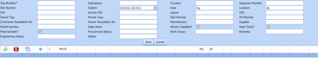
3.23.3 Edit a Valve
If you want to edit any existing valve in the Valve List page,
-
Click
 (Edit icon) of the respective valve. See Fig 3.23.
The Valve List page shows the details of the selected valve.
- Edit the details where you want.
- Click Save.

3.23.4 Delete a Valve
If you want to delete any existing valve in the Valve List page, you can use  (Delete icon) provided in the Valve List page. To know how to delete, see the topic, “Delete P&ID”.
3.23.5 Export Valve List
You can export a list of valves added in the Valve List page in both the pdf and excel formats by using  (PDF button) and
  (Excel button). To know how to export, see the topic, “Export P&ID list”.
3.23.6 Filter a Valve
If you want to filter any valve in the Valve List page, you can use  (FILTER button) provided on the Valve List page. To know how to filter, see the topic, “Filter P&ID”.
3.23.7 Import Multiple Valves
If you want to import multiple valves together, do the following,
-
Click
 (TEMPLATE button). See Fig 3.23.
An excel worksheet will be downloaded with a predefined template to enter the details of joints.
- Enter the required valve details in the respective columns of the excel worksheet.
-
Once you have added the valve details in the excel worksheet, save the excel worksheet on your computer.
-
Click
 (IMPORT button). See Fig 3.23.
A new window opens for importing the excel worksheet saved on your computer.

-
Click
 (Browse button) to select the excel worksheet to be uploaded.
 -
Select the excel worksheet you want to upload from your computer.
-
Click
 (Upload button)to export the valve details that are added in the excel worksheet.


The details of the valves in the worksheet will be displayed in the Valve List page.
3.24 Special Component
The Special Component tab in the Project Data menu used to add any special component to be used in the Piping project.
To add the details of special component, follow the same procedure given in the topic, “Valve List”.
No Comments