
Inspection – Quality
10.0 Inspection – Quality
The Inspection - Quality menu in the app used to add the NDT inspection details for the added NDT requests.
|
Users assigned with cuteQM_QAQC role only can view and access the Inspection - Quality menu and their functionalities. |
10.1 Fit up Report
Once you have added the Fit up inspection request, the added request will be moved here to update the fit up inspection details. Fit up inspection will be carried out by the person who has assigned with the inspection role.
To add the fit up inspection details, do the following steps,
1. Click Fit up Report in the Inspection – Quality
The Fit up Inspection page opens.
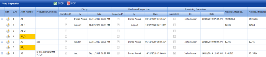
Figure 10.1: Fit up Inspection page
10.1.1 Add Mechanical Inspection Details
|
Users assigned with cuteQM_MechInspection role only can view the Mechanical Inspection window and add the mechanical inspection details. |
1. Click  (Edit icon) of the respective joint for which you want to add the mechanical inspection details.
The Mechanical Inspection window opens with the added Fit up details.
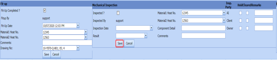
 Note: You cannot edit the data in the Fit up window.
2. If the mechanical inspection is completed, select the checkbox of the Inspected option in the Mechanical Inspection window.
3. In the Inspection Date box, select the mechanical inspection date.
4. In the Result box, select the result of the mechanical inspection.
5. In the Material 1 Heat No box, select the heat number of the first material.
6. In the Material 2 Heat No box, select the heat number of the second material.
7. In the Comments box, enter your comments if any.
8. In the Insp. Party field, if the AI, Client or Owner hold or Clear the inspection, select the respective checkbox.
9. Click Save.
The mechanical inspection details will be added successfully. Once the mechanical inspection is completed, the Pre-welding inspection details needs to be added.
10.1.2 Add Pre-welding Inspection Details
|
Users assigned with cuteQM_WeldInspection role only can view the Pre-Welding Inspection window to add the pre-welding inspection details. |
1. Click (Edit icon) of the respective joint for which you want to add the pre-welding inspection details.
The Pre-welding Inspection window opens with the added Fit up and mechanical inspection details.

Note: You cannot edit the data in the Fit up and Mechanical Inspection windows.
2. If the pre-welding inspection is completed, select the checkbox of the Inspected option in the Pre-welding Inspection window.
3. In the Inspection Date box, select the inspection date.
4. In the Result box, select the result of the pre-welding inspection.
5. In the Comments box, enter your comments if any.
6. Click Save.
The pre-welding inspection details are updated successfully. Once the pre-welding inspection has completed for the joint, the respective joint will be moved for the weld visual inspection.
10.1.3 Add Mechanical RFI Data for Any Fit up Inspection Report
If you want to add mechanical RFI data for any fit up inspection report,
1. Click  (Add icon) in the Mech RFI Data column of the Fit up Inspection
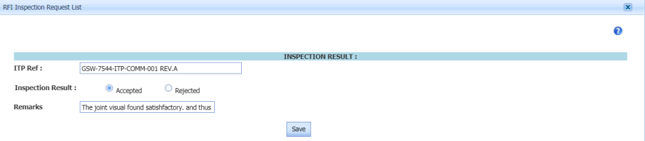
The RFI Inspection Request List window opens.
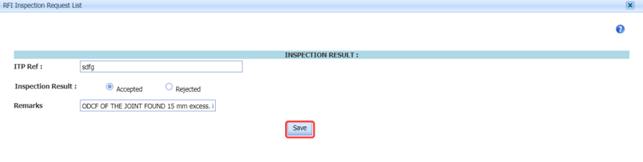
2. In the ITP Ref box, enter the ITP reference detail.
3. In the Inspection Result field, select the inspection result whether Accepted or Rejected.
4. In the Remarks box, enter your remarks if any.
5. Click Save.
10.1.4 Add RFI Data for Any Fit up Inspection Report
If you want to add RFI data for any fit up inspection report,
1. Click (Add icon) in the RFI Data column of the Fit up Inspection
The RFI Inspection Request List window opens.

2. In the ITP Ref box, enter the ITP reference detail.
3. In the Inspection Result field, select the inspection result whether Accepted or Rejected.
4. In the Remarks box, enter your remarks if any.
5. Click Save.
10.1.5 Add Dimensional Inspection Result Details
If you want to add the dimensional inspection result details for any joint,
1. Click (Add icon) in the Report Details column of the Fit up Inspection
The Dimensional Details window opens.
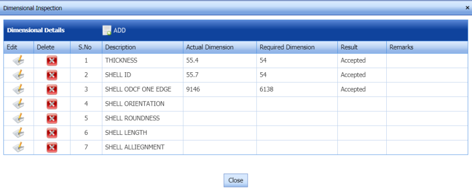
2. Click  (ADD button) in the Dimensional Details
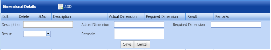
3. In the Description box, enter the description for the dimensional inspection.
4. In the Actual Dimension box, enter the actual dimension value.
5. In the Required Dimension box, enter the required dimension value.
6. In the Result box, select the result of dimensional inspection.
7. In the Remarks box, enter your remarks if any.
8. Click Save.
10.1.6 View a Mechanical RFI Report
If you want to view the mechanical RFI report, click  (Print icon) provided in the Mech RFI Report column.
10.1.7 View an RFI Report for Any Fit up Inspection Report
If you want to view the RFI report for any request, click (Print icon) provided in the RFI Report column.
10.1.8 View a Mechanical Inspection Report
If you want to view the mechanical inspection report for any request, click (Print icon) provided in the Mech Report column.
10.1.9 View a Fit up Inspection Report
If you want to view the fit up inspection report for any request, click (Print icon) provided in the Report column.
10.1.10 Attach a File into a Fit up Inspection report
If you want to attach a file with any fit up inspection report in the Fit up Inspection page, you can use  (Attach icon) provided in the Attachment column for the respective joint. To know how to attach, see the topic, “Attach a file into a PQR”.
10.1.11 Export Fit up Inspection List
You can export a list of fit up inspection in the Fit up Inspection page in the pdf and excel formats by using  (PDF button)
  (Excel button). To know how to export, see the topic, “Export Clients List”.
10.2 Weld Visual Report
Once you have added the weld visual inspection request, the added request will be moved here to update the weld visual inspection details. Weld visual inspection will be carried out by the person who has assigned with the inspection role.
To add the weld visual inspection details, do the following steps,
1. Click Weld Visual Report in the Inspection – Quality
The Weld Visual Inspection page opens.
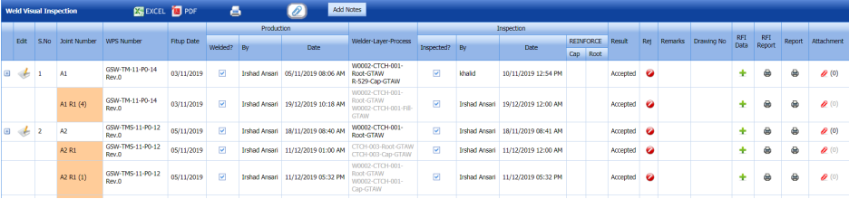
Figure 10.2: Weld Visual Inspection page
10.2.1 Add Weld Visual Inspection Details
|
Users assigned with cuteQM_QAQC role only can view the Inspection window and add the weld visual inspection details. |
1. Click  (Edit icon) of the respective joint for which you want to add the weld visual inspection details.
The Inspection window opens with the added production details.
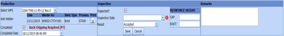
 Note: You cannot edit the data in the Production window.
2. If the weld visual inspection is completed, select the checkbox of the Inspected option in the Inspection window.
3. In the Inspection Date box, select the weld visual inspection date.
4. In the Result box, select the result of the weld visual inspection.
5. In the Reinforce Height field, enter the Cap and Root detail.
6. In the Remarks box, enter your remarks if any.
7. Click Save.
The weld visual inspection details will be added successfully.
10.2.2 Add RFI Data for Any Weld Visual Inspection Report
If you want to add RFI data for any weld visual inspection report,
1. Click (Add icon) in the RFI Data column of the Weld Visual Inspection
The RFI Inspection Request List window opens.
2. In the ITP Ref box, enter the ITP reference detail.
3. In the Inspection Result field, select the inspection result whether Accepted or Rejected.
4. In the Remarks box, enter your remarks if any.
5. Click Save.
10.2.3 View an RFI Report for Any Weld Visual Inspection Report
If you want to view the RFI report for any weld visual inspection report, click  (Print icon) provided in the RFI Report column.
10.2.4 View a Weld Visual Inspection Report
If you want to view the weld visual inspection report, click (Print icon) provided in the Report column.
10.2.5 Attach a File into a Weld Visual Inspection report
If you want to attach a file with any weld visual inspection report in the Weld Visual Inspection page, you can use ![]() (Attach icon) provided in the Attachment column for the respective joint. To know how to attach, see the topic, “Attach a file into a PQR”.
(Attach icon) provided in the Attachment column for the respective joint. To know how to attach, see the topic, “Attach a file into a PQR”.
10.2.6 Export Weld Visual Inspection List
You can export a list of weld visual inspection in the Weld Visual Inspection page in the pdf and excel formats by using  (PDF button)
  (Excel button). To know how to export, see the topic, “Export Clients List”.
10.3 Final Dimensional Report
The Final Dimensional Report tab in the Inspection – Quality menu used to add the final dimensional inspection result for added request.
1. Click Final Dimensional Report in the Inspection – Quality
The Final Dimensional Report page opens.
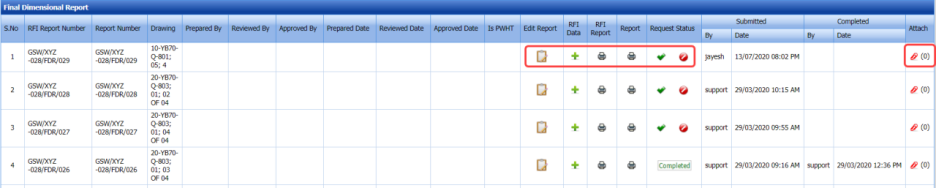
Figure 10.3: Final Dimensional Report page
The page shows a list of added final dimensional requests.
10.3.1 Add Final Dimension Report Details
If you want to add the final dimension report details,
1. Click  (Edit icon) in the Edit Report column for the respective request.
The Final Dimension Report window opens.
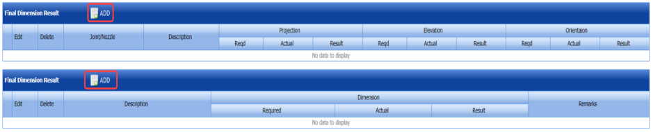
2. Click  (ADD button) in the Final Dimension Report
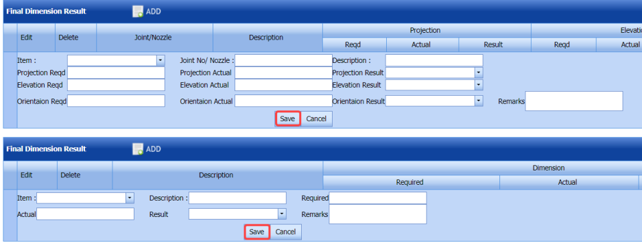
3. In the Item box, select an item from a drop-down list.
4. In the Joint No/Nozzle box, enter the joint number or nozzle number.
5. In the Description box, enter the description for the request.
6. In the Projection Reqd box, enter the required projection value.
7. In the Projection Actual box, enter the actual projection value.
8. In the Projection Result box, select the projection result.
9. In the Elevation Reqd box, enter the required elevation value.
10. In the Elevation Actual box, enter the actual elevation value.
11. In the Elevation Result box, select the elevation result.
12. In the Orientation Reqd box, enter the required orientation value.
13. In the Orientation Actual box, enter the actual orientation value.
14. In the Orientation Result box, select the orientation result.
15. In the Item box, select an item from a drop-down list.
16. In the Required box, enter the required dimension.
17. In the Actual box, enter the actual dimension.
18. In the Result box, select the result of final dimension inspection.
19. In the Remarks box, enter your remarks if any.
20. Click Save.
10.3.2 Add Final Dimension Inspection Result Details
If you want to add the final dimension inspection result details,
1. Click (Add icon) in the RFI Data column for the respective request.
The RFI Inspection Request List window opens.

2. In the ITP Ref box, enter the ITP reference detail.
3. In the Inspection Result field, select the inspection result.
4. In the Remarks box, enter your remarks if any.
5. Click Save.
10.3.3 Submit Final Dimension Inspection Result
Once you have added the final dimension inspection result, the Request Status column in the Final Dimensional Report page is appeared with (Submit and Reject icons). See Fig 10.3.
1. If you want to submit the final dimension inspection result, click  (Submit icon) in the Request Status Otherwise click
  (Reject icon) to reject the request.
Once the final dimension inspection result is updated, the completed status will be updated in the Completed column.
10.3.4 View an RFI Report for Final Dimension Inspection
If you want to view the RFI report for any final dimension inspection, click  (Print icon) provided in the RFI Report column.
10.3.5 View a Final Dimension Inspection Report
If you want to view the final dimension inspection report, click (Print icon) provided in the Report column.
10.3.6 Attach a file into a Final Dimension Inspection Report
If you want to attach a file with any final dimension inspection report in the Final Dimension Report page, you can use (Attach icon) provided in the Attachment column for the respective report. To know how to attach, see the topic, “Attach a file into a PQR”.
10.4 Nozzle Marking Report
The Nozzle Marking Report tab in the Inspection – Quality menu used to add the nozzle marking inspection result for added request.
1. Click Nozzle Marking Report in the Inspection – Quality
The Nozzle Marking Inspection page opens.

Figure 10.4: Nozzle Marking Inspection page
The page shows a list of added nozzle marking inspection requests.
10.4.1 Add Nozzle Marking Report Details
1. Click (Edit icon) in the Edit Report column for the respective request.
The Nozzle Marking Result and Report Photos windows open.
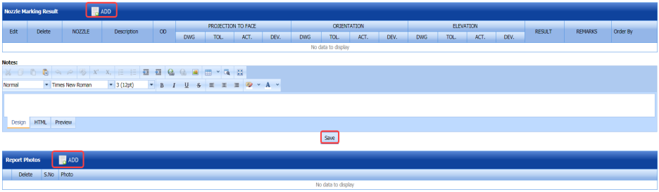
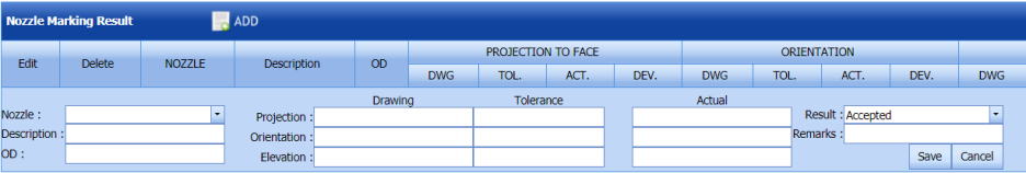
3. In the Nozzle box, select a nozzle from a drop-down list.
4. In the Description box, enter the description for the request.
5. Enter the projection, orientation, and elevation value.
6. In the Result box, select the result.
7. In the Remarks box, enter your remarks if any.
8. Click Save.
9. In the Report Photos window, click  (ADD button) and attach a photo.
10.4.2 Add Nozzle Marking Inspection Result Details
If you want to add the nozzle marking inspection result details,
1. Click  (Add icon) in the RFI Data column for the respective request.
The RFI Inspection Request List window opens.

2. In the ITP Ref box, enter the ITP reference detail.
3. In the Inspection Result field, select the inspection result.
4. In the Remarks box, enter your remarks if any.
5. Click Save.
10.4.3 Submit Nozzle Marking Inspection Result
Once you have added the nozzle marking inspection result, the Request Status column in the Nozzle Marking Inspection page is appeared with (Submit and Reject icons). See Fig 10.4.
1. If you want to submit the nozzle marking inspection result, click  (Submit icon) in the Request Status Otherwise click
  (Reject icon) to reject the request.
Once the nozzle marking inspection result is updated, the completed status will be updated in the Completed column.
10.4.4 View an RFI Report for Nozzle Marking Inspection
If you want to view the RFI report for any nozzle marking inspection, click  (Print icon) provided in the RFI Report column.
10.4.5 View a Nozzle Marking Inspection Report
If you want to view the nozzle marking inspection report, click (Print icon) provided in the Report column.
10.4.6 Attach a file into a Nozzle Marking Inspection Report
If you want to attach a file with any nozzle marking inspection report in the Nozzle Marking Inspection page, you can use (Attach icon) provided in the Attachment column for the respective report. To know how to attach, see the topic, “Attach a file into a PQR”.
10.5 Alignment Reading Report
The Alignment Reading Report tab in the Inspection – Quality menu used to add the alignment reading inspection result for added request.
1. Click Alignment Reading Report in the Inspection – Quality
The Alignment Reading Inspection page opens.
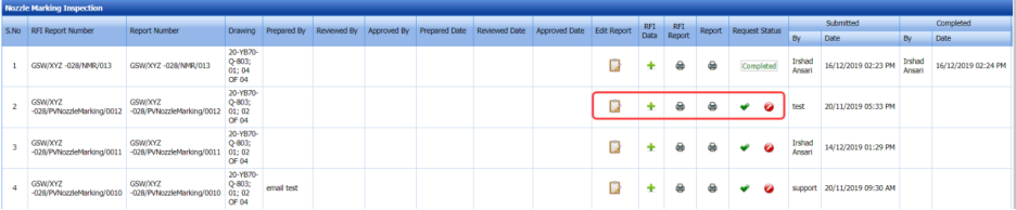
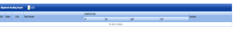
Figure 10.5: Alignment Reading Inspection page
The page shows a list of added alignment reading inspection requests.
10.5.1 Add Alignment Reading Report Details
If you want to add the alignment reading report details,
1. Click  (Edit icon) in the Edit Report column for the respective request.
The Alignment Reading Report window opens.
1. Click (ADD button) in the Alignment Reading Report
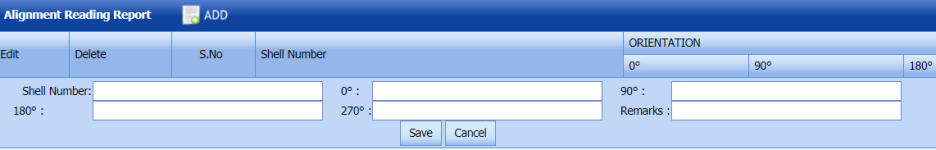
2. In the Shell Number box, enter the shell number.
3. Enter the orientation level in 0, 90,180 and 270 degrees.
4. In the Remarks box, enter your remarks if any.
5. Click Save.
10.5.2 Add Alignment Reading Inspection Result Details
If you want to add the alignment reading inspection result details,
1. Click (Add icon) in the RFI Data column for the respective request.
The RFI Inspection Request List window opens.

2. In the ITP Ref box, enter the ITP reference detail.
3. In the Inspection Result field, select the inspection result.
4. In the Remarks box, enter your remarks if any.
5. Click Save.
10.5.3 Submit Alignment Reading Inspection Result
Once you have added the alignment reading inspection result, the Request Status column in the Alignment Reading Report page is appeared with (Submit and Reject icons). See Fig 10.5.
1. If you want to submit the alignment reading inspection result, click (Submit icon) in the Request Status Otherwise click (Reject icon) to reject the request.
Once the alignment reading inspection result is updated, the completed status will be updated in the Completed column.
10.5.4 View an RFI Report for Alignment Reading Inspection
If you want to view the RFI report for any alignment reading inspection, click (Print icon) provided in the RFI Report column.
10.5.5 View an Alignment Reading Inspection Report
If you want to view the alignment reading inspection report, click (Print icon) provided in the Report column.
10.5.6 Attach a file into an Alignment Reading Inspection Report
If you want to attach a file with any alignment reading inspection report in the Alignment Reading Report page, you can use (Attach icon) provided in the Attachment column for the respective report. To know how to attach, see the topic, “Attach a file into a PQR”.
10.6 Ovality Reading Report
The Ovality Reading Report tab in the Inspection – Quality menu used to add the ovality reading inspection result for added request.
1. Click Ovality Reading Report in the Inspection – Quality
The Ovality Reading Report page opens.
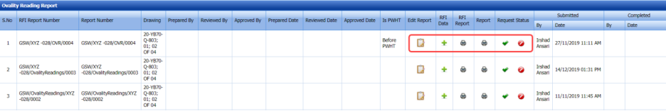
Figure 10.6: Ovality Reading Report page
The page shows a list of added ovality reading inspection requests.
10.6.1 Add Ovality Reading Report Details
If you want to add the ovality reading report details,
1. Click (Edit icon) in the Edit Report column for the respective request.
The Ovality Reading Details window and the Ovality Reading Report window opens.
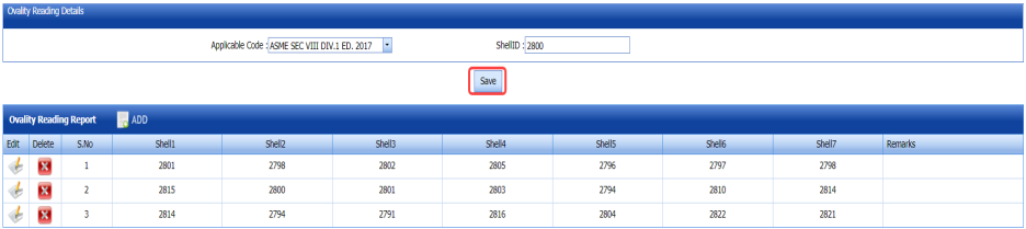
2. In the Applicable Code box, select the applicable code.
3. In the Shell ID box, enter the shell id.
4. Click Save.
5. Click (ADD button) in the Ovality Reading Report
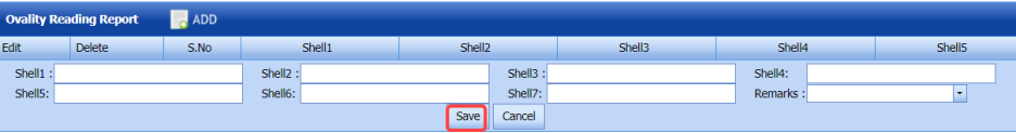
6. In the Shell1 to Shell7 boxes, enter the shell numbers.
7. In the Remarks box, enter your remarks if any.
8. Click Save.
10.6.2 Add Ovality Reading Inspection Result Details
If you want to add the ovality reading inspection result details,
1. Click (Add icon) in the RFI Data column for the respective request.
The RFI Inspection Request List window opens.

2. In the ITP Ref box, enter the ITP reference detail.
3. In the Inspection Result field, select the inspection result.
4. In the Remarks box, enter your remarks if any.
5. Click Save.
10.6.3 Submit Ovality Reading Inspection Result
Once you have added the ovality reading inspection result, the Request Status column in the Ovality Reading Report page is appeared with (Submit and Reject icons). See Fig 10.6.
1. If you want to submit the ovality reading inspection result, click (Submit icon) in the Request Status Otherwise click (Reject icon) to reject the request.
Once the ovality reading inspection is updated, the completed status will be updated in the Completed column.
10.6.4 View an RFI Report for Ovality Reading Inspection
If you want to view the RFI report for any ovality reading inspection, click (Print icon) provided in the RFI Report column.
10.6.5 View an Ovality Reading Inspection Report
If you want to view the ovality reading inspection report, click (Print icon) provided in the Report column.
10.6.6 Attach a file into an Ovality Reading Inspection Report
If you want to attach a file with any ovality reading inspection report in the Ovality Reading Report page, you can use (Attach icon) provided in the Attachment column for the respective report. To know how to attach, see the topic, “Attach a file into a PQR”.
10.7 Thickness Report
The Thickness Report tab in the Inspection – Quality menu used to add the thickness inspection result for added request.
1. Click Thickness Report in the Inspection – Quality
The Thickness Report page opens.
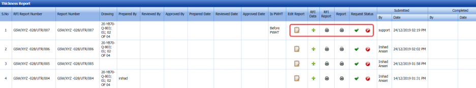
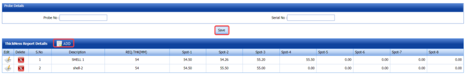
Figure 10.7: Thickness Report page
The page shows a list of added thickness inspection requests.
10.7.1 Add Thickness Inspection Report Details
If you want to add the thickness inspection report details,
1. Click (Edit icon) in the Edit Report column for the respective request.
The Probe Details window and the Thickness Report Details window opens.
2. In the Probe No box, enter the probe number.
3. In the Serial No box, enter the serial number.
4. Click Save.
5. Click (ADD button) in the Thickness Report Details
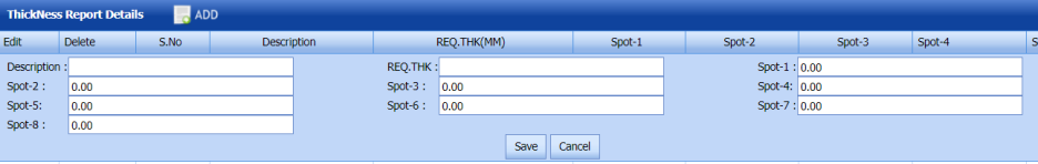
5. In the Description box, enter the description for the thickness report.
6. In the REQ-THK box, enter the required thickness value.
7. In the Spot-1 toSpot-8 boxes, enter the spot details.
8. Click Save.
10.7.2 Add Thickness Inspection Result Details
If you want to add the thickness inspection result details,
1. Click (Add icon) in the RFI Data column for the respective request.
The RFI Inspection Request List window opens.

2. In the ITP Ref box, enter the ITP reference detail.
3. In the Inspection Result field, select the inspection result.
4. In the Remarks box, enter your remarks if any.
5. Click Save.
10.7.3 Submit Thickness Inspection Result
Once you have added the thickness inspection result, the Request Status column in the Thickness Report page is appeared with
 (Submit and Reject icons). See Fig 10.7.
1. If you want to submit the thickness inspection result, click (Submit icon) in the Request Status Otherwise click (Reject icon) to reject the request.
Once the thickness inspection is updated, the completed status will be updated in the Completed column.
10.7.4 View an RFI Report for Thickness Inspection
If you want to view the RFI report for any thickness inspection, click (Print icon) provided in the RFI Report column.
10.7.5 View a Thickness Inspection Report
If you want to view the thickness inspection report, click (Print icon) provided in the Report column.
10.7.6 Attach a file into a Thickness Inspection Report
If you want to attach a file with any thickness inspection report in the Thickness Report page, you can use (Attach icon) provided in the Attachment column for the respective report. To know how to attach, see the topic, “Attach a file into a PQR”.
10.8 VPCI Report
The VPCI Report tab in the Inspection – Quality menu used to add the VPCI inspection result for added request.
1. Click VPCI Report in the Inspection – Quality
The VPCI Report page opens.
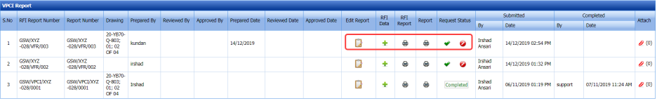
Figure 10.8: VPCI Report page
The page shows a list of added VPCI inspection requests.
10.8.1 Add VPCI Inspection Report Details
If you want to add the VPCI inspection report details,
1. Click (Edit icon) in the Edit Report column for the respective request.
The VPCI Report Details window and the VPCI Report window opens.
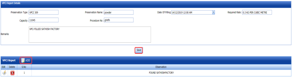
2. Check and edit the VPCI report details in the VPCI Report Details
3. Click Save.
4. Click (ADD button) in the VPCI Report
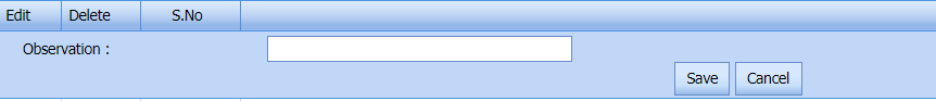
5. In the Observation box, enter the observation detail for VPCI.
6. Click Save.
10.8.2 Add VPCI Inspection Result Details
If you want to add the VPCI inspection result details,
1. Click (Add icon) in the RFI Data column for the respective request.
The RFI Inspection Request List window opens.

2. In the ITP Ref box, enter the ITP reference detail.
3. In the Inspection Result field, select the inspection result.
4. In the Remarks box, enter your remarks if any.
5. Click Save.
10.8.3 Submit VPCI Inspection Result
Once you have added the VPCI inspection result, the Request Status column in the VPCI Report page is appeared with (Submit and Reject icons). See Fig 10.8.
1. If you want to submit the VPCI inspection result, click(Submit icon) in the Request Status Otherwise click (Reject icon) to reject the request.
Once the VPCI inspection is updated, the completed status will be updated in the Completed column.
10.8.4 View an RFI Report for VPCI Inspection
If you want to view the RFI report for any VPCI inspection, click (Print icon) provided in the RFI Report column.
10.8.5 View a VPCI Inspection Report
If you want to view the VPCI inspection report, click (Print icon) provided in the Report column.
10.8.6 Attach a file into a VPCI Inspection Report
If you want to attach a file with any VPCI inspection report in the VPCI Report page, you can use (Attach icon) provided in the Attachment column for the respective report. To know how to attach, see the topic, “Attach a file into a PQR”.
10.9 Leak Test Report
The Leak Test Report tab in the Inspection – Quality menu used to add the leak test result for added request.
1. Click Leak Test Report in the Inspection – Quality
The Leak Test Report page opens.

Figure 10.9: Leak Test Report page
The page shows a list of added leak test requests.
10.9.1 Add Leak Test Report Details
If you want to add the leak test report details,
1. Click (Edit icon) in the Edit Report column for the respective request.
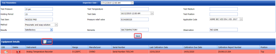
The Test Parameters window and the Equipment Details window opens.
2. In the Inspection Date box, select the inspection date.
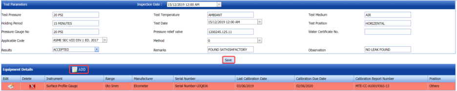
3. Check and edit the leak test report details in the Test Parameters
4. Click Save.
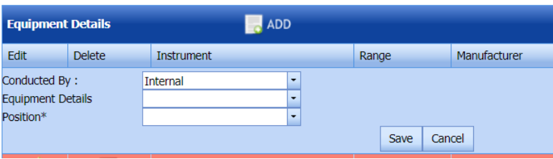
5. Click (ADD button) in the Equipment Details

6. In the Conducted By box, select whether the leak test is conducted Internally or Externally.
7. In the Equipment Details box, select the equipment detail from a drop-own list.
8. In the Position box, select a position from a drop-down list.
9. Click Save.
10.9.2 Add Leak Test Result Details
If you want to add the leak test result details,
1. Click (Add icon) in the RFI Data column for the respective request.
The RFI Inspection Request List window opens.

2. In the ITP Ref box, enter the ITP reference detail.
3. In the Inspection Result field, select the inspection result.
4. In the Remarks box, enter your remarks if any.
5. Click Save.
10.9.3 Submit Leak Test Result
Once you have added the leak test result, the Request Status column in the Leak Test Report page is appeared with (Submit and Reject icons). See Fig 10.9.
1. If you want to submit the leak test result, click (Submit icon) in the Request Status Otherwise click (Reject icon) to reject the request.
Once the leak test result is updated, the completed status will be updated in the Completed column.
10.9.4 View an RFI Report for Leak Test
If you want to view the RFI report for any leak test, click (Print icon) provided in the RFI Report column.
10.9.5 View a Leak Test Report
If you want to view the leak test report, click (Print icon) provided in the Report column.
10.9.6 Attach a file into a Leak Test Report
If you want to attach a file with any leak test report in the Leak Test Report page, you can use (Attach icon) provided in the Attachment column for the respective report. To know how to attach, see the topic, “Attach a file into a PQR”.
10.10 Hydrostatic Test Report
The Hydrostatic Test Report tab in the Inspection – Quality menu used to add the hydrostatic test result for added request.
1. Click Hydrostatic Test Report in the Inspection – Quality
The Hydrostatic Pressure Test Report page opens.
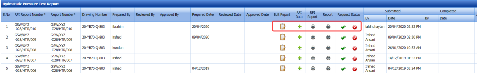
Figure 10.10: Hydrostatic Pressure Test Report page
The page shows a list of added hydrostatic test requests.
10.10.1 Add Hydrostatic Test Report Details
If you want to add the hydrostatic test report details,
1. Click (Edit icon) in the Edit Report column for the respective request.
The Test Parameters window, Metal Details window, and the Equipment Details window open.
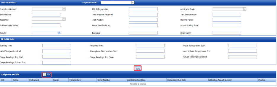
2. In the Inspection Date box, select the inspection date.
3. In the Test Parameters window, enter the test parameter data.
4. In the Metal Details window, enter the metal details.
5. Click Save.
6. Click (ADD button) in the Equipment Details

7. In the Conducted By box, select whether the hydrostatic test is conducted Internally or Externally.
8. In the Equipment Details box, select the equipment detail from a drop-own list.
9. In the Position box, select a position from a drop-down list.
10. Click Save.
10.10.2 Add Hydrostatic Test Result Details
If you want to add the hydrostatic test result details,
1. Click (Add icon) in the RFI Data column for the respective request.
The RFI Inspection Request List window opens.

2. In the ITP Ref box, enter the ITP reference detail.
3. In the Inspection Result field, select the inspection result.
4. In the Remarks box, enter your remarks if any.
5. Click Save.
10.10.3 Submit Hydrostatic Test Result
Once you have added the hydrostatic test result, the Request Status column in the Hydrostatic Pressure Test Report page is appeared with (Submit and Reject icons). See Fig 10.10.
1. If you want to submit the hydrostatic test result, click (Submit icon) in the Request Status Otherwise click (Reject icon) to reject the request.
Once the hydrostatic test result is updated, the completed status will be updated in the Completed column.
10.10.4 View an RFI Report for Hydrostatic Test
If you want to view the RFI report for any hydrostatic test, click (Print icon) provided in the RFI Report column.
10.10.5 View a Hydrostatic Test Report
If you want to view the hydrostatic test report, click (Print icon) provided in the Report column.
10.10.6 Attach a file into a Hydrostatic Test Report
If you want to attach a file with any hydrostatic test report in the Hydrostatic Pressure Test Report page, you can use (Attach icon) provided in the Attachment column for the respective report. To know how to attach, see the topic, “Attach a file into a PQR”.
10.11 Shell Side Hydrostatic Report
The Shell Side Hydrostatic Report tab in the Inspection – Quality menu used to add the shell side hydrostatic test result for added request.
1. Click Shell Side Hydrostatic Report in the Inspection – Quality
The Shell Side Hydrostatic Pressure Test Report page opens.
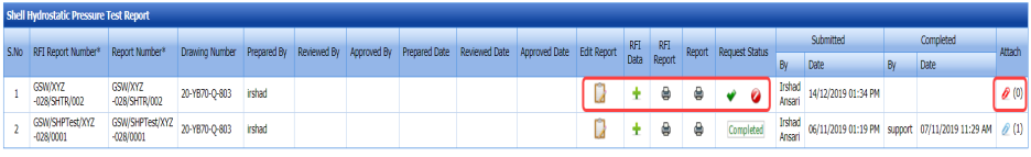
Figure 10.11: Shell Side Hydrostatic Pressure Test Report page
The page shows a list of added shell side hydrostatic test requests.
10.11.1 Add Shell Side Hydrostatic Test Report Details
If you want to add the shell side hydrostatic test report details,
1. Click (Edit icon) in the Edit Report column for the respective request.
The Test Parameters window, Metal Details window, and the Equipment Details window open.

2. In the Inspection Date box, select the inspection date.
3. In the Test Parameters window, enter the test parameter data.
4. In the Metal Details window, enter the metal details.
5. Click Save.
6. Click (ADD button) in the Equipment Details

7. In the Conducted By box, select whether the hydrostatic test is conducted Internally or Externally.
8. In the Equipment Details box, select the equipment detail from a drop-own list.
9. In the Position box, select a position from a drop-down list.
10. Click Save.
10.11.2 Add Shell Side Hydrostatic Test Result Details
If you want to add the shell side hydrostatic test result details,
1. Click (Add icon) in the RFI Data column for the respective request.
The RFI Inspection Request List window opens.

2. In the ITP Ref box, enter the ITP reference detail.
3. In the Inspection Result field, select the inspection result.
4. In the Remarks box, enter your remarks if any.
5. Click Save.
10.11.3 Submit Shell Side Hydrostatic Test Result
Once you have added the shell side hydrostatic test result, the Request Status column in the Shell Side Hydrostatic Pressure Test Report page is appeared with (Submit and Reject icons). See Fig 10.11.
1. If you want to submit the shell side hydrostatic test result, click (Submit icon) in the Request Status Otherwise click (Reject icon) to reject the request.
Once the shell side hydrostatic test result is updated, the completed status will be updated in the Completed column.
10.11.4 View an RFI Report for Shell Side Hydrostatic Test
If you want to view the RFI report for any shell side hydrostatic test, click (Print icon) provided in the RFI Report column.
10.11.5 View a Shell Side Hydrostatic Test Report
If you want to view the shell side hydrostatic test report, click (Print icon) provided in the Report column.
10.11.6 Attach a file into a Shell Side Hydrostatic Test Report
If you want to attach a file with any shell side hydrostatic test report in the Shell Side Hydrostatic Pressure Test Report page, you can use (Attach icon) provided in the Attachment column for the respective report. To know how to attach, see the topic, “Attach a file into a PQR”.
10.12 Pneumatic Pressure Report
The Pneumatic Test Report tab in the Inspection – Quality menu used to add the pneumatic pressure test result for added request.
1. Click Pneumatic Test Report in the Inspection – Quality
The Pneumatic Pressure Test Report page opens.
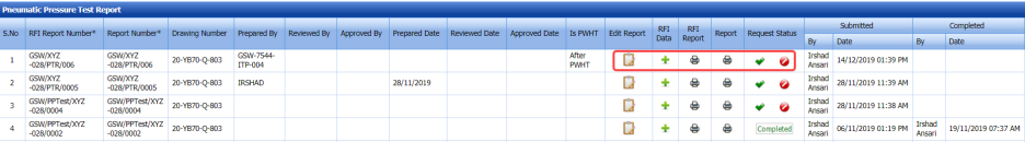
Figure 10.12: Pneumatic Pressure Test Report page
The page shows a list of added pneumatic pressure test requests.
10.12.1 Add Pneumatic Test Report Details
If you want to add the pneumatic pressure test report details,
1. Click (Edit icon) in the Edit Report column for the respective request.
The Test Parameters window and the Equipment Details window open.
2. In the Inspection Date box, select the inspection date.
3. Check and edit the pneumatic pressure test report details in the Test Parameters
4. Click Save.
5. Click (ADD button) in the Equipment Details window.
2. In the Conducted By box, select whether the pneumatic pressure test is conducted Internally or Externally.
3. In the Equipment Details box, select the equipment detail from a drop-own list.
4. In the Position box, select a position from a drop-down list.
5. Click Save.
10.12.2 Add Pneumatic Pressure Test Result Details
If you want to add the pneumatic pressure test result details,
1. Click (Add icon) in the RFI Data column for the respective request.
The RFI Inspection Request List window opens.

2. In the ITP Ref box, enter the ITP reference detail.
3. In the Inspection Result field, select the inspection result.
4. In the Remarks box, enter your remarks if any.
5. Click Save.
10.12.3 Submit Pneumatic Pressure Test Result
Once you have added the pneumatic pressure test result, the Request Status column in the Pneumatic Pressure Test Report page is appeared with (Submit and Reject icons). See Fig 10.12.
1. If you want to submit the pneumatic pressure test result, click (Submit icon) in the Request Status Otherwise click (Reject icon) to reject the request.
Once the pneumatic pressure test result is updated, the completed status will be updated in the Completed column.
10.12.4 View an RFI Report for Pneumatic Pressure Test
If you want to view the RFI report for any pneumatic pressure test, click (Print icon) provided in the RFI Report column.
10.12.5 View a Pneumatic Pressure Test Report
If you want to view the pneumatic pressure test report, click (Print icon) provided in the Report column.
10.12.6 Attach a file into a Pneumatic Pressure Test Report
If you want to attach a file with any pneumatic pressure test report in the Pneumatic Pressure Test Report page, you can use (Attach icon) provided in the Attachment column for the respective report. To know how to attach, see the topic, “Attach a file into a PQR”.
10.13 Flange Face Inspection Report
The Flange Face Inspection Report tab in the Inspection – Quality menu used to add the flange face inspection test result for added request.
1. Click Flange Face Inspection Report in the Inspection – Quality
The Flange Face Inspection Report page opens.
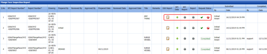
Figure 10.13: Flange Face Inspection Report page
The page shows a list of added flange face inspection requests.
10.13.1 Add Flange Face Inspection Report Details
If you want to add the flange face inspection report details,
1. Click (Edit icon) in the Edit Report column for the respective request.
The Report Photos window opens.
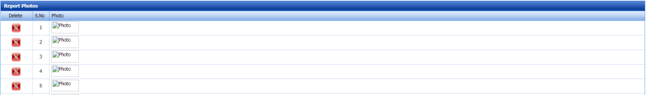
2. Add report photos.
10.13.2 Add Flange Face Inspection Result Details
If you want to add the flange face inspection result details,
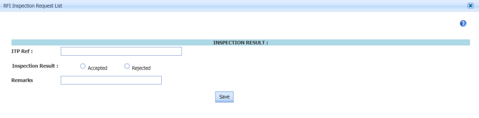
1. Click (Add icon) in the RFI Data column for the respective request.
The RFI Inspection Request List window opens.

2. In the ITP Ref box, enter the ITP reference detail.
3. In the Inspection Result field, select the inspection result.
4. In the Remarks box, enter your remarks if any.
5. Click Save.
10.13.3 Submit Flange Face Inspection Test Result
Once you have added the flange face inspection test result, the Request Status column in the Flange Face Inspection Report page is appeared with (Submit and Reject icons). See Fig 10.13.
1. If you want to submit the flange face inspection result, click (Submit icon) in the Request Status Otherwise click (Reject icon) to reject the request.
Once the flange face inspection result is updated, the completed status will be updated in the Completed column.
10.13.4 View an RFI Report for Flange Face Inspection Test
If you want to view the RFI report for any flange face inspection, click (Print icon) provided in the RFI Report column.
10.13.5 View a Flange Face Inspection Report
If you want to view the flange face inspection report, click (Print icon) provided in the Report column.
10.13.6 Attach a file into a Flange Face Inspection Report
If you want to attach a file with any flange face inspection report in the Flange Face Inspection Report page, you can use (Attach icon) provided in the Attachment column for the respective report. To know how to attach, see the topic, “Attach a file into a PQR”.
10.14 Drining and Dring Report
The Drining and Dring Report tab in the Inspection – Quality menu used to add the drining and dring inspection test result for added request.
1. Click Drining and Dring Reportin the Inspection – Quality
The Drining and Dring Report page opens.

Figure 10.14: Drining and Dring Report page
The page shows a list of added drining and dring inspection requests.
10.14.1 Add Drining and Dring Inspection Report Details
If you want to add the drining and dring inspection report details,
1. Click (Edit icon) in the Edit Report column for the respective request.
The Report Photos window opens.
2. Add report photos.
10.14.2 Add Drining and Dring Inspection Result Details
If you want to add the drining and dring inspection result details,
1. Click (Add icon) in the RFI Data column for the respective request.
The RFI Inspection Request List window opens.
2. In the ITP Ref box, enter the ITP reference detail.
3. In the Inspection Result field, select the inspection result.
4. In the Remarks box, enter your remarks if any.
5. Click Save.
10.14.3 Submit Drining and Dring Inspection Test Result
Once you have added the drining and dring inspection test result, the Request Status column in the Drining and Dring Report page is appeared with (Submit and Reject icons). See Fig 10.14.
1. If you want to submit the drining and dring inspection result, click (Submit icon) in the Request Status Otherwise click (Reject icon) to reject the request.
Once the drining and dring inspection result is updated, the completed status will be updated in the Completed column.
10.14.4 View an RFI Report for Drining and Dring Inspection Test
If you want to view the RFI report for any drining and dring inspection, click (Print icon) provided in the RFI Report column.
10.14.5 View a Drining and Dring Inspection Report
If you want to view the drining and dring inspection report, click (Print icon) provided in the Report column.
10.14.6 Attach a file into a Drining and Dring Inspection Report
If you want to attach a file with any drining and dring inspection report in the Drining and Dring Report page, you can use (Attach icon) provided in the Attachment column for the respective report. To know how to attach, see the topic, “Attach a file into a PQR”.
10.15 Shipment Report
The Shipment Report tab in the Inspection – Quality menu used to add the shipment inspection test result for added request.
1. Click Shipment Report in the Inspection – Quality
The Shipment Report page opens.
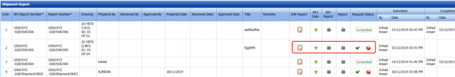
Figure 10.15: Shipment Report page
The page shows a list of added Shipment inspection requests.
10.15.1 Add Shipment Inspection Report Details
If you want to add the Shipment inspection report details,
1. Click (Edit icon) in the Edit Report column for the respective request.
The Report Photos window opens.
2. Add report photos.
10.15.2 Add Shipment Inspection Result Details
If you want to add the shipment inspection result details,
1. Click (Add icon) in the RFI Data column for the respective request.
The RFI Inspection Request List window opens.

2. In the ITP Ref box, enter the ITP reference detail.
3. In the Inspection Result field, select the inspection result.
4. In the Remarks box, enter your remarks if any.
5. Click Save.
10.15.3 Submit Shipment Inspection Result
Once you have added the shipment inspection result, the Request Status column in the Shipment Report page is appeared with
 (Submit and Reject icons). See Fig 10.15.
1. If you want to submit the shipment inspection result, click (Submit icon) in the Request Status Otherwise click (Reject icon) to reject the request.
Once the shipment inspection result is updated, the completed status will be updated in the Completed column.
10.15.4 View an RFI Report for Shipment Inspection Test
If you want to view the RFI report for any shipment inspection, click (Print icon) provided in the RFI Report column.
10.15.5 View a Shipment Inspection Report
If you want to view the shipment inspection report, click (Print icon) provided in the Report column.
10.15.6 Attach a file into a Shipment Inspection Report
If you want to attach a file with any shipment inspection report in the Shipment Report page, you can use (Attach icon) provided in the Attachment column for the respective report. To know how to attach, see the topic, “Attach a file into a PQR”.
10.16 Name Plate Report
The Name Plate Report tab in the Inspection – Quality menu used to add the name plate test result for added request.
1. Click Name Plate Report in the Inspection – Quality
The Name Plate Report page opens.
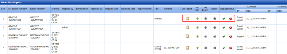
Figure 10.16: Name Plate Report page
The page shows a list of added name plate inspection requests.
10.16.1 Add Name Plate Inspection Report Details
If you want to add the name plate inspection report details,
1. Click (Edit icon) in the Edit Report column for the respective request.
The Report Photos window opens.
2. Add report photos.
10.16.2 Add Name Plate Inspection Result Details
If you want to add the name plate inspection result details,
1. Click (Add icon) in the RFI Data column for the respective request.
The RFI Inspection Request List window opens.
2. In the ITP Ref box, enter the ITP reference detail.
3. In the Inspection Result field, select the inspection result.
4. In the Remarks box, enter your remarks if any.
5. Click Save.
10.16.3 Submit Name Plate Inspection Result
Once you have added the name plate inspection result, the Request Status column in the Name Plate Report page is appeared with (Submit and Reject icons). See Fig 10.16.
1. If you want to submit the name plate inspection result, click (Submit icon) in the Request Status Otherwise click (Reject icon) to reject the request.
Once the name plate inspection result is updated, the completed status will be updated in the Completed column.
10.16.4 View an RFI Report for Name Plate Inspection Test
If you want to view the RFI report for any name plate inspection, click (Print icon) provided in the RFI Report column.
10.16.5 View a Name Plate Inspection Report
If you want to view the name plate inspection report, click (Print icon) provided in the Report column.
10.16.6 Attach a file into a Name Plate Inspection Report
If you want to attach a file with any name plate inspection report in the Name Plate Report page, you can use (Attach icon) provided in the Attachment column for the respective report. To know how to attach, see the topic, “Attach a file into a PQR”
10.17 Stamp Verification/Others Report
The Stamp Verification Report tab in the Inspection – Quality menu used to add the stamp verification result for added request.
1. Click Stamp Verification Report in the Inspection – Quality
The Stamp Verification Report page opens.
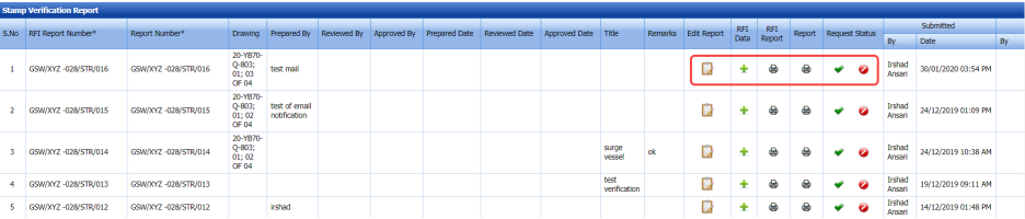
Figure 10.17: Stamp Verification Report page
The page shows a list of added stamp verification requests.
10.17.1 Add Stamp Verification Report Details
If you want to add the stamp verification report details,
1. Click (Edit icon) in the Edit Report column for the respective request.
The Stamp Verification Result window opens.
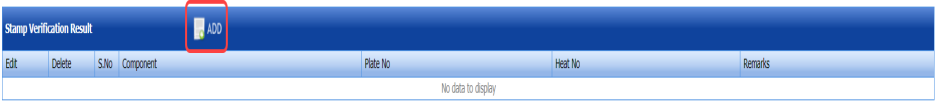
2. Click  (ADD button) in the Stamp Verification Result
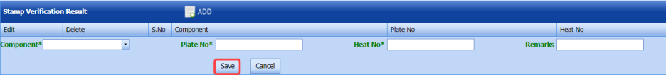
3. In the Component box, select a component from a drop-down list.
4. In the Plate No box, enter the plate number.
5. In the Heat No box, enter the heat number.
6. In the Remarks box, enter your remarks if any.
7. Click Save.
10.17.2 Add Stamp Verification Result Details
If you want to add the stamp verification result details,
1. Click (Add icon) in the RFI Data column for the respective request.
The RFI Inspection Request List window opens.
2. In the ITP Ref box, enter the ITP reference detail.
3. In the Inspection Result field, select the inspection result.
4. In the Remarks box, enter your remarks if any.
5. Click Save.
10.17.3 Submit Stamp Verification Result
Once you have added the stamp verification result, the Request Status column in the Stamp Verification Report page is appeared with (Submit and Reject icons). See Fig 10.17.
1. If you want to submit the stamp verification result, click (Submit icon) in the Request Status Otherwise click
(Reject icon) to reject the request.
Once the stamp verification result is updated, the completed status will be updated in the Completed column.
10.17.4 View an RFI Report for Stamp Verification
If you want to view the RFI report for any stamp verification inspection, click (Print icon) provided in the RFI Report column.
10.17.5 View a Stamp Verification Report
If you want to view the stamp verification report, click (Print icon) provided in the Report column.
10.17.6 Attach a file into a Stamp Verification Report
If you want to attach a file with any stamp verification report in the Stamp Verification Report page, you can use (Attach icon) provided in the Attachment column for the respective report. To know how to attach, see the topic, “Attach a file into a PQR”.
10.18 Dishend Dimension Report
The Dishend Dimension Report tab in the Inspection – Quality menu used to add the dishend dimension inspection test result for added request.
1. Click Dishend Dimension Report in the Inspection – Quality
The Dishend Dimension Report page opens.
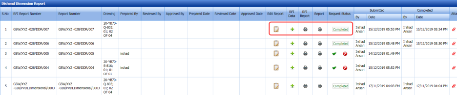
Figure 10.18: Dishend Dimension Report page
The page shows a list of added dishend dimension inspection requests.
10.18.1 Add Dishend Dimension Inspection Report Details
If you want to add the dishend dimension inspection report details,
1. Click (Edit icon) in the Edit Report column for the respective request.
The Dishend Dimension Details, Required Dimension, Checked Dimension, and Report Photos window opens.
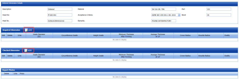
2. Check and edit the details in the Dishend Dimension Details
3. Click (ADD button) in the Required Dimension
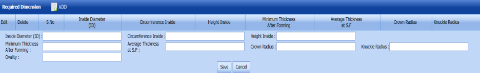
4. In the Inside Diameter (ID) box, enter the inside diameter value.
5. In the Circumference Inside box, enter the inside circumference value.
6. In the Height Inside box, enter the inside height value.
7. In the Minimum Thickness box, enter the minimum thickness value.
8. In the Average Thickness box, enter the average thickness value.
9. In the Crown Radius box, enter the crown radius value.
10. In the Knuckle Radius box, enter the knuckle radius value.
11. In the Ovality box, enter the ovality value.
12. Click Save.
The required dimension details are saved.
13. Click (ADD button) in the Checked Dimension
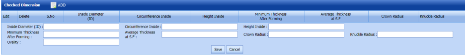
14. Enter the checked dimension details in the Checked Dimension
15. Add report photos.
10.18.2 Add Dishend Dimension Inspection Result Details
If you want to add the dishend dimension inspection result details,
1. Click (Add icon) in the RFI Data column for the respective request.
The RFI Inspection Request List window opens.
2. In the ITP Ref box, enter the ITP reference detail.
3. In the Inspection Result field, select the inspection result.
4. In the Remarks box, enter your remarks if any.
5. Click Save.
10.18.3 Submit Dishend Dimension Inspection Test Result
Once you have added the dishend dimension inspection test result, the Request Status column in the Dishend Dimension Report page is appeared with (Submit and Reject icons). See Fig 10.18.
1. If you want to submit the dishend dimension inspection result, click  (Submit icon) in the Request Status Otherwise click
 (Reject icon) to reject the request.
Once the dishend dimension inspection result is updated, the completed status will be updated in the Completed column.
10.18.4 View an RFI Report for Dishend Dimension Inspection Test
If you want to view the RFI report for any dishend dimension inspection, click (Print icon) provided in the RFI Report column.
10.18.5 View a Dishend Dimension Inspection Report
If you want to view the dishend dimension inspection report, click (Print icon) provided in the Report column.
10.18.6 Attach a file into a Dishend Dimension Inspection Report
If you want to attach a file with any dishend dimension inspection report in the Dishend Dimension Report page, you can use (Attach icon) provided in the Attachment column for the respective report. To know how to attach, see the topic, “Attach a file into a PQR”.
10.19 Dishend Thickness Report
The Dishend Thickness Report tab in the Inspection – Quality menu used to add the dishend thickness inspection test result for added request.
1. Click Dishend Thickness Report in the Inspection – Quality
The Dishend Thickness Report page opens.
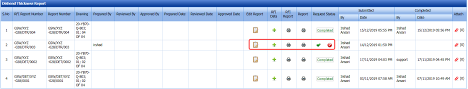
Figure 10.19: Dishend Thickness Report page
The page shows a list of added dishend thickness inspection requests.
10.19.1 Add Dishend Thickness Inspection Report Details
If you want to add the dishend thickness inspection report details,
1. Click (Edit icon) in the Edit Reportcolumn for the respective request.
The Dishend Thickness Details and Required Thickness windows open.
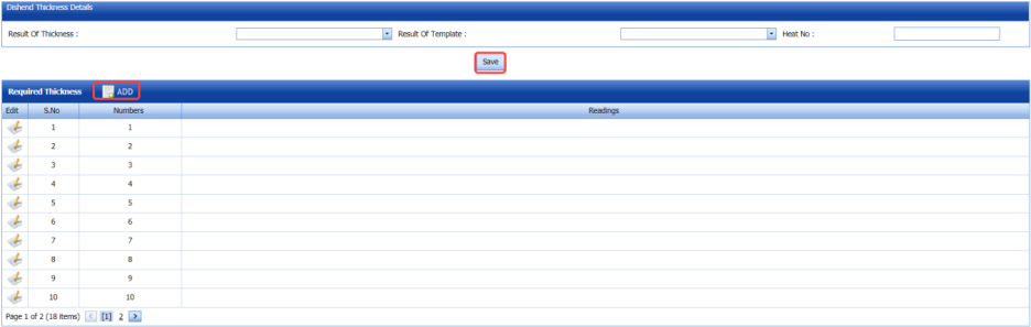
2. Check and edit the details in the Dishend Thickness Details
3. Click (ADD button) in the Required Thickness
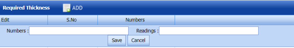
4. In the Numbers box, enter the number value.
5. In the Readings box, enter the readings value.
6. Click Save.
The required thickness details are saved.
10.19.2 Add Dishend Thickness Inspection Result Details
If you want to add the dishend thickness inspection result details,
1. Click (Add icon) in the RFI Data column for the respective request.
The RFI Inspection Request List window opens.
2. In the ITP Ref box, enter the ITP reference detail.
3. In the Inspection Result field, select the inspection result.
4. In the Remarks box, enter your remarks if any.
5. Click Save.
10.19.3 Submit Dishend Thickness Inspection Test Result
Once you have added the dishend thickness inspection test result, the Request Status column in the Dishend Thickness Report page is appeared with (Submit and Reject icons). See Fig 10.19.
1. If you want to submit the dishend thickness inspection result, click (Submit icon) in the Request Status Otherwise click (Reject icon) to reject the request.
Once the dishend thickness inspection result is updated, the completed status will be updated in the Completed column.
10.19.4 View an RFI Report for Dishend Thickness Inspection Test
If you want to view the RFI report for any dishend thickness inspection, click  (Print icon) provided in the RFI Report column.
10.19.5 View a Dishend Thickness Inspection Report
If you want to view the dishend thickness inspection report, click (Print icon) provided in the Report column.
10.19.6 Attach a file into a Dishend Thickness Inspection Report
If you want to attach a file with any dishend thickness inspection report in the Dishend Thickness Report page, you can use  (Attach icon) provided in the Attachment column for the respective report. To know how to attach, see the topic, “Attach a file into a PQR”.
10.20 Blasting and Painting Report
The Blasting and Painting Report tab in the Inspection – Quality menu used to add the blasting and painting inspection test result for added request.
1. Click Blasting and Painting Report in the Inspection – Quality
The Blasting and Painting Report page opens.
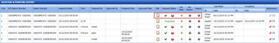
Figure 10.20: Blasting and Painting Report page
The page shows a list of added blasting and painting inspection requests.
10.20.1 Add Blasting and Painting Inspection Report Details
If you want to add the blasting and painting inspection report details,
1. Click (Edit icon) in the Edit Report column for the respective request.
The page shows a new window to add the result details.
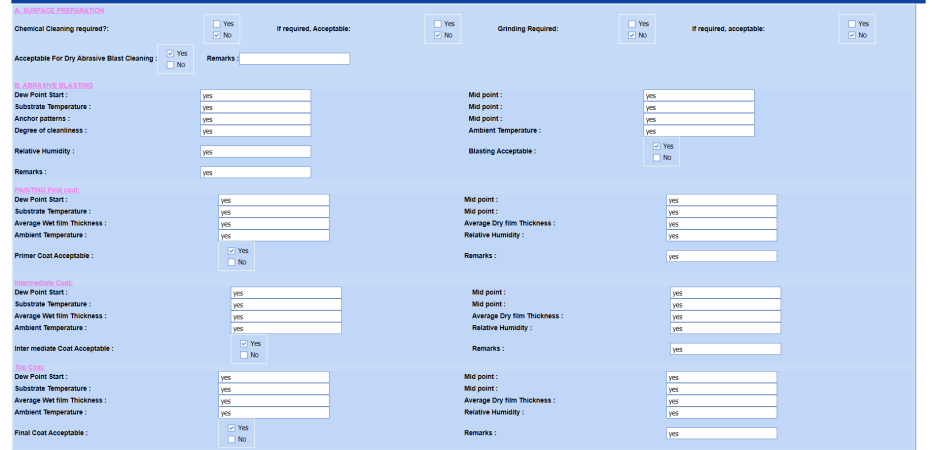
2. In the SURFACE PREPARATION field, enter the inspection details for surface preparation.
3. In the ABRASIVE BLASTING field, enter the inspection details for abrasive preparation.
4. In the Painting First Coat field, enter the inspection details for first coat painting.
5. In the Intermediate Coat field, enter the inspection details for intermediate coat.
6. In the Top Coat field, enter the inspection details for top coat.
10.20.2 Add Blasting and Painting Inspection Result Details
If you want to add the blasting and painting inspection result details,
1. Click (Add icon) in the RFI Data column for the respective request.
The RFI Inspection Request List window opens.
2. In the ITP Ref box, enter the ITP reference detail.
3. In the Inspection Result field, select the inspection result.
4. In the Remarks box, enter your remarks if any.
5. Click Save.
10.20.3 Submit Blasting and Painting Inspection Result
Once you have added the blasting and painting inspection result, the Request Status column in the Blasting and Painting Report page is appeared with (Submit and Reject icons). See Fig 10.20.
1. If you want to submit the blasting and painting inspection result, click (Submit icon) in the Request Status Otherwise click (Reject icon) to reject the request.
Once the blasting and painting inspection result is updated, the completed status will be updated in the Completed column.
10.20.4 View an RFI Report for Blasting and Painting Inspection Test
If you want to view the RFI report for any blasting and painting inspection, click (Print icon) provided in the RFI Report column.
10.20.5 View a Blasting and Painting Inspection Report
If you want to view the blasting and painting inspection report, click (Print icon) provided in the Report column.
10.20.6 Attach a file into a Blasting and Painting Inspection Report
If you want to attach a file with any blasting and painting inspection report in the Blasting and Painting Report page, you can use (Attach icon) provided in the Attachment column for the respective report. To know how to attach, see the topic, “Attach a file into a PQR”.
10.21 Miscellaneous Report
The Miscellaneous Report tab in the Inspection – Quality menu used to add the vessel NDT inspection test result for added request.
1. Click Miscellaneous Report in the Inspection – Quality
The Vessel NDT Report page opens.
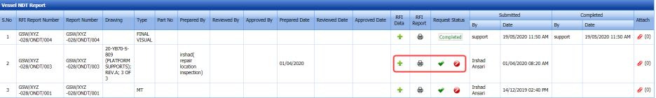
Figure 10.21: Vessel NDT Report page
The page shows a list of added vessel NDT inspection requests.
10.21.1 Add Vessel NDT Inspection Result Details
If you want to add the vessel NDT inspection result details,
1. Click (Add icon) in the RFI Data column for the respective request.
The RFI Inspection Request List window opens.
2. In the ITP Ref box, enter the ITP reference detail.
3. In the Inspection Result field, select the inspection result.
4. In the Remarks box, enter your remarks if any.
5. Click Save.
10.21.2 Submit Vessel NDT Inspection Result
Once you have added the vessel NDT inspection result, the Request Status column in the Vessel NDT Report page is appeared with (Submit and Reject icons). See Fig 10.21.
1. If you want to submit the vessel NDT inspection result, click (Submit icon) in the Request Status Otherwise click (Reject icon) to reject the request.
Once the vessel NDT inspection result is updated, the completed status will be updated in the Completed column.
10.21.3 View an RFI Report for Vessel NDT Inspection
If you want to view the RFI report for any vessel NDT inspection, click (Print icon) provided in the RFI Report column.
10.21.4 Attach a file into a Vessel NDT Inspection Report
If you want to attach a file with any vessel NDT inspection report in the Vessel NDT Report page, you can use (Attach icon) provided in the Attachment column for the respective report. To know how to attach, see the topic, “Attach a file into a PQR”.
10.22 PWHT Report
The PWHT Report tab in the Inspection – Quality menu used to add the PWHT inspection result for added request.
1. Click PWHT Report in the Inspection – Quality
The PWHT Report page opens.

Figure 10.22: PWHT Report page
The page shows a list of added PWHT inspection requests.
10.22.1 Add PWHT Inspection Report Details
If you want to add the PWHT inspection report details,
1. Click (Edit icon) in the Edit Report column for the respective request.
The page shows the Test Parameters and PWHT Test Result windows.
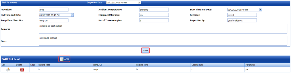
2. In the Test Parameters window, check and edit the test parameters data.
3. Click (ADD button) in the PWHT Test Result window.

4. In the Heating Rate box, enter the heating rate.
5. In the Temp box, enter the temperature value.
6. In the Holding Time box, enter the holding time range.
7. In the Cooling Rate box, enter the cooling rate value.
8. In the Parameter box, enter the parameter value.
9. Click Save.
10.22.2 Add PWHT Inspection Result Details
If you want to add the PWHT inspection result details,
1. Click (Add icon) in the RFI Data column for the respective request.
The RFI Inspection Request List window opens.
2. In the ITP Ref box, enter the ITP reference detail.
3. In the Inspection Result field, select the inspection result.
4. In the Remarks box, enter your remarks if any.
5. Click Save.
10.22.3 Submit PWHT Inspection Result
Once you have added the PWHT inspection result, the Request Status column in the PWHT Report page is appeared with (Submit and Reject icons). See Fig 10.22.
1. If you want to submit the PWHT inspection result, click (Submit icon) in the Request Status Otherwise click (Reject icon) to reject the request.
Once the PWHT inspection result is updated, the completed status will be updated in the Completed column.
10.22.4 View an RFI Report for PWHT Inspection Test
If you want to view the RFI report for any PWHT inspection, click (Print icon) provided in the RFI Report column.
10.22.5 View a PWHT Inspection Report
If you want to view the PWHT inspection report, click (Print icon) provided in the Report column.
10.22.6 Attach a file into a PWHT Inspection Report
If you want to attach a file with any PWHT inspection report in the PWHT Report page, you can use (Attach icon) provided in the Attachment column for the respective report. To know how to attach, see the topic, “Attach a file into a PQR”.
10.23 Pre-welding Inspection Report
The Pre-welding Inspection Report tab in the Inspection – Quality menu used to add the pre-welding inspection result for added request.
1. Click Pre-welding Inspection Report in the Inspection – Quality
The Pre-welding Inspection Report page opens.

Figure 10.23: Pre-welding Inspection Report page
The page shows a list of added pre-welding inspection requests.
10.23.1 Add Pre-welding Inspection Result Details
If you want to add the pre-welding inspection result details,
1. Click (Add icon) in the RFI Data column for the respective request.
The RFI Inspection Request List window opens.
2. In the ITP Ref box, enter the ITP reference detail.
3. In the Inspection Result field, select the inspection result.
4. In the Remarks box, enter your remarks if any.
5. Click Save.
10.23.2 Submit Pre-welding Inspection Result
Once you have added the pre-welding inspection result, the Request Status column in the Pre-welding Inspection Report page is appeared with (Submit and Reject icons). See Fig 10.23.
1. If you want to submit the pre-welding inspection result, click (Submit icon) in the Request Status Otherwise click (Reject icon) to reject the request.
Once the pre-welding inspection result is updated, the completed status will be updated in the Completed column.
10.23.3 View an RFI Report for Pre-welding Inspection
If you want to view the RFI report for any pre-welding inspection, click (Print icon) provided in the RFI Report column.
10.23.4 Attach a file into a Pre-welding Inspection Report
If you want to attach a file with any pre-welding inspection report in the Pre-welding Inspection Report page, you can use (Attach icon) provided in the Attachment column for the respective report. To know how to attach, see the topic, “Attach a file into a PQR”.
No Comments