
Piping
6.0 Piping
6.1 Radiographic Testing (RT)
RT inspection method is one of the types of NDT inspection used to conduct inspection in the piping project by using either x-rays or gamma rays.
Once the NDT inspection request is added with the selection of RT type by using the NDT Inspection Request tab, the added inspection request will be moved here. After completing RT inspection, you can add the RT inspection result details by using this RT tab.
-
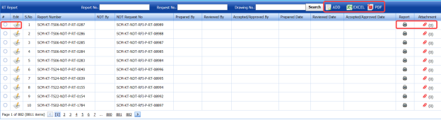
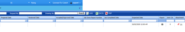
Click Radiographic Testing (RT) in the Piping menu.
The RT Report page opens.

Figure 6.1: RT Report page
6.11 Add an RT Report
If you want to add an RT report, do the following steps,
-
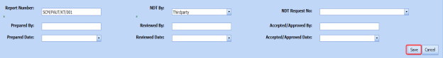
Click (ADD button) in the RT Report page. See Fig 6.1.
The RT Report page opens a new window to add an RT report.

 Note: The fields notified with a symbol (*) are mandatory. You must enter the relevant details in that fields before saving.
 Tip: A report number for a new RT report will be updated automatically in the Report Number box. If you want change the report number, you can change.
 - In the NDT By box, select the requisition detail of NDT whether by third party or internal from a drop-down list.
- In the NDT Request No box, select an RT request number from a drop-down list.
- In the Prepared By box, enter the name of a person who has prepared the RT report.
- In the Prepared Date box, select the prepared date of the RT report.
- In the Reviewed By box, enter the name of a person who has reviewed the RT report.
- In the Reviewed Date box, select the reviewed date of the RT report.
-
In the Accepted/Approved By boxes, enter the name of a person who has accepted/approved the RT report.
- In the Accepted/Approved Date box, select the accepted/approved date of the RT report.
-
Click Save.
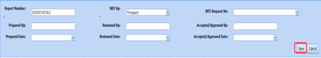


The RT report is successfully added. Once you have added the RT report, you must add RT inspection results.
6.1.2 Add RT Inspection Results
If you want to add the RT inspection results for the added RT report, do the following steps,
- Click the respective added RT report in the RT Report See Fig 6.1.
The RT Report page shows RT Results, Joint Results, and Report Photos windows to add RT results.
Figure 6.1.1: RT Results page
- In the Inspection Date box, select the date of inspection.
- In the Image Quality Indicator (IQI) box, select IQI from a drop-down list.
- In the Source & Size (MM) box, select the RT source and their size from a drop-down list.
- In the Density box, enter the radiographic density range.
- In the Code box, select the code of the material from a drop-down list.
- In the Procedure Number box, select the procedure number from a drop-down list.
- In the Sensitivity (%)box, set the radiographic sensitivity by using up and down arrows.
- In the Developing Time (Mins)box, set the developing time by using up and down arrows.
- In the Film/ Type box, select the name of a film including type from a drop-down list.
- In the Acceptance Criteria box, select the acceptance criteria from a drop-down list.
-
In the Source to Film Distance (SFD) box, enter the distance range between the source and the film.
- In the Focus Film Distance (FFD)box, enter the focus film distance range.
- In the Source box, select any one source option whether inside, outside, or other.
- In the Technique box, select the radiographic technique from a drop-down list.
- In the Examination Stage box, select the examination stage from the specified options.
- In the Material box, select the material from a drop-down list.
- In the Surface Condition box, select the condition of the surface from the specified options.
- In the Placement of IQI box, select any one option from source side and film side.
- In the Source Strength (Ci)box, enter the source strength value.
- In the Exposure Time (Mins)box, set the exposure time by using up and down arrows.
- In the Remarks box, enter your remarks if any.
-
Click Save RT Details.
The RT details are successfully updated. Once you have updated the RT details, you must add marker results of added joints.

 Note: Once you have added RT details, you can save the added RT details and reuse the saved details while you adding RT details for any other RT report.

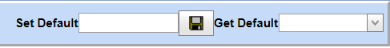
- To save the added RT details, enter any name in the Set Default box and click .
-
If you want to add the same RT details for any other RT report, select the name in the Get Default.
The saved details will be automatically updated in the respective boxes.
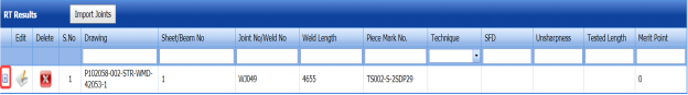
6.1.2.1 Add Marker Results for Joints
The RT Results window shows a list of joints added for the RT inspection. If you want to add marker results for the respective joints,
- Click
 (Add icon) for the respective joint.
The Marker Results window opens with a list of markers of the respective joint.
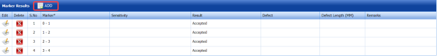
- If you want to add any additional markers, click
 (ADD button).
The Marker Results window shows a new window to add a new marker.

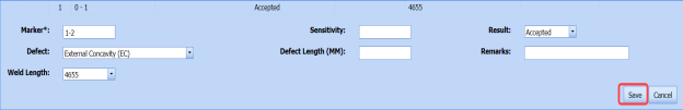
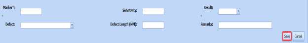
-
-
In the Marker box, enter the marker number.
- In the Sensitivity box, enter the sensitivity range.
- In the Result box, select the marker result from the given result options.
- In the Defect box, select the defect type if any.
- In the Defect Length (MM)box, enter the defect length value.
- In the Remarks box, enter your remarks if any.
-
Click Save. The marker is added and listed in the Marker Results window.
-
-
-
If you want to update marker results,
-
- Click
 (Edit icon) in the Edit column for the respective marker results.
A new window opens to edit the marker results.
-
Click any box where you want to edit the details, and edit the marker results.
-
Click Save.
- Click
-
- If you want delete any existing marker results, click
 (Delete icon) for the respective marker results.


9.1.2.2 Import Additional Joints
If you want to import additional joints for the RT inspection,
- Click
 (Import Joints button) in the RT Results See Fig 6.1.1.
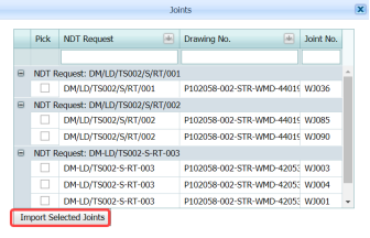
The Joints window opens with a list of joints.

-
Select the joints you want to import.
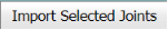
- Click
 (Import Selected Joints button).
The selected joints are imported for the respective RT inspection. Once you have imported the joints, you must perform the RT inspection and add the marker results for the added joints.


6.1.2.3 Add Report Photos
If you want to add any report photos for the updated RT results,
- Click
 (ADD button) in the Report Photos box in the RT Results See Fig 6.1.1.

- Click
 (Browse button) to browse a photo stored in your computer.
 -
Click Upload.
The selected photo will be updated.


6.1.3 Attach a File into an RT Report
If you want to attach any file with any RT report listed in the RT Report page, you can attach the file by using (Attach icon) in the Attachment column. To know how to attach, follow the procedures given in the topic “Attach a file into P&ID”.
6.1.4 View an NDT – RT Report
If you want to view an NDT - RT report, click (print icon) provided in the Report column of the RT Report page. See Fig 6.1.
6.1.5 Edit an RT Report
If you want to edit any existing RT report in the RT Report page, do the following,
- Click
 (Edit icon) in the Edit column for the respective RT report. See Fig 6.1.
A new window opens to edit the RT report.

-
Click any box where you want to edit the details, and then edit the details in the respective box.
-
Click Save.
-
If you want to edit the RT inspection results of any report, click the respective report and change the results.


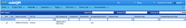
6.1.6 Export RT Report List
You can export a list of RT reports added in the RT Report page in both the pdf and excel formats by using  (PDF button) and
  (Excel button). To know how to export, see the topic, “Export P&ID list”.
6.1.7 Filter an RT Report
If you want to filter any RT report, do one of the following,

-
If you want to filter any RT report based on the report number, enter the corresponding report number in the Report No box in the RT Report page, and then Click Search.
- If you want to filter any RT report based on the request number, enter the corresponding request number in the Request No box in the RT Report page, and then Click Search.
- If you want to filter any RT report based on the drawing number, enter the corresponding drawing number in the Drawing No box in the RT Report page, and then Click Search.
6.2 Ultrasonic Testing (UT)
The UT method is one of the NDT inspection methods used for performing inspection in the piping project by using high frequency sound waves.
Once the NDT inspection request is added with the selection of UT type by using the NDT Inspection Request tab, the added inspection request will be moved here. After completing UT inspection, you can add the UT inspection result details by using this UT tab.
-
Click the Ultrasonic Testing (UT) tab in the Piping menu.
The UT Report page opens.
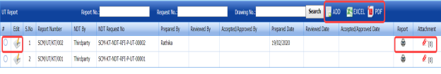
Figure 6.2: UT Report page

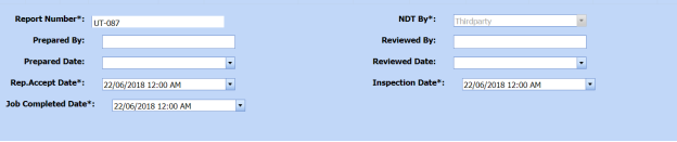
6.2.1 Add an UT Report
If you want to add an UT report, do the following,
-
Click
 (ADD button) in the UT Report page. See Fig 6.2.
A new window opens to add an UT report.

 Note: The fields notified with a symbol (*) are mandatory. You must enter the relevant details in that fields before saving.
 Tip: A report number for a new UT report will be updated automatically in the Report Number box.
 - In the NDT By box, select the requisition of NDT whether by third party or internal from a drop-down list.
-
In the NDT Request No box, select an UT request number from a drop-down list.
- In the Prepared By box, enter the name of a person who has prepared the UT report.
- In the Prepared Date box, select the prepared date of the UT report.
- In the Reviewed By box, enter the name of a person who has reviewed the UT report.
- In the Reviewed Date box, select the reviewed date of the UT report.
-
In the Accepted/Approved By boxes, enter the name of a person who has accepted/approved the UT report.
- In the Accepted/Approved Date box, select the accepted/approved date of the UT report.
- In the Accept Date box, select the report accept date.
- Click Save.


The UT report is successfully added. Once you have added the UT report, you must add UT results for the respective added UT report.
6.2.2 Add UT Results
If you want to add the UT results for the respective UT report, do the following,
-
Click the respective added UT report in the UT Report page. See Fig 6.2.
The UT Report page shows UT Results, Probe & Cable Details, Reference Setting Details, UT Results, and Report Photos windows.
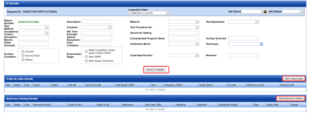
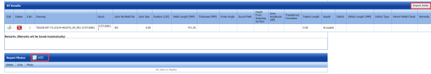
Figure 6.2.1: UT Results page
-
In the Inspection Date box, select the date of UT inspection.
-
In the Test Method box, select the test method from a drop-down list.
-
In the Description box, enter the description about the UT inspection.
-
In the Material box, select the material from a drop-down list.
-
In the Test Equipment box, select the test equipment from a drop-down list.
-
In the Acceptance Criteria box, select the acceptance criteria from a drop-down list.
-
In the Couplant box, select the couplant material from a drop-down list.
-
In the Test Procedure No box, select the test procedure number from a drop-down list.
-
In the Simulation Blocks box, enter the detail of simulation blocks.
-
In the Ref. Hole Diameter box, enter the diameter value of the reference hole.
-
In the Sensitivity Setting box, enter the information about the sensitivity setting.
-
In the Sides Scanned box, enter the details of the sides that are scanned.
-
In the Special Equipment box, enter the name of the special equipment if any.
-
In the Computerized Program Name box, enter the computerized program name.
-
In the Surface Scanned box, the details of the surfaces that are scanned.
-
In the Scan Limitation box, enter the limitation range of scanning.
-
In the Code/Specification box, select the specification from a drop-down list.
-
In the Calibration Block box, select the calibration block from a drop-down list.
-
In the Technique box, select the technique from a drop-down list.
-
In the Examination Stage box, select the examination stage from the specified options.
-
In the Surface Condition box, select the surface condition from the specified options.
-
In the Remarks box, enter your remarks if any.
-
Click Save UT Details.


The UT details are successfully updated. Once you have updated the UT details, you must add the probe and cable details for the UT inspection.
 Note: Once you have added UT details, you can save the added UT details and reuse the saved details while you adding UT details for any other UT report.

- To save the added UT details, enter any name in the Set Default box and click
 .
.
The added details will be saved in the given name.
-
If you want to add the same UT details for any other UT report, select the name in the Get Default.

The saved details will be automatically updated in the respective boxes.
6.2.2.1 Add Probe & Cable Details
If you want to add probe and cable details for the updated UT results,
- Click (Add Probe/ Cable button) in the Probe& Cable Details See Fig 6.2.1.
A new window opens to add the probe and cable details.

- In the Probe box, select a probe from a drop-down list.
- In the Cable box, select a cable from a drop-down list.
- In the dB box, enter the reference decibel range.
- In the Surf Comp dB box, enter the decibel range of the surface component.
- In the Test Range (MM) box, enter the test range in millimeters.
- In the Reference Level box, enter the reference level detail.
- In the Scanning dB box, enter the scanning decibel range.
- In the TR Loss box, enter the transmission loss detail.
- Click Save.

The probe and cable details are successfully added. Once you have added the probe and cable details, you must add the reference setting details.
6.2.2.2 Add Reference Setting Details
If you want to add the reference setting details for the updated UT results,
-
Click
 (Add Reference Setting button) in the Reference Setting Details window. See Fig 6.2.1.
A new window opens to add the reference setting details.

-
In the Reference Block box, select the reference block from a drop-down list.
-
In the Probe Sr. No box, select the serial number of the probe from a drop-down list.
-
In the Reference box, enter the reference detail.
-
In the Eqpt Gain (dB) box, enter the equipment gain in decibels.
-
In the Damping box, enter the damping ratio.
- In the Rejection box, enter the rejection detail.
- In the Amplitude Height box, enter the amplitude height range.
- In the Skip box, enter the skip detail.
- In the Beam Path box, enter the beam path detail.
-
In the Range box, enter the range detail.
-
Click Save.

The reference setting details are successfully added. Once you have added the reference setting details, you must add the inspection results for added joints.
6.2.2.3 Add UT Results
The UT Results window shows a list of joints added for the UT inspection. If you want to add UT results for joints,
-
Click
 (Edit icon) for the respective UT results listed in the UT Results window.
The UT Results window opens with the added UT details.

- In the Result box, update your UT inspection results whether Accepted, Rejected, or Cancelled.
- In the Remarks box, enter your remarks if any.
-
Click Save.


6.2.2.4 Import Additional Joints
If you want to add more joints, you can add by using the import joints option. To import joints,
- Click
 (Import Joints button) in the UT Results See Fig 6.2.1.
The Joints window opens with a list of joints.

- Select the joints you want to import.
- Click
 (Import Selected Joints button).

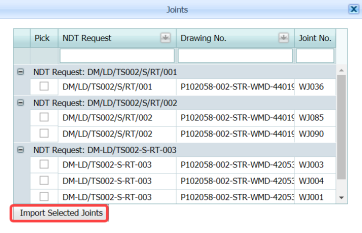

The selected joints are imported for the respective UT and listed in the UT Results window. Once you have imported the joints, you must add the UT results for the imported joints.
6.2.2.5 Add Report Photos
If you want to add any report photos for the updated UT results,
- Click
 (ADD button) in the Report Photos box in the UT Results See Fig 6.2.1.

- Click
 (Browse button) to browse a photo stored in your computer.
 -
Click Upload.
The selected photo will be updated.


The UT results will be updated successfully.
6.2.3 Attach a File into an UT Report
If you want to attach any file with any UT report listed in the UT Report page, you can attach the file by using  (Attach icon) in the Attachment column. To know how to attach, follow the procedures given in the topic “Attach a file into P&ID”.
6.2.4 View an NDT – UT Report
If you want to print an NDT - UT report, click  (print icon) provided in the Report column of the UT Report page. See Fig 6.2.
6.2.5 Edit an UT Report
If you want to edit any existing UT report in the UT Report page, do the following,
- Click
 (Edit icon) in the Edit column for the respective UT report. See Fig 6.2.
A new window opens to edit the UT report.

-
Click any box where you want to edit the details, and then edit the details in the respective box.
- Click Save.

6.2.6 Export UT Report List
You can export a list of UT reports added in the UT Report page in both the pdf and excel formats by using  (PDF button) and
  (Excel button). To know how to export, see the topic, “Export P&ID list”.
6.2.7 Filter an UT Report
If you want to filter any UT report, do one of the following,

- If you want to filter any UT report based on the report number, enter the corresponding report number in the Report No box in the UT Report page, and then Click Search.
-
If you want to filter any UT report based on the request number, enter the corresponding request number in the Request No box in the UT Report page, and then Click Search.
- If you want to filter any UT report based on the drawing number, enter the corresponding drawing number in the Drawing No box in the UT Report page, and then Click Search.
6.3 Ultrasonic Thickness Testing (UTG)
The UTG method is one of the NDT inspection methods used for performing inspection in the piping project.
Once the NDT inspection request is added with the selection of UTG type by using the NDT Inspection Request tab, the added inspection request will be moved here. After completing UTG inspection, you can add the UTG inspection result details by using this UTG tab.
- Click the Ultrasonic Testing (UTG) tab in the Piping menu.
The UTG Report page opens.

Figure 6.3: UTG Report page

6.3.1 Add an UTG Report
If you want to add an UTG report, do the following,
-
Click
 (ADD button) in the UTG Report page. See Fig 6.3.
A new window opens to add an UTG report.

 Note: The fields notified with a symbol (*) are mandatory. You must enter the relevant details in that fields before saving.
 Tip: A report number for a new UTG report will be updated automatically in the Report Number box.
 -
In the NDT By box, select the requisition of NDT whether by third party or internal from a drop-down list.
- In the NDT Request No box, select an UTG request number from a drop-down list.
- In the Prepared By box, enter the name of a person who has prepared the UTG report.
- In the Prepared Date box, select the prepared date of the UTG report.
- In the Reviewed By box, enter the name of a person who has reviewed the UTG report.
- In the Reviewed Date box, select the reviewed date of the UTG report.
- In the Accepted/Approved By boxes, enter the name of a person who has accepted/approved the UTG report.
- In the Accepted/Approved Date box, select the accepted/approved date of the UTG report.
- In the Accept Date box, select the report accept date.
-
Click Save.


The UTG report is successfully added. Once you have added the UTG report, you must add UTG results for the respective added UTG report.
6.3.2 Add UTG Results
If you want to add the UTG results for the respective UT report, do the following steps,
- Click the respective added UTG report in the UTG Report See Fig 6.3.
The UT Report page shows UTG Details, Probe & Cable Details, Reference Setting Details, UTG Results, and Report Photos windows.
Figure 6.3.1: UTG Results page
- In the Inspection Date box, select the date of UTG inspection.
- In the Test Method box, select the test method from a drop-down list.
- In the Description box, enter the description about the UTG inspection.
- In the Material box, select the material from a drop-down list.
- In the Test Equipment box, select the test equipment from a drop-down list.
- In the Acceptance Criteria box, select the acceptance criteria from a drop-down list.
- In the Couplant box, select the couplant material from a drop-down list.
- In the Test Procedure No box, select the test procedure number from a drop-down list.
- In the Simulation Blocks box, enter the detail of simulation blocks.
- In the Hole Diameter box, enter the diameter value of the reference hole.
- In the Sensitivity Setting box, enter the information about the sensitivity setting.
- In the Sides Scanned box, enter the details of the sides that are scanned.
- In the Special Equipment box, enter the name of the special equipment if any.
-
In the Computerized Program Name box, enter the computerized program name.
- In the Surface Scanned box, the details of the surfaces that are scanned.
- In the Scan Limitation box, enter the limitation range of scanning.
- In the Remarks box, enter your remarks if any.
-
Click Save UTG Details.
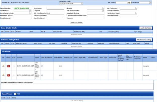
The UTG details are successfully updated. Once you have updated the UTG details, you must add the probe and cable details for the UTG inspection.
 Note: Once you have added UTG details, you can save the added UTG details and reuse the saved details while you adding UTG details for any other UTG report.

- To save the added UTG details, enter any name in the Set Default box and click .
The added details will be saved in the given name.
- If you want to add the same UTG details for any other UTG report, select the name in the Get Default.
The saved details will be automatically updated in the respective boxes.
6.3.2.1 Add Probe & Cable Details
If you want to add probe and cable details for the updated UTG results,
- Click
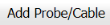 (Add Probe/ Cable button) in the Probe& Cable Details See Fig 6.3.1.
A new window opens to add the probe and cable details.

-
In the Probe box, select a probe from a drop-down list.
-
In the Cable box, select a cable from a drop-down list.
-
In the Ref. dB box, enter the reference decibel range.
-
In the Surf Comp dB box, enter the decibel range of the surface component.
-
In the Test Range (MM) box, enter the test range in millimeters.
-
In the Reference Level box, enter the reference level detail.
-
In the Scanning dB box, enter the scanning decibel range.
-
In the TR Loss box, enter the transmission loss detail.
-
Click Save.

The probe and cable details are successfully added. Once you have added the probe and cable details, you must add the reference setting details.
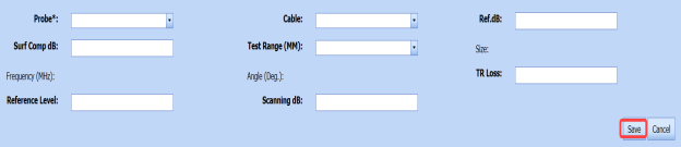
6.3.22 Add Reference Setting Details
If you want to add the reference setting details for the updated UTG results,
-
Click
 (Add Reference Setting button) in the Reference Setting Details window. See Fig 6.3.1.
A new window opens to add the reference setting details.
- In the Reference Block box, select the reference block from a drop-down list.
- In the Probe Sr. No box, select the serial number of the probe from a drop-down list.
- In the Reference box, enter the reference detail.
- In the Eqpt Gain (dB) box, enter the equipment gain in decibels.
- In the Damping box, enter the damping ratio.
- In the Rejection box, enter the rejection detail.
- In the Amplitude Height box, enter the amplitude height range.
- In the Skip box, enter the skip detail.
- In the Beam Path box, enter the beam path detail.
-
In the Range box, enter the range detail.
-
Click Save.


The reference setting details are successfully added. Once you have added the reference setting details, you must add the inspection results for added joints.
6.3.2.3 Add UTG Results
The UTG Results window shows a list of joints added for the UTG inspection. If you want to add UTG results for joints,
- Click
 (Edit icon) for the respective UTG results listed in the UTG Results window.
The UTG Results window opens with the added UTG details.
-
In the Result box, update your UTG inspection results whether Accepted, Rejected, or Cancelled.
-
In the Remarks box, enter your remarks if any.
-
Click Save.


6.3.2.4 Import Additional Joints
If you want to add more joints, you can add by using the import joints option. To import joints,
- Click (Import Joints button) in the UTG Results See Fig 6.3.1.
The Joints window opens with a list of joints.

-
Select the joints you want to import.
-
Click
 (Import Selected Joints button).

The selected joints are imported for the respective UTG and listed in the UTG Results window. Once you have imported the joints, you must add the UTG results for the imported joints.
6.3.2.5 Add Report Photos
If you want to add any report photos for the updated UTG results,
-
Click (ADD button) in the Report Photos box in the UTG Results window. See Fig 6.3.1.

- Click
 (Browse button) to browse a photo stored in your computer.
 -
Click Upload.
The selected photo will be updated.


The UTG results will be updated successfully.
6.3.3 Attach a File into an UTG Report
If you want to attach any file with any UTG report listed in the UTG Report page, you can attach the file by using  (Attach icon) in the Attachment column. To know how to attach, follow the procedures given in the topic “Attach a file into P&ID”.
6.3.4 View an NDT – UTG Report
If you want to print an NDT - UTG report, click  (print icon) provided in the Report column of the UTG Report page. See Fig 6.3.
6.3.5 Edit an UTG Report
If you want to edit any existing UTG report in the UTG Report page, do the following,
- Click (Edit icon) in the Edit column for the respective UTG report. See Fig 6.3.
A new window opens to edit the UTG report.

- Click any box where you want to edit the details, and then edit the details in the respective box.
-
Click Save.

6.3.6 Export UTG Report List
You can export a list of UTG reports added in the UTG Report page in both the pdf and excel formats by using (PDF button) and
  (Excel button). To know how to export, see the topic, “Export P&ID list”.
6.3.7 Filter an UTG Report
If you want to filter any UTG report, do one of the following,

- If you want to filter any UTG report based on the report number, enter the corresponding report number in the Report No box in the UTG Report page, and then Click Search.
-
If you want to filter any UTG report based on the request number, enter the corresponding request number in the Request No box in the UTG Report page, and then Click Search.
- If you want to filter any UTG report based on the drawing number, enter the corresponding drawing number in the Drawing No box in the UTG Report page, and then Click Search.
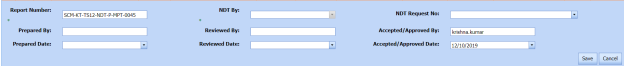
6.4 Dye Penetrant Testing (PT)
Dye Penetrant Testing (DPT) method is one of the oldest and simplest NDT inspection methods used for inspecting the materials in the piping project by using ultraviolet or white light, depending on the type of dye used - fluorescent or non fluorescent (visible). PT also called liquid penetrate inspection (LPI) or penetrant testing (PT).
Once the NDT inspection request is added with the selection of PT type by using the NDT Inspection Request tab, the added inspection request will be moved here. After completing PT inspection, you can add the PT inspection result details by using this PT tab.
-
Click Dye Penetrant Testing (PT) in the Piping menu.
The PT Report page opens.

Figure 6.4: PT Report page
6.4.1 Add a PT Report
If you want to add a PT report, do the following steps,
-
Click
 (ADD button) in the PT Report page. See Fig 6.4.
The PT Report page opens a new window to add an PT report.
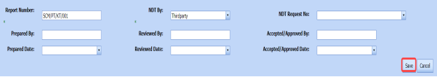
 Note: The fields notified with a symbol (*) are mandatory. You must enter the relevant details in that fields before saving.
 Tip: A report number for a new PT report will be updated automatically in the Report Number box.
 - In the NDT By box, select the requisition detail of NDT whether by third party or internal from a drop-down list.
-
In the NDT Request No box, select an NDT request number from a drop-down list.
-
In the Prepared By box, enter the name of a person who has prepared the PT report.
-
In the Prepared Date box, select the prepared date of the PT report.
-
In the Reviewed By box, enter the name of a person who has reviewed the PT report.
-
In the Reviewed Date box, select the reviewed date of the PT report.
- In the Accepted/Approved By boxes, enter the name of a person who has accepted/approved the PT report.
- In the Accepted/Approved Date box, select the accepted/approved date of the PT report.
-
Click Save.


The PT report is successfully added and listed in the PT Report page. Once you have added the PT report, you must add PT results for the respective added PT report.
6.4.2 Add PT Results
If you want to add the PT results for the respective PT report, do the following steps,
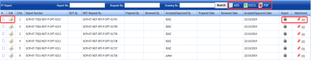
- Click the respective added PT report in the PT Report See Fig 6.4.
The RT Report page shows the DPT Results and Report Photos windows.
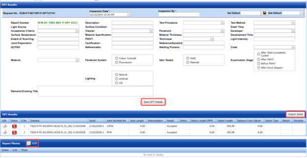
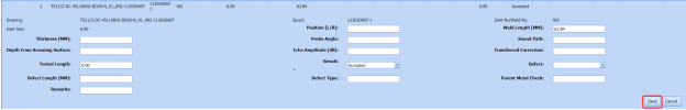
Figure 6.4.1: DPT Results page
- In the Inspection Date box, select the date of DPT inspection.
- In the Inspection By box, enter the name of a person who has done the DPT inspection.
-
In the Light Source box, enter the light source detail.
-
In the Description box, enter the description.
-
In the Test Procedure box, select the test procedure from a drop-down list.
-
In the Test Method box, select the test method from a drop-down list.
-
In the Acceptance Criteria box, select the acceptance criteria from a drop-down list.
-
In the Surface Condition box, enter the condition of the surface.
-
In the Dwell Time box, enter dwell time range.
-
In the Surface Temperature box, enter the surface temperature value.
-
In the Cleaner box, select the cleaner from a drop-down list.
-
In the Penetrant box, select the penetrant from a drop-down list.
-
In the Developer box, select the developer from a drop-down list.
-
In the Material Specification box, enter the material specification.
-
In the Material Thickness box, enter the material thickness value.
-
In the Development Time box, enter the time for development.
-
In the Extend of Scanning box, enter the details of scanning extend.
-
In the PWHT box, enter the PWHT detail.
-
In the Technique box, select the PT technique from a drop-down list.
-
In the Light Intensity box, enter the light intensity value.
-
In the Joint Preparation box, enter the joint preparation detail.
-
In the Certification box, enter the certification detail.
-
In the Reference Standard box, enter the reference standard detail.
-
In the Reference No box, enter the reference number.
-
In the Welding Process box, enter the type of welding process.
-
In the Code box, enter the code detail.
-
In the Examination Stage box, select the examination stage from the specified options.
-
In the Item Tested box, select the tested items from the specified options.
-
In the Inspection Method box, select the inspection method from the specified options.
-
In the Material box, select the material from a drop-down list.
-
In the Penetrant System box, select the type of penetrant system.
-
In the Lighting box, select the type of lighting.
-
In the Remarks/Drawing Title box, enter your remarks if any.
-
Click Save DPT Details.

The DPT details are successfully updated. Once you have updated the DPT details, you must add DPT inspection results for the added joints.
 Note: Once you have added DPT details, you can save the added DPT details and reuse the saved details while you adding DPT details for any other DPT report.

- To save the added DPT details, enter any name in the Set Default box and click .
- If you want to add the same DPT details for any other DPT report, select the name in the Get Default.
The saved details will be automatically updated in the respective boxes.
6.4.2.1 Add PT Results for Joints
The DPT Results window shows a list of joints added for the PT inspection. If you want to add PT results for joints,
- Click
 (Edit icon) for the respective joint listed in the DPT Results window.
The UT Results window opens with the added UT details.
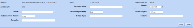
-
In the Result box, update your PT inspection results whether Accepted, Rejected, or Cancelled.
-
In the Remarks box, enter your remarks if any.
-
Click Save.


6.4.2.2 Import Additional Joints
If you want to add more joints, you can add by using the import joints option. To import joints,
-
Click
 (Import Joints button) in the DPT Results window. See Fig 6.4.1.
The Joints window opens with a list of joints.

-
Select the joints you want to import.
- Click
 (Import Selected Joints button).
The selected joints are imported and listed in the DPT Results window. Once you have added joints, you must update the DPT results for added joints.


6.4.2.3 Add Report Photos
If you want to add any report photos for the updated DPT results,
- Click
 (ADD button) in the Report Photos box in the DPT Results See Fig 6.4.1.

-
Click
 (Browse button) to browse a photo stored in your computer.
 -
Click Upload.


The selected photo will be updated.
6.4.3 Attach a File into a PT Report
If you want to attach any file with any PT report listed in the PT Report page, you can attach the file by using  (Attach icon) in the Attachment column. To know how to attach, follow the procedures given in the topic “Attach a file into P&ID”.
6.4.4 View an NDT – PT Report
If you want to view an NDT - PT report, click  (print icon) provided in the Report column of the PT Report page. See Fig 6.4.
6.4.5 Edit a PT Report
If you want to edit any existing PT report in the RT Report page, do the following steps,
- Click
 (Edit icon) in the Edit column for the respective DPT report. See Fig 6.4.
The RT Report page shows the details of the selected PT report.

- Click any box where you want to edit the details, and then edit the details in the respective box.
-
Click Save.

6.4.6 Export PT Report List
You can export a list of RT reports added in the RT Report page in both the pdf and excel formats by using (PDF button) and
  (Excel button). To know how to export, see the topic, “Export P&ID list”.
6.4.7 Filter a PT Report
If you want to filter any PT report, do one of the following,

- If you want to filter any DPT report based on the report number, enter the corresponding report number in the Report No box in the PT Report page, and then Click Search.
- If you want to filter any DPT report based on the request number, enter the corresponding request number in the Request No box in the PT Report page, and then Click Search.
- If you want to filter any DPT report based on the drawing number, enter the corresponding drawing number in the Drawing No box in the PT Report page, and then Click Search.
6.5 Magnetic Particle Testing (MT)
Magnetic Particle Testing also referred to as Magnetic Particle Inspection is one of the NDT inspection methods used to detect defects or discontinuities such as cracks, at or near the surface in ferromagnetic metals such as iron, steel, nickel, cobalt and so on, in the piping project.
Once the NDT inspection request is added with the selection of MT type by using the NDT Inspection Request tab, the added inspection request will be moved here. After completing the MT inspection, you can add the MT inspection result details by using this MT tab.
- Click Magnetic Particle Testing (MT)in the Piping menu.
The MT Report page opens.
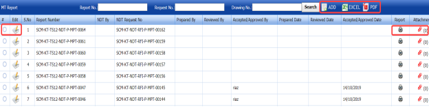
Figure 6.5: MT Report page

6.5.1 Add an MT Report
If you want to add an MT report, do the following steps,
-
Click
 (ADD button) in the MT Report page. See Fig 6.5.
The MT Report page shows a new window opens to add an MT report.
 Note: The fields notified with a symbol (*) are mandatory. You must enter the relevant details in that fields before saving.
 Tip: A report number for a new MT report will be updated automatically in the Report Number box.
 - In the NDT By box, select the requisition detail of NDT inspection whether by third party or internal.
- In the NDT Request No box, select an NDT request number from a drop-down list.
-
In the Prepared By box, enter the name of a person who has prepared the MT report.
- In the Prepared Date box, select the prepared date of the MT report.
- In the Reviewed By box, enter the name of a person who has reviewed the MT request.
- In the Reviewed Date box, select the reviewed date of the MT report.
-
In the Accepted/Approved By boxes, enter the name of a person who has accepted/approved the MT report.
- In the Accepted/Approved Date box, select the accepted/approved date of the MT report.
-
Click Save.


The MT report is successfully added and listed in the MT Report page. Once you have added the MT report, you must add MT results for the respective MT report.
6.5.2 Add MT Results
If you want to add the MT results for the respective MT report, do the following,
- Click the respective MT report in the MT Report page. See Fig 6.5.
The MT Report page shows MPT Results and Report Photos window.

Figure 6.5.1: MT Results page
-
In the Inspection Date box, select the date of inspection.
-
In the Test Equipment box, select the test equipment from a drop-down list.
-
In the Description box, enter the description.
-
In the Test Procedure box, select the test procedure from a drop-down list.
-
In the Test Method box, select the test method from a drop-down list.
-
In the Black Magnetic Ink box, select the type of black magnetic ink from a drop-down list.
-
In the Surface Condition box, enter the condition of the surface.
-
In the Light Source box, enter the light source detail.
-
In the White Contrast Paint box, select the type of white contrast paint.
-
In the Material Specification box, enter the material specification.
-
In the Material Thickness box, enter the material thickness value.
-
In the Type of Current box, enter the type of current.
-
In the Lifting Capacity box, select the lifting capacity value.
-
In the Acceptance Criteria box, select the acceptance criteria from a drop-down list.
-
In the Yoke/ Prod Space box, enter the relevant information.
-
In the Particles Type box, select the type of particles from a drop-down list.
-
In the Particles Make & model box, enter the model of the particle including made of materials.
-
In the Background Contrast & Type box, enter the type of background including contrast range.
- In the Demagnetization box, if you want demagnetization select Yes otherwise select No.
- In the Magnetizing Technique box, enter the magnetizing technique.
-
In the Surface Temperature box, enter the surface temperature value.
-
In the Code box, enter the code detail.
-
In the Color box, select any color from the specified options.
-
In the Suspension box, select any suspension liquid from the specified options.
-
In the Lighting box, select any lighting from the specified options.
-
In the Method box, select any method from the specified options.
-
In the Item Tested box, select the tested items from the specified options.
-
In the Examination Stage box, select the examination stage from the specified options.
-
In the Remarks box, enter your remarks if any.
-
Click Save MPT Details.
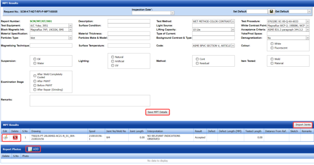
The MT details are successfully updated. Once you have updated the MT details, you must add MT inspection results for the added joints.
 Note: Once you have added MT details, you can save the added MT details and reuse the saved details while you adding MT details for any other MT report.

- To save the added MT details, enter any name in the Set Default box and click.
The added details will be saved in the given name.
-
If you want to add the same MT details for any other MT report, select the name in the Get Default.
The saved details will be automatically updated in the respective boxes.
6.5.2.1 Add MT Results for Joints
The MPT Results window shows a list of joints added for the MT inspection. If you want to add MT results for joints,
- Click
 (Edit icon) for the respective joint listed in the MPT Results window.
The MPT Results window opens a new window with the added MT details.

-
In the Result box, update your MT inspection results whether Accepted, Rejected, or Cancelled.
- In the Remarks box, enter your remarks if any.
-
Click Save.


6.5.2.2 Import Additional joints
If you want to import joints for the updated MPT results,
-
Click
 (Import Joints button) in the MPT Results window. See Fig 6.5.1.
The Joints window opens with a list of joints.

-
Select the joints you want to import.
- Click
 (Import Selected Joints button).
The selected joints are added and listed in the MPT results window. You must add the MT inspection results for the added joints.


6.5.2.3 Add Report Photos
If you want to add any report photos for the updated MT results,
-
Click (ADD button) in the Report Photos box in the MPT Results window. See Fig 6.5.1.

-
Click
 (Browse button) to browse a photo stored in your computer.
 -
Click Upload.


The selected photo will be updated.
6.5.3 Attach a File into an MT Report
If you want to attach any file with any MT report listed in the MT Report page, you can attach the file by using  (Attach icon) in the Attachment column. To know how to attach, follow the procedures given in the topic “Attach a file into P&ID”.
6.5.4 View an NDT – MT Report
If you want to view an NDT - MT report, click  (print icon) provided in the Report column of the MT Report page. See Fig 6.5.
6.5.5 Edit a MT Report
If you want to edit any existing MT report in the MT Report page, do the following steps,
- Click
 (Edit icon) in the Edit column for the respective MT report. See Fig 6.5.
A new window opens to edit the MT report.

-
Click any box where you want to edit the details, and then edit the details in the respective box.
-
Click Save.

6.5.6 Export MT Report List
You can export a list of RT reports added in the RT Report page in both the pdf and excel formats by using  (PDF button) and
  (Excel button). To know how to export, see the topic, “Export P&ID list”.
6.5.7 Filter a MT Report
If you want to filter any MT report, do one of the following,

- If you want to filter any MT report based on the report number, enter the corresponding report number in the Report No box in the MT Report page, and then Click Search.
- If you want to filter any MT report based on the request number, enter the corresponding request number in the Request No box in the MT Report page, and then Click Search.
- If you want to filter any MT report based on the drawing number, enter the corresponding drawing number in the Drawing No box in the MT Report page, and then Click Search.
6.6 Phased Array Ultrasonic Testing (PAUT) Inspection
PAUT is an advanced NDT inspection technique that utilizes multiple UT probes to inspect more complex geometries. PAUT used to inspect almost any material where traditional UT methods have been utilized for weld inspections and crack detection.
The PAUT tab in the Piping menu helps you to add a PAUT report. Once the NDT inspection request is added with the selection of PAUT type by using the NDT Inspection Request tab, the added inspection request will be moved here.
After completing the PAUT inspection, you can add the PAUT inspection result details by using this PAUT tab. To navigate to PAUT,
-
Click PAUT in the Piping menu.
The PAUT Report page opens.


Figure 6.6: PAUT Report page
6.6.1 Add a PAUT Report
If you want to add a PAUT report, do the following steps,
- Click
 (ADD button) in the PAUT Report page. See Fig 6.6.
The PAUT Report page shows a new window to add the details of a PAUT report.
 Note: The fields notified with a symbol (*) are mandatory. You must enter the relevant details in that fields before saving.
 Tip: A report number for a new PAUT report will be updated automatically in the Report Number box. If you want to change the report number, you can change.
 -
In the NDT By box, select the requisition detail of NDT whether by third party or internal.
-
In the NDT Request No box, select an NDT request number from a drop-down list.
-
In the Prepared By box, enter the name of a person who has prepared the PAUT report.
-
In the Prepared Date box, select the prepared date of the PAUT report.
-
In the Reviewed By box, enter the name of a person who has reviewed the PAUT report.
-
In the Reviewed Date box, select the reviewed date of the PAUT report.
- In the Accepted/ Approved By boxes, enter the name of a person who has approved the PAUT report.
-
In the Accepted/ Approved Date box, select the approved date of the PAUT report.
-
Click Save.


The PAUT report is successfully added and listed in the PAUT Report page. Once you have added the PAUT report, you must add PAUT inspection result details.
6.6.2 Add PAUT Inspection Results
If you want to add the PAUT results for the respective PAUT report, do the following steps,
-
Click the respective PAUT report in the PAUT Report page. See Fig 6.6.
The PAUT Report page shows Joint Results, PAUT Results, and Report Photos windows.
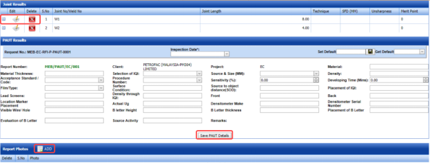
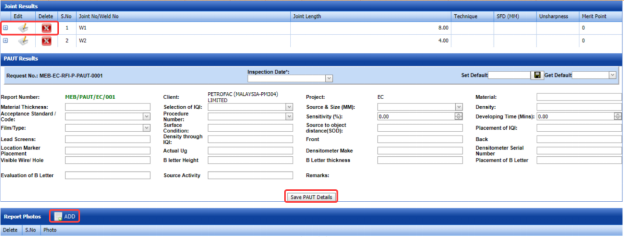
Figure 6.6.1: PAUT Results adding page
-
In the Inspection Date box, select the date of inspection.
-
In the Material Thickness box, enter the thickness of the material.
-
In the Selection of IQI box, select an IQI from a drop-down list.
-
In the Source and Size (MM) box, select a source from a drop-down list.
-
In the Material box, enter the name of the material.
-
In the Density box, enter the density value of the material.
-
In the Acceptance Standard/Code box, select the acceptance standard/code from a drop-down list.
-
In the Procedure Number box, select the procedure number from a drop-down list.
-
In the Sensitivity box, set the sensitivity value of the material.
-
In the Developing Time (Mins) box, set the developing time.
-
In the Film Type box, select the type of film.
-
In the Surface Condition box, enter the surface condition detail.
-
In the Source to Object Distance (SOD) box, enter the distance value from source to object.
-
In the Placement of IQI box, enter the placement detail of IQI.
-
In the Lead Screens box, enter the lead screens detail.
-
In the Density through IQI box, enter the density through IQI detail.
-
In the Front and Back boxes, enter the front and back details.
-
In the Location Marker box, enter the location marker detail.
-
In the Densitometer Serial Number box, enter the densitometer serial number.
-
In the Visible Wire/Hole box, enter the detail of visible wire/hole.
-
In the Remarks box, enter your remarks if any.
-
Click Save PAUT Details.
The PAUT details are successfully updated. Once you have updated the PAUT details, you must add the PAUT inspection results for joints in the Joint Results window.
 Note: Once you have added PAUT details, you can save the added PAUT details and reuse the saved details while you adding PAUT details for any other PAUT report.

- To save the added PAUT details, enter any name in the Set Default box and click .
The added details will be saved in the given name.
- If you want to add the same PAUT details for any other PAUT report, select the name in the Get Default.
The saved details will be automatically updated in the respective boxes.
6.6.2.1 Add PAUT Results for Joints
The Joint Results window shows a list of joints added for the PAUT inspection. If you want to add PAUT results for joints,
- Click
 (Edit icon) for the respective joint listed in the Joint Results window.
The Joint Results window opens a new window with the added joint details.

- In the Result box, update your PWHT inspection results whether Accepted, Rejected, or Cancelled.
-
In the Remarks box, enter your remarks if any.
-
Click Save.


6.6.2.2 Add Report Photos
If you want to add any report photos for the updated PAUT results,
-
Click
 (ADD button) in the Report Photos window. See Fig 6.6.1.
- Click
 (Browse button) to browse a photo stored in your computer.
 -
Click Upload.


The selected photo will be updated.
6.6.3 Attach a File into a PAUT Report
If you want to attach any file with any PAUT report listed in the PAUT Report page, you can attach the file by using  (Attach icon) in the Attachment column. To know how to attach, follow the procedures given in the topic “Attach a file into P&ID”.
6.6.4 View a PAUT Report
If you want to view a PAUT report, click  (print icon) provided in the Report column of the PAUT Report page. See Fig 6.6.
6.6.5 Edit a PAUT Report
If you want to edit any existing PAUT report in the PAUT Report page, do the following,
- Click
 (Edit icon) in the Edit column for the respective PAUT report. See Fig 6.6.
The PAUT Report page shows the details of the added PAUT report.
-
Click any box where you want to edit the details, and then edit the details in the respective box.
-
Click Save.

6.6.6 Export PAUT Report List
You can export a list of PAUT reports added in the PAUT Report page in both the pdf and excel formats by using  (PDF button) and
  (Excel button). To know how to export, see the topic, “Export P&ID list”.
6.6.7 Filter a PAUT Report
If you want to filter any PAUT report,

- If you want to filter any PAUT report based on the report number, enter the corresponding report number in the Report No box in the PAUT Report page, and then Click Search.
- If you want to filter any PAUT report based on the request number, enter the corresponding request number in the Request No box in the PAUT Report page, and then Click Search.
- If you want to filter any PAUT report based on the drawing number, enter the corresponding drawing number in the Drawing No box in the PAUT Report page, and then Click Search.
6.7 Time of Flight Diffraction (TOFD) Inspection
TOFD is a reliable method of NDT- UT used to look for flaws in welds. TOFD uses the time of flight of an ultrasonic pulse to find the location of a reflector. TOFD can also be used for weld overlays in piping.
The TOFD tab in the Piping menu helps you to add a TOFD report. Once the NDT inspection request is added with the selection of TOFD type by using the NDT Inspection Request tab, the added inspection request will be moved here.
After completing the TOFD inspection, you can add the TOFD inspection result details by using this TOFD tab. To navigate to TOFD,
-
Click TOFD in the Piping menu.
The TOFD Report page opens.
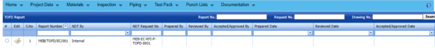

Figure 6.7: TOFD Report page


6.7.1 Add a TOFD Report
If you want to add a TOFD report, do the following steps,
- Click
 (ADD button) in the TOFD Report See Fig 6.7.
The TOFD Report page shows a new window to add the details of a TOFD report.

 Note: The fields notified with a symbol (*) are mandatory. You must enter the relevant details in that fields before saving.
 Tip: A report number for a new TOFD report will be updated automatically in the Report Number box. If you want to change the report number, you can change.
 - In the NDT By box, select the requisition detail of NDT whether by third party or internal.
-
In the NDT Request No box, select an NDT request number from a drop-down list.
-
In the Prepared By box, enter the name of a person who has prepared the TOFD report.
-
In the Prepared Date box, select the prepared date of the TOFD report.
-
In the Reviewed By box, enter the name of a person who has reviewed the TOFD report.
-
In the Reviewed Date box, select the reviewed date of the TOFD report.
-
In the Accepted/ Approved By boxes, enter the name of a person who has approved the TOFD report.
-
In the Accepted/ Approved Date box, select the approved date of the TOFD report.
-
Click Save.

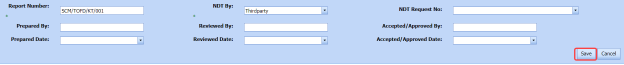


The TOFD report is successfully added and listed in the TOFD Report page. Once you have added the TOFD report, you must add TOFD inspection result details.
6.7.2 Add TOFD Inspection Results
If you want to add the TOFD results for the respective TOFD report, do the following steps,
-
Click the respective TOFD report in the TOFD Report page. See Fig 6.7.
The TOFD Report page shows Joint Results, TOFD Results, and Report Photos windows.
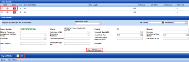
Figure 6.7.1: TOFD Results adding page
-
In the Inspection Date box, select the date of inspection.
-
In the Material Thickness box, enter the thickness of the material.
-
In the Selection of IQI box, select an IQI from a drop-down list.
-
In the Source and Size (MM) box, select a source from a drop-down list.
-
In the Material box, enter the name of the material.
-
In the Density box, enter the density value of the material.
-
In the Acceptance Standard/Code box, select the acceptance standard/code from a drop-down list.
-
In the Procedure Number box, select the procedure number from a drop-down list.
-
In the Sensitivity box, set the sensitivity value of the material.
-
In the Developing Time (Mins) box, set the developing time.
-
In the Film Type box, select the type of film.
-
In the Surface Condition box, enter the surface condition detail.
-
In the Source to Object Distance (SOD) box, enter the distance value from source to object.
-
In the Placement of IQI box, enter the placement detail of IQI.
-
In the Lead Screens box, enter the lead screens detail.
-
In the Density through IQI box, enter the density through IQI detail.
-
In the Remarks box, enter your remarks if any.
-
Click Save TOFD Details.
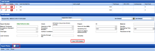
The TOFD details are successfully updated. Once you have updated the TOFD details, you must add the TOFD inspection results for joints in the Joint Results window.
 Note: Once you have added TOFD details, you can save the added TOFD details and reuse the saved details while you adding TOFD details for any other TOFD report.
- To save the added TOFD details, enter any name in the Set Default box and click .
The added details will be saved in the given name.
- If you want to add the same TOFD details for any other TOFD report, select the name in the Get Default.
The saved details will be automatically updated in the respective boxes.
6.7.2.1 Add TOFD Results for Joints
The Joint Results window shows a list of joints added for the TOFD inspection. If you want to add TOFD results for joints,
-
Click
 (Edit icon) for the respective joint listed in the Joint Results window.
The Joint Results window opens a new window with the added joint details.
-
In the Result box, update your PWHT inspection results whether Accepted, Rejected, or Cancelled.
- In the Remarks box, enter your remarks if any.
-
Click Save.


6.7.2.2 Add Report Photos
If you want to add any report photos for the updated TOFD results,
- Click
 (ADD button) in the Report Photos See Fig 6.7.1.

- Click
 (Browse button) to browse a photo stored in your computer.
 -
Click Upload.


The selected photo will be updated.
6.7.3 Attach a File into a TOFD Report
If you want to attach any file with any TOFD report listed in the TOFD Report page, you can attach the file by using  (Attach icon) in the Attachment column. To know how to attach, follow the procedures given in the topic “Attach a file into P&ID”.
6.7.4 View a TOFD Report
If you want to view a TOFD report, click (print icon) provided in the Report column of the PAUT Report page. See Fig 6.7.
6.7.5 Edit a TOFD Report
If you want to edit any existing TOFD report in the TOFD Report page, do the following,
- Click
 (Edit icon) in the Edit column for the respective TOFD report. See Fig 6.7.
The TOFD Report page shows the details of the added TOFD report.
- Click any box where you want to edit the details, and then edit the details in the respective box.
-
Click Save.

6.7.6 Export TOFD Report List
You can export a list of TOFD reports added in the TOFD Report page in both the pdf and excel formats by using  (PDF button) and
  (Excel button). To know how to export, see the topic, “Export P&ID list”.
6.7.7 Filter a TOFD Report
If you want to filter any TOFD report,

- If you want to filter any TOFD report based on the report number, enter the corresponding report number in the Report No box in the TOFD Report page, and then Click Search.
-
If you want to filter any TOFD report based on the request number, enter the corresponding request number in the Request No box in the TOFD Report page, and then Click Search.
- If you want to filter any TOFD report based on the drawing number, enter the corresponding drawing number in the Drawing No box in the TOFD Report page, and then Click Search.
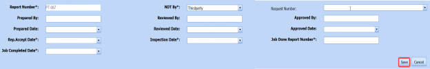
6.8 Post Weld Heat Treatment (PWHT)
The PWHT tab in the Piping menu helps you to add a PWHT report. Once the NDT inspection request is added with the selection of PWHT type by using the NDT Inspection Request tab, the added inspection request will be moved here.
After completing the PWHT inspection, you can add the PWHT inspection result details by using this PWHT tab. To navigate to PWHT,
- Click PWHT in the Piping menu.
The PWHT Report page opens.
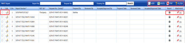
Figure 6.8: PWHT Report page

6.8.1 Add a PWHT Report
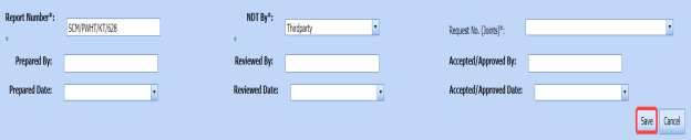
If you want to add a PWHT report, do the following,
- Click
 (ADD button) in the PWHT Report See Fig 6.8.
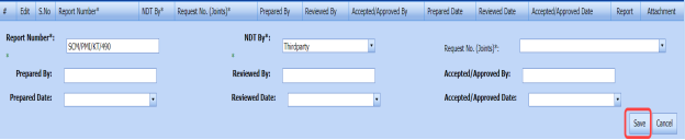
The PWHT Report page shows a new window to add a PWHT report.

 Note: The fields notified with a symbol (*) are mandatory. You must enter the relevant details in that fields before saving.
 Tip: A report number for a new PWHT report will be updated automatically in the Report Number box. If you want to change the report number, you can change.
 - In the NDT By box, select the requisition detail of NDT whether by third party or internal.
- In the Request Number box, select an NDT request number from a drop-down list.
- In the Prepared By box, enter the name of a person who has prepared the PWHT report.
- In the Prepared Date box, select the prepared date of the PWHT report.
- In the Reviewed By box, enter the name of a person who has reviewed the PWHT report.
- In the Reviewed Date box, select the reviewed date of the PWHT report.
- In the Reviewed Date box, select the reviewed date of the PWHT report.
-
In the Accepted/ Approved Date box, select the approved date of the PWHT report.
-
Click Save.


The PWHT report is successfully added and listed in the PWHT Report page. Once you have added the PWHT report, you must add PWHT inspection result details.
6.8.2 Add PWHT Results
If you want to add the PWHT results for the respective PWHT report, do the following steps,
- Click the respective PWHT report in the PWHT Report See Fig 6.8.
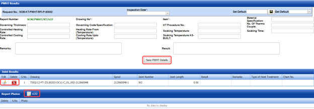
The PWHT Report page shows PWHT Results, Joint Results, and Report Photos windows.
 Figure 9.8.1: PWHT Results page
 -
In the Inspection Date box, select the inspection date.
-
In the Material Specification box, enter the specification for the material.
-
In the Governing Thickness box, enter the governing thickness value.
-
In the Governing Code/Specification box, enter the governing code/specification.
-
In the HT Procedure No box, select the HT procedure number.
-
In the No. of Thermo Couple box, enter the number of thermo couple.
-
In the Controlled Heating Rate box, enter the controlled heating rate value.
-
In the Heating Rate From (Temperature) box, enter the heating rate starting range.
-
In the Soaking Temperature box, enter the soaking temperature value.
-
In the Soaking Time box, enter the soaking time value.
-
In the Controlled Cooling Rate box, enter the range of controlled cooling rate.
-
In the Cooling Rate Up to (Temperature) box, enter the cooling rate temperature range.
-
In the Soaking Temperature box, enter the soaking temperature value.
-
In the Remarks box, enter your remarks if any.
-
In the Result box, enter your PWHT result.
-
Click Save PWHT Details.
The PWHT details are successfully updated. Once you have updated the PWHT details, you must add the PWHT inspection results for joints in the Joint Results window.
 Note: Once you have added PWHT details, you can save the added PWHT details and reuse the saved details while you adding PWHT details for any other PWHT report.

- To save the added PWHT details, enter any name in the Set Default box and click .
The added details will be saved in the given name.
- If you want to add the same PWHT details for any other PWHT report, select the name in the Get Default.
The saved details will be automatically updated in the respective boxes.
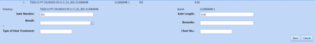
6.8.21 Add PWHT Results for Joints
The Joint Results window shows a list of joints added for the PWHT inspection. If you want to add PWHT results for joints,
- Click
 (Edit icon) for the respective joint listed in the Joint Results window.
The Joint Results window opens a new window with the added joint details.

- In the Result box, update your PWHT inspection results whether Accepted, Rejected, or Cancelled.
-
In the Remarks box, enter your remarks if any.
-
Click Save.


6.8.2.2 Add Report Photos
If you want to add any report photos for the updated PWHT results,
- Click (ADD button) in the Report Photos window. See Fig 6.8.1.

- Click
 (Browse button) to browse a photo stored in your computer.
 -
Click Upload.


The selected photo will be updated.
6.8.3 Attach a File into a PWHT Report
If you want to attach any file with any PWHT report listed in the PWHT Report page, you can attach the file by using  (Attach icon) in the Attachment column. To know how to attach, follow the procedures given in the topic “Attach a file into P&ID”.
6.8.4 View a PWHT Report
If you want to view a PWHT report, click (print icon) provided in the Report column of the PWHT Report page. See Fig 6.8.
6.8.5 Edit a PWHT Report
If you want to edit any existing PWHT report in the PWHT Report page, do the following,
- Click
 (Edit icon) in the Edit column for the respective PWHT report. See Fig 6.8.
The PWHT Report page shows the details of the added PWHT report.
- Click any box where you want to edit the details, and then edit the details in the respective box.
-
Click Save.

6.8.6 Export PWHT Report List
You can export a list of PWHT reports added in the PWHT Report page in both the pdf and excel formats by using  (PDF button) and
  (Excel button). To know how to export, see the topic, “Export P&ID list”.
6.8.7 Filter a PWHT Report
If you want to filter any PWHT report,
- Use
 (FILTER button) in the PWHT Report page, See Fig 6.8. (OR)
 -
Do one of the following steps to filter the PWHT report,

-
-
If you want to filter any PWHT report based on the report number, enter the corresponding report number in the Report No box in the PWHT Report page, and then Click Search.
- If you want to filter any PWHT report based on the request number, enter the corresponding request number in the Request No box in the PWHT Report page, and then Click Search.
- If you want to filter any PWHT report based on the drawing number, enter the corresponding drawing number in the Drawing No box in the PWHT Report page, and then Click Search.
-
-


6.9 Positive Material Identification (PMI)
PMI is one of the more specialized NDT methods. With positive material identification, the alloy composition of materials can be determined.
PMI is one of the more specialized NDT methods. With positive material identification, the alloy composition of materials can be determined.
After completing the PMI inspection, you can add the PMI inspection result details by using this PMI tab. To navigate to PMI,
- Click PMI in the Piping menu.
The PMI Report page opens.
Figure 6.9: PMI Report page

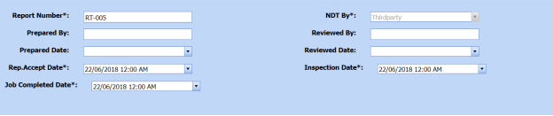
6.9.1 Add a PMI Report
If you want to add a PMI report, do the following,
-
Click
 (ADD button) in the PMI Report page. See Fig 6.9.
The PMI Report page shows a new window to add a new PMI report.
 Note: The fields notified with a symbol (*) are mandatory. You must enter the relevant details in that fields before saving.
 Tip: A report number for a new PMI report will be updated automatically in the Report Number box. If you want to change the report number, you can change.
 - In the NDT By box, select the requisition detail of NDT whether by third party or internal.
- In the Request No box, select an NDT request number from a drop-down list.
- In the Prepared By box, enter the name of a person who has prepared the PMI report.
- In the Prepared Date box, select the prepared date of the PMI report.
- In the Reviewed By box, enter the name of a person who has reviewed the PMI report.
- In the Reviewed Date box, select the reviewed date of the PMI report.
- In the Accepted/ Approved By boxes, enter the name of a person who has approved the PMI report.
- In the Accepted/ Approved Date box, select the approved date of the PMI report.
-
Click Save.


The PMI report is successfully added and listed in the PMI Report page. Once you have added the PMI report, you must add PMI inspection result details.
6.6.2 Add PMI Results
If you want to add the PMI results for the respective PMI report, do the following steps,
- Click the respective PMI report in the PMI Report See Fig 6.9.
The PMI Report page shows PMI Results, PMI Elements, PMI Joint Details, and Report Photos windows.

Figure 9.9.1: PMI Results page
- In the Inspection Date box, select the inspection date.
- In the Test Equipment box, select the test equipment from a drop-down list.
-
In the Material Spec box, select the material specification from a drop-down list.
- In the Text Range box, enter the detail of text range.
- In the Examination Stage box, select the examination stage from the given options.
- Click Save PMI Details.
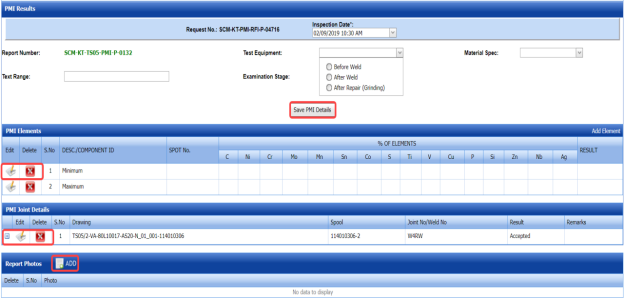
The PMI details are successfully updated. Once you have updated the PMI details, you must add the PMI inspection results for the added elements.
6.9.2.1 Add PMI Results for Elements
The PMI Elements window shows a list of elements added for the PMI inspection. If you want to add PMI results for elements,
- Click
 (Edit icon) for the respective element listed in the PMI Elements window.
The PMI Elements window opens a new window on each column with the added element details.

- Enter the relevant details in each column.
- In the Result column, update your PMI inspection results whether Accepted, Rejected, or Cancelled.
- Click Save.

6.9.2.2 Add More Elements
If you want to add more elements, do the following steps,
- Click Add Element in the PMI Elements window.
A new window opens in each column of the PMI Elements window to add a new element.

-
Enter the relevant details in the respective columns.
-
Click Save.
The element is successfully added.
6.9.2.3 Add PMI Results for Joints
The PMI Joint Details window shows a list of joints added for the PMI inspection. If you want to add PMI results for joints,
- Click
 (Edit icon) for the respective joint listed in the PMI Joint Details window.
The PMI Joint Details window opens a new window with the added joint details.

-
In the Result box, update your PMI inspection results whether Accepted, Rejected, or Cancelled.
- In the Remarks box, enter your remarks if any.
- Click Save.

6.9.2.4 Add Report Photos
If you want to add any report photos for the updated PMI results,
- Click
 (ADD button) in the Report Photos window. See Fig 6.9.1.

- Click
 (Browse button) to browse a photo stored in your computer.
 -
Click Upload.
The selected photo will be updated.


6.9.3 Attach a File into a PMI Report
If you want to attach any file with any PMI report listed in the PMI Report page, you can attach the file by using  (Attach icon) in the Attachment column. To know how to attach, follow the procedures given in the topic “Attach a file into P&ID”.
6.9.4 View a PMI Report
If you want to view a PMI report, click  (print icon) provided in the Report column of the PMI Report page. See Fig 6.9.
6.9.5 Edit a PMI Report
If you want to edit any existing PMI report in the PMI Report page, do the following,
- Click
 (Edit icon) in the Edit column for the respective PMI report. See Fig 6.9.
The PMI Report page shows the details of the added PMI report.
- Click any box where you want to edit the details, and then edit the details in the respective box.
-
Click Save.

6.9.6 Export PMI Report List
You can export a list of PMI reports added in the PMI Report page in both the pdf and excel formats by using  (PDF button) and
  (Excel button). To know how to export, see the topic, “Export P&ID list”.
6.9.7 Filter a PMI Report
If you want to filter any PMI report,
- Use
 (FILTER button) in the PMI Report page, See Fig 6.9. (OR)
 -
Do one of the following steps to filter the PMI report,

-
- If you want to filter any PMI report based on the report number, enter the corresponding report number in the Report No box in the PMI Report page, and then Click Search.
- If you want to filter any PMI report based on the request number, enter the corresponding request number in the Request No box in the PMI Report page, and then Click Search.
- If you want to filter any PMI report based on the drawing number, enter the corresponding drawing number in the Drawing No box in the PMI Report page, and then Click Search.
-


6.10 Ferrite
Ferrite testing, also referred to as a ferrite scope test, is a rapid NDT method used to measure the amount of delta ferrite on materials used in the piping project.
The Ferrite tab in the Piping menu helps you to add a ferrite report. Once the NDT inspection request is added with the selection of ferrite type by using the NDT Inspection Request tab, the added inspection request will be moved here.
The Ferrite tab in the Piping menu helps you to add a ferrite report. Once the NDT inspection request is added with the selection of ferrite type by using the NDT Inspection Request tab, the added inspection request will be moved here.
- Click Ferrite in the Piping menu.
The Ferrite Report page opens.

Figure 6.10: Ferrite Report page

6.10.1 Add a Ferrite Report
If you want to add a ferrite report, do the following steps,
- Click
 (ADD button) in the Ferrite Report page. See Fig 6.10.
The Ferrite Report page shows a new window to add a new ferrite report.
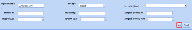
 Note: The fields notified with a symbol (*) are mandatory. You must enter the relevant details in that fields before saving.
 Tip: The report number for a new ferrite report will be updated automatically in the Report Number box. If you want to change the report number, you can change.
 - In the NDT By box, select the requisition detail of NDT whether by third party or internal.
- In the Request No box, select an NDT request number from a drop-down list.
-
In the Prepared By box, enter the name of a person who has prepared the ferrite report.
-
In the Prepared Date box, select the prepared date of the ferrite report.
-
In the Reviewed By box, enter the name of a person who has reviewed the ferrite report.
-
In the Reviewed Date box, select the reviewed date of the ferrite report.
- In the Accepted/ Approved By boxes, enter the name of a person who has approved the ferrite report.
- In the Accepted/ Approved Date box, select the approved date of the PMI report.
- Click Save.
The ferrite report is successfully added and listed in the Ferrite Report page. Once you have added the ferrite report, you must add ferrite inspection result details.


6.10.2 Add Ferrite Inspection Results
If you want to add ferrite inspection results for the respective ferrite report, do the following steps,
- Click the respective ferrite report in the Ferrite Report See Fig 6.10.
The Ferrite Report page shows Ferrite Results, Ferrite Inspection Details, Joint Results, and Report Photos windows.
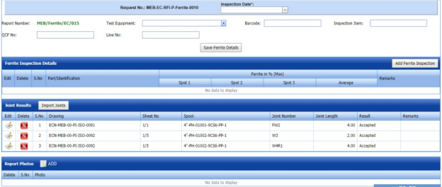
Figure 6.10.1: Ferrite Results page
- In the Inspection Date box, select the date of ferrite inspection.
-
In the Test Equipment box, select the test equipment from a drop-down list.
-
In the Barcode box, enter the barcode of the material.
-
In the Inspection Item box, enter the detail of inspection items.
-
In the QCF No box, enter the QCF number.
-
In the Line No box, enter the line number.
-
Click Save Ferrite Details.

The ferrite details are successfully updated. Once you have updated the ferrite details, you must add the ferrite inspection results.
6.10.2.1 Add Ferrite Inspection Details
If you want to add ferrite inspection details,
-
Click Add Ferrite Inspection in the Ferrite Inspection Details window.
The Ferrite Inspection Details window opens a new window on each column.

-
Enter the relevant details in each column.
-
Click Save.

6.10.2.2 Add Joint Results
The Joint Results window shows a list of joints added for the ferrite inspection. If you want to add ferrite inspection results for joints,
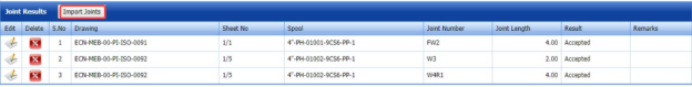
- Click
 (Edit icon) for the respective joint listed in the Joint Results window.
The Joint Results window opens a new window with the added joint details.
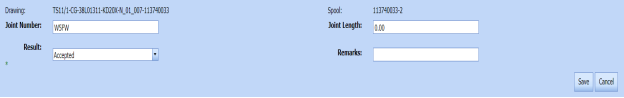
- In the Result box, update your ferrite inspection results whether Accepted, Rejected, or Cancelled.
- In the Remarks box, enter your remarks if any.
-
Click Save.


6.10.2.3 Import Joints
If you want to import multiple joints,
- Click (Import Joints button) in the Joint Results window.
The Joints window opens.

- Select the checkbox of the joints you want to import.
-
Click Import Selected Joints.
The imported joints will be listed in the Joint Results window.
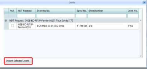
6.10.2.4 Add Report Photos
If you want to add any report photos for the updated ferrite inspection results,
- Click
 (ADD button) in the Report Photos window.

- Click
 (Browse button) to browse a photo stored in your computer.
 -
Click Upload.
The selected photo will be updated.


6.10.3 Attach a File into a Ferrite Report
If you want to attach any file with any ferrite report listed in the Ferrite Report page, you can attach the file by using  (Attach icon) in the Attachment column. To know how to attach, follow the procedures given in the topic “Attach a file into P&ID”.
6.10.4 View a Ferrite Report
If you want to view a ferrite report, click (print icon) provided in the Report column of the Ferrite Report page. See Fig 6.10.
6.10.5 Edit a Ferrite Report
If you want to edit any existing ferrite report in the Ferrite Report page, do the following steps,
- Click
 (Edit icon) in the Edit column for the respective ferrite report. See Fig 6.10.
The Ferrite Report page shows the details of the added ferrite report.
- Click any box where you want to edit the details, and then edit the details in the respective box.
- Click Save.

6.10.6 Export Ferrite Report List
You can export a list of ferrite reports added in the Ferrite Report page in both the pdf and excel formats by using  (PDF button) and
  (Excel button). To know how to export, see the topic, “Export P&ID list”.
6.10.7 Filter a Ferrite Report
If you want to filter any ferrite report,
- Use (FILTER button) in the Ferrite Report page, See Fig 9.10. (OR)
-
Do one of the following steps to filter the ferrite report,

-
-
If you want to filter any ferrite report based on the report number, enter the corresponding report number in the Report No box in the Ferrite Report page, and then Click Search.
- If you want to filter any ferrite report based on the request number, enter the corresponding request number in the Request No box in the Ferrite Report page, and then Click Search.
- If you want to filter any ferrite report based on the drawing number, enter the corresponding drawing number in the Drawing No box in the Ferrite Report page, and then Click Search.
-
-

6.11 Hardness
Harness testing is one of the NDT type of inspection. Hardness testing is performed to evaluate the mechanical properties metal joints and other materials thus helps to ensure that the material meets a particular specification.
The Hardness tab in the Piping menu helps you to add a hardness report. Once the NDT inspection request is added with the selection of hardness type testing by using the NDT Inspection Request tab, the added inspection request will be moved here.
After completing the hardness testing, you can add the hardness testing result details by using this Hardness tab. To navigate to Hardness,
- Click Hardness in the Piping menu.
The Hardness Report page opens.
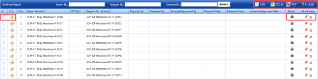
Figure 6.11: Hardness Report page

6.11.1 Add a Hardness Report
If you want to add a hardness report, do the following steps,
- Click
 (ADD button) in the Hardness Report See Fig 6.11.
The Hardness Report page shows a new window to add a new hardness report.
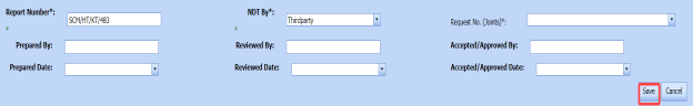
 Note: The fields notified with a symbol (*) are mandatory. You must enter the relevant details in that fields before saving.
 Tip: A report number for a new hardness report will be updated automatically in the Report Number box. If you want to change the report number, you can change.
 - In the NDT By box, select the requisition detail of NDT whether by third party or internal.
-
In the Request No box, select an NDT request number from a drop-down list.
-
In the Prepared By box, enter the name of a person who has prepared the hardness report.
-
In the Prepared Date box, select the prepared date of the hardness report.
-
In the Reviewed By box, enter the name of a person who has reviewed the hardness report.
-
In the Reviewed Date box, select the reviewed date of the hardness report.
- In the Accepted/ Approved By boxes, enter the name of a person who has approved the hardness report.
- In the Accepted/ Approved Date box, select the approved date of the hardness report.
-
Click Save.


The hardness report is successfully added and listed in the Hardness Report page. Once you have added the hardness report, you must add hardness testing result details.
6.11.2 Add Harness Results
If you want to add the hardness testing results for the respective Hardness report, do the following steps,
- Click the respective hardness report in the Hardness Report See Fig 6.11.
The Hardness Report page shows Hardness Results, Joint Results, and Report Photos windows.

Figure 6.11.1: Hardness Results page
-
In the Inspection Date box, select the date of hardness testing.
- In the Part Description box, enter the description of a part to be tested for hardness.
-
In the Weld Map No box, enter the weld map drawing number.
-
In the Material Spec & Grade box, enter the grade and description for the material.
-
In the Instrument box, enter the name of the instrument to be used for hardness testing.
-
In the Instrument Make/ Model/ SL. No. box, enter the instrument model or serial number.
-
In the Intender Type box, enter the type of intender.
-
In the Result box, enter the result of hardness test.
-
In the Procedure No box, select the procedure number from a drop-down list.
-
In the Remarks box, enter your remarks if any.
-
Click Save Hardness Details.
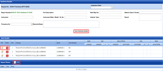
The hardness details are successfully updated. Once you have updated the hardness details, you must add the hardness inspection results for the joints.
6.11.2.1 Add Hardness Testing Results of joints
The Joint Results window shows a list of joints added for the hardness test. If you want to add hardness test results for joints,
- Click
 (Edit icon) for the respective joint listed in the Joint Results window.
The Joint Results window opens a new window for each column with the added joint details.

-
Update your hardness test details in all columns.
-
Click Save.

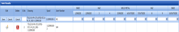
6.11.2.2 Add Report Photos
If you want to add any report photos for the updated hardness test results,
- Click
 (ADD button) in the Report Photos window.

-
Click
 (Browse button) to browse a photo stored in your computer.
 -
Click Upload.
The selected photo will be updated.


6.11.3 Attach a File into a Hardness Report
If you want to attach any file with any hardness report listed in the Hardness Report page, you can attach the file by using (Attach icon) in the Attachment column. To know how to attach, follow the procedures given in the topic “Attach a file into P&ID”.
6.11.4 View a Hardness Report
If you want to view a hardness report, click (print icon) provided in the Report column of the Hardness Report page. See Fig 6.11.
6.11.5 Edit a Hardness Report
If you want to edit any existing hardness report in the Hardness Report page, do the following steps,
- Click
 (Edit icon) in the Edit column for the respective hardness report. See Fig 6.11.
The Hardness Report page shows the details of the added hardness report.
-
Click any box where you want to edit the details, and then edit the details in the respective box.
-
Click Save.

6.11.6 Export Hardness Report List
You can export a list of hardness reports added in the Hardness Report page in both the pdf and excel formats by using  (PDF button) and
  (Excel button). To know how to export, see the topic, “Export P&ID list”.
6.11.7 Filter a Hardness Report
If you want to filter any hardness report,
- Use
 (FILTER button) in the Hardness Report page, See Fig 6.11. (OR)
 - Do one of the following steps to filter the hardness report,

-
- If you want to filter any hardness report based on the report number, enter the corresponding report number in the Report No box in the Hardness Report page, and then Click Search.
- If you want to filter any hardness report based on the request number, enter the corresponding request number in the Request No box in the Hardness Report page, and then Click Search.
-
If you want to filter any hardness report based on the drawing number, enter the corresponding drawing number in the Drawing No box in the Hardness Report page, and then Click Search.
-


6.12 RFI Hydro Pressure Report
The RFI Hydro Pressure Report tab in the Piping menu helps you to add a hydro pressure report in piping project. To navigate to RFI Hydro Pressure Report,
- Click RFI Hydro Pressure Report in the Piping menu.
The Pressure Report page opens.
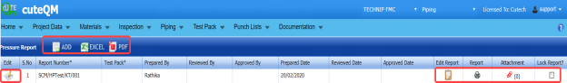
Figure 6.12: Pressure Report page

6.12.1 Add a Hydro Pressure Report
If you want to add a hydro pressure report, do the following steps,
- Click
 (ADD button) in the Pressure Report page. See Fig 6.12.
The Pressure Report page shows a new window to add details of a new hydro pressure report.

 Note: The fields notified with a symbol (*) are mandatory. You must enter the relevant details in that fields before saving.
 Tip: A report number for a new hydro pressure report will be updated automatically in the Report Number box. If you want to change the report number, you can change.
 -
In the Test Pack box, select the test pack from a drop-down list.
-
In the Prepared By box, enter the name of a person who has prepared the hydro pressure report.
-
In the Prepared Date box, select the prepared date of the hydro pressure report.
-
In the Reviewed By box, enter the name of a person who has reviewed the hydro pressure report.
-
In the Reviewed Date box, select the reviewed date of the hydro pressure report.
- In the Approved By boxes, enter the name of a person who has approved the hydro pressure report.
- In the Approved Date box, select the approved date of the hydro pressure report.
-
Click Save.

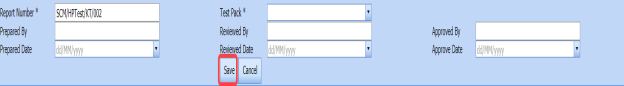


The hydro pressure report is successfully added and listed in the Pressure Report page. Once you have added the hydro pressure report, you must add hydro pressure test details.
6.12.2 Add Hydro Pressure Test Details
If you want to add the hydro pressure test details, do the following steps,
- Click
 (Edit icon) in the Edit Report column of the Pressure Report page. See Fig 6.12.
The Pressure Report page shows Test Parameters, Equipment Details, and Pressure Raise & Reduce Records windows.
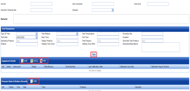
Figure 6.12.1: Pressure Report page
-
In the Unit No box, enter the unit number.
-
In the Sub Contractor box, enter the name of a sub-contractor.
-
In the Test Zone box, enter the detail of test zone.
-
In the Isometric Drawing No box, enter the isometric drawing number.
-
In the Decision box, select your decision whether confirm or non-confirm.
-
In the Remarks box, enter your remarks if any.


6.12.2.1 Add Test Parameters
If you want to add test parameters for the hydro pressure test, enter the following details in the Test Parameters window,
- In the Type of Test box, select the test type from a drop-down list.
-
In the Test Medium box, select the test medium from a drop-down list.
-
In the Test Temperature box, enter the test temperature value.
-
In the Procedure No box, enter the procedure number.
-
In the Test Date box, select the test date.
-
In the Start Time and End Time boxes, enter the start time and end time of test.
-
In the Duration box, enter the duration of test.
-
In the Operating Pressure box, enter the operating pressure value.
- In the Design Pressure box, enter the design pressure value.
-
In the Recorded Test Pressure box, enter the recorded test pressure value.
-
In the Position box, enter the position detail.
-
In the Holding Time (Hrs) box, enter the holding period in hours.
-
In the Holding Time (Min) box, enter the holding period in minutes.
-
In the Remarks/Observations box, enter your remarks/observations if any.
-
Click Save.
6.12.2.2 Add Equipment Details
If you want to add equipment details for the hydro pressure test,
- Click (ADD button) in the Equipment Details window.

- In the Conducted By box, select the method of conducting hydro pressure test whether Internal or
- In the Equipment Details box, select an equipment from a drop-down list.
-
Click Save.
The equipment is successfully added and listed in the Equipment Details window. Once you have added the equipment, you must add the calibration detail for the added equipment.
-
To add calibration detail, click
 (Edit icon) in the Edit column for the equipment.
The Equipment Details windows shows a new window with added equipment details.
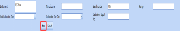
-
In the Manufacturer box, enter the name of the manufacturer.
-
In the Last Calibration Date box, select the last calibration date.
-
In the Calibration Due Date box, select the calibration due date.
-
In the Calibration Report No box, enter the calibration report number.
-
Click Save.
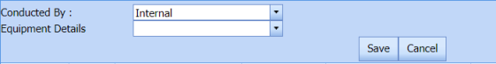

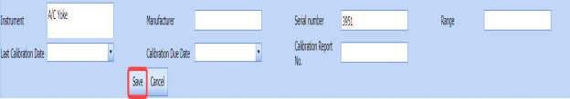
6.12.2.3 Add Pressure Raise and Reduce Records
If you want to add pressure raise and reduce records,
- Click
 (ADD button) in the Pressure Raise & Reduce Records window.
The Pressure Raise & Reduce Records window opens a new window to add the required details.
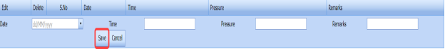
- In the Date box, select the pressure testing date.
-
In the Time box, enter the time of pressure testing.
-
In the Pressure box, enter the pressure value.
-
In the Remarks box, enter your remarks if any.
-
Click Save.


6.12.3 Attach a File into a Hydro Pressure report
If you want to attach any file with any hydro pressure report listed in the Pressure Report page, you can attach the file by using  (Attach icon) in the Attachment column. To know how to attach, follow the procedures given in the topic “Attach a file into P&ID”.
6.12.4 View a Hydro Pressure Report
If you want to view a hydro pressure report, click (print icon) provided in the Report column of the Pressure Report page. See Fig 6.12.
6.12.5 Edit a Hydro Pressure Report
If you want to edit any existing hydro pressure report in the Pressure Report page, do the following steps,
-
Click
 (Edit icon) in the Edit column for the respective hydro pressure report. See Fig 6.12.
The Pressure Report page shows the details of the added pressure report.
- Click any box where you want to edit the details, and then edit the details in the respective box.
-
Click Save.

6.12.6 Export Hydro Pressure Report List
You can export a list of hydro pressure reports added in the Pressure Report page in both the pdf and excel formats by using (PDF button) and
  (Excel button). To know how to export, see the topic, “Export P&ID list”.
6.12.7 Lock a Hydro Pressure Report
If you want to lock any hydro pressure report, select the checkbox of the respective hydro pressure report. See Fig 6.12.
6.13 PMI/Hardness Summary Report
The PMI/HARDNESS Summary Report tab in the Piping menu helps you to view the PMI and hardness summary report. To view the report,
- Click PMI/HARDNESS Summary Report in the Piping menu.
The PMI and Hardness summary report page opens.

Figure 6.13: PMI/Hardness Summary Report page
- If you want to view the PMI summary report, click the PMI option.
The PMI Summary Report opens.
- If you want to view the hardness summary report, click the HARDNESS option.
The Hardness Summary Report opens.
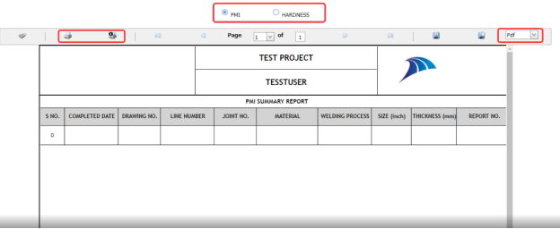
6.13.1 Print a PMI and Hardness Summary Report
If you want to print a PMI/Hardness summary report, use  and
and  (print icons) provided in the PMI and Hardness summary report page.
- If you want to print the current page of the PMI and Hardness summary report, click
 (print icon including the page number).
 -
If you want to print all the pages of the PMI and Hardness summary report, click
 (print icon).


6.13.2 View a PMI and Hardness Summary Report
You can view the PMI and Hardness summary report in various formats by using the option  provided in the upper right corner of the PMI and Hardness summary report page.
6.14 Preheat/PWHT Summary Report
The PREHEAT/PWHT Summary Report tab in the Piping menu helps you to view the Preheat and PWHT summary report. To view the report,
- Click PREHEAT/PWHT Summary Report in the Piping menu.
The Preheat and PWHT summary report page opens.
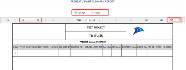
Figure 6.14: Preheat/PWHT Summary Report page
- If you want to view the preheat summary report, click the PREHEAT option.
The Preheat Summary Report opens.
-
If you want to view the PWHT summary report, click the PWHT option.
The PWHT Summary Report opens.

6.14.1 Print a Preheat and PWHT Summary Report
If you want to print a Preheat/PWHT summary report, use  and
and  (print icons) provided in the Preheat and PWHT summary report page.
- If you want to print the current page of the Preheat and PWHT summary report, click
 (print icon including the page number).
 -
If you want to print all the pages of the Preheat and PWHT summary report, click
 (print icon).


6.14.2 View a Preheat and PWHT Summary Report
You can view the preheat and PWHT summary report in various formats by using the option  provided in the upper right corner of the Preheat and PWHT summary report page.
6.15 PAUT Summary Report
The PAUT Summary Report tab in the Piping menu helps you to view the PAUT summary report. To view the report,
- Click PAUT Summary Report in the Piping menu.
The PAUT summary report page opens.
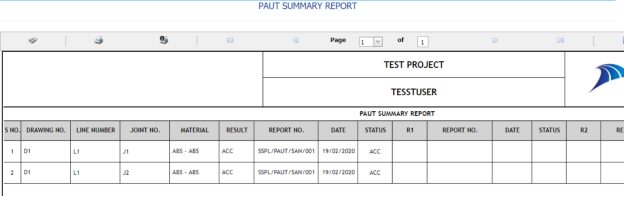
Figure 6.15: PAUT Summary Report page

6.15.1 Print a PAUT Summary Report
If you want to print a PAUT summary report, use  and
and  (print icons) provided in the PAUT summary report page.
- If you want to print the current page of the PAUT summary report, click
 (print icon including the page number).
 - If you want to print all the pages of the PAUT summary report, click
 (print icon).


6.15.2 View a PAUT Summary Report
You can view the PAUT summary report in various formats by using the option  provided in the upper right corner of the PAUT summary report page.
6.16 RT Summary Report
The RT Summary Report tab in the Piping menu helps you to view the RT summary report. To view the report,
- Click RT Summary Report in the Piping menu.
The RT summary report page opens.
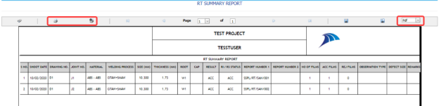
Figure 6.16: RT Summary Report page

6.16.1 Print a RT Summary Report
If you want to print a RT summary report, use  and
and  (print icons) provided in the RT summary report page.
- If you want to print the current page of the RT summary report, click
 (print icon including the page number).
 -
If you want to print all the pages of the RT summary report, click
 (print icon).


6.16.2 View a RT Summary Report
You can view the RT summary report in various formats by using the option  provided in the upper right corner of the RT summary report page.
6.17 Welder Performance Record
The Welder Performance Record tab in the Piping menu helps you to view a performance record of welders. To view the welder performance record,
- Click Welder Performance Record in the Piping menu.
The Welder Performance Record page opens.

Figure 6.17: Welder Performance Record page
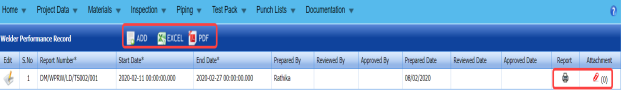
6.17.1 Add a Welder Performance Record
If you want to add a welder performance record, do the following steps,
- Click
 (ADD button) in the Welder Performance Record page.
The page opens a new window to add the details of the welder performance record.
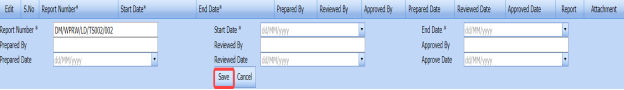
 Tip: The report number for the welder performance record will be updated automatically. If you want to change the report number, you can change.
 - In the Start Date and End Date boxes, select the start and ending dates to view the welder performance record.
-
In the Prepared By box, enter the name a person who has prepared the welder performance record.
- In the Prepared Date box, enter the prepared date of the welder performance record.
-
In the Reviewed By box, enter the name a person who has reviewed the welder performance record.
-
In the Reviewed By box, enter the name a person who has reviewed the welder performance record.
-
In the Approved By box, enter the name a person who has approved the welder performance record.
- In the Approved Date box, enter the approved date of the welder performance record.
- Click Save.
The welder performance record will be added and listed in the Welder Performance Record page.


6.17.2 Edit a Welder Performance Record
If you want to edit any existing welder performance record in the Welder Performance Record page, do the following steps,
- Click
 (Edit icon) in the Edit column for the respective welder performance record. See Fig 6.17.
The Welder Performance Record page shows the details of the added welder performance record.
-
Click any box where you want to edit the details, and then edit the details in the respective box.
- Click Save.

6.17.3 View a Welder Performance Record
If you want to view a welder performance record, click (print icon) provided in the Welder Performance Record page. See Fig 6.17.
6.17.4 Attach a File into a Welder Performance Record
If you want to attach any file with a welder performance record listed in the Welder Performance Record page, you can attach the file by using  (Attach icon) in the Attachment column. To know how to attach, follow the procedures given in the topic “Attach a file into P&ID”.
6.17.5 Export a Welder Performance Record
You can export the welder performance in the Welder Performance Record page in both the pdf and excel formats by using (PDF button) and
  (Excel button). To know how to export, see the topic, “Export P&ID list”.
6.18 Generate Weld Visual Report
The Generate Weld Visual Report tab in the Piping menu helps you to generate a weld visual report.
- Click Generate Weld Visual Report in the Piping menu.
The Daily Pipe Weld Visual Record page opens.
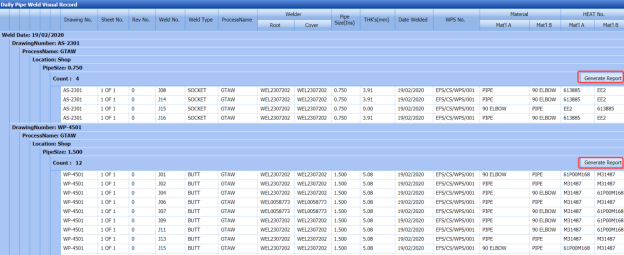
Figure 6.18: Daily Pipe Weld Visual Record page
The Daily Pipe Weld Visual Record page shows the list of weld visual inspections completed on each day including the welding date, weld process name, location, pipe size, and drawing name.
-
-
The Daily Pipe Weld Visual Record page shows the list of weld visual inspections completed on each day including the welding date, weld process name, location, pipe size, and drawing name.
- Each group has a maximum of 20 number of weld visual inspection.
- Each group is separated by different group number.
- You can generate a report for each group individually by using the respective report generating option provided in the Daily Pipe Weld Visual Record page.
-
-
- If you want to generate report of DPWR for any group or date, click
 (Generate Report button) of the respective group or date.

The generated reports will be moved to the Weld Visual Report page. To view the generated reports, navigate to the Weld Visual Report tab.
6.19 Weld Visual Report
The Weld Visual Report tab in the Piping menu helps you to view a weld visual report. Once you have generated the weld visual report, the generated report will be moved here. You can view the respective report by using this tab. To view the weld visual report,
- Click Weld Visual Report in the Piping menu.
The Weld Visual Report page opens.

Figure 6.19: Weld Visual Report page
 Note: If you want to view the welded joints, select the checkbox of the Show Welded Joints option provided in the page. The page shows the list of welded joints.
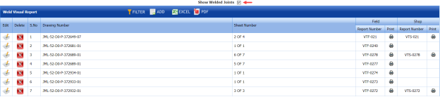

6.19.1 Add Weld Visual Report
If you want to add a weld visual report, do the following steps,
- Click
 (ADD button) in the Weld Visual Report page.
The page opens a new window to add the details of the weld visual report.
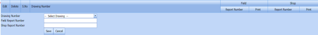
-
In the Drawing Number box, select the drawing number from a drop-down list.
The field report number and shop report number will be updated automatically in the respective boxes.
-
Click Save.
The weld visual report is successfully added and listed in the Weld Visual Report page.


6.19.2 Edit a Weld Visual Report
If you want to edit any existing weld visual report in the Weld Visual Report page, do the following steps,
- Click
 (Edit icon) in the Edit column for the respective weld visual report. See Fig 6.19.
The Weld Visual Report page shows the details of the added report.
- Click any box where you want to edit the details, and then edit the details in the respective box.
-
Click Save.

6.19.3 Delete a Weld Visual Report
If you want to delete any weld visual report in the Weld Visual Report page, you can use  (Delete icon) provided in the Weld Visual Report page. To know how to delete, see the topic, “Delete P&ID”.
6.19.4 View a Weld Visual Report
- If you want to view a weld visual report related with the field inspection, click
 (print icon) provided in the Field column. See Fig 6.19.
 - If you want to view a weld visual report related with the shop inspection, click
 (print icon) provided in the Shop See Fig 6.19.


6.19.5 Filter a Weld Visual Report
If you want to filter any weld visual report in the Weld Visual Report page, you can use  (FILTER button) located on the Weld Visual Report page. To know how to filter, see the topic, “Filter P&ID”.
6.19.6 Export a Weld Visual Report
You can export the weld visual reports in the Weld Visual Report page in both the pdf and excel formats by using (PDF button) and (Excel button). To know how to export, see the topic, “Export P&ID list”.
6.20 Weld Joint Log Sheet
The Weld Joint Log sheet tab in the Piping menu helps you to view a log sheet of pipe welding inspection. To view the log sheet,
- Click Weld Joint Log sheet in the Piping menu.
The pipe welding inspection log sheet page opens.
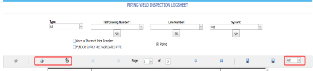
Figure 6.20: Pipe welding inspection log sheet page
-
In the Type box, select the type of joint.
-
Do one of the following steps,
-
- In the ISO Drawing Number box, select the isometric drawing number from a drop-down list.
-
In the Line Number box, select the line number from a drop-down list.
-
In the System box, select the system from a drop-down list.
-
-
Click Go.
- If you want to open the log sheet in a threaded joint template, click the checkbox of the Open in Threaded Joint Template option.
- If you want to open the log sheet in a threaded joint template, click the checkbox of the Open in Threaded Joint Template option.
The pipe welding inspection log sheet opens for the selected option.


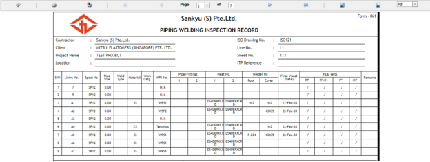
6.20.1 Print a Weld Joint Log sheet
If you want to print the weld joint log sheet, use  and
and  (print icons) provided in the Weld Joint Log sheet page.
- If you want to print the current page of the Weld Joint Log sheet, click
 (print icon including the page number).
 - If you want to print all the pages of the Weld Joint Log sheet, click
 (print icon).


6.20.2 View a Weld Joint Log sheet
You can view the weld joint log sheet in various formats by using the option provided in the upper right corner of the Weld Joint Log sheet page.
6.21 Joint Summary Report
The Joint Summary report tab in the Piping menu used to view a joint summary report. If you want to see a joint summary report,
-
Click Joint Summary Report in the Piping menu.
The Joint Summary Report page shows summary details of isometric drawing, joints, welders, components and so on.
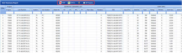
Figure 9.21: Joint Summary Report page

6.21.1 Export a Joint Summary Report
You can export the joint summary report in both the pdf and excel formats by using  (PDF button) and
  (Excel button) in the Joint Summary Report page. To know how to export, see the topic, “Export P&ID list”.
6.21.2 View a Joint Summary Report
If you want to view a joint summary report, click (print icon) provided in the Joint Summary Report page. See Fig 6.21.
6.22 Welding Application Report
The Welding Application Report tab in the Piping menu shows a welding application report.
If you want to view a welding application report,
- Click Welding Application Report in the Piping menu.
The welding application report page opens with the details of welding application.
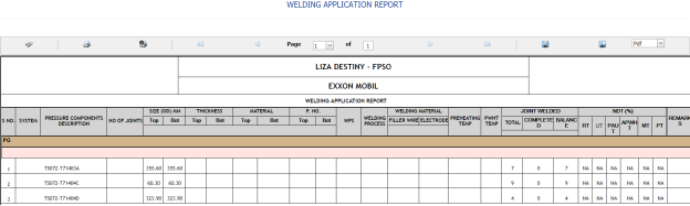
Figure 6.22: Welding Application Report page

6.22.1 Print a Welding Application Report
If you want to print a welding application report, use  and
and  (print icons) provided in the Welding Application Report page. See Fig 6.22.
- If you want to print the current page of the welding application report, click
 (print icon including the page number).
 - If you want to print all the pages of the welding application report, click
 (print icon).


6.22.2 Export a Welding Application Report
You can export the welding application report in various formats by using the option  provided in the upper right corner of the Welding Application Report page.
6.23 Weld Rejection Rate
Weld Rejection Rate is the difference between the tested length and repair length of the welded material, which are calculated using RT and UT inspection. The Weld Rejection Rate is used to calculate the weld success rate.
The Weld Rejection Rate tab in the Piping menu shows a weld rejection rate report including weekly and cumulative weld success rate summary details.
If you want to view a weld rejection rate report,
- Click Weld Rejection Rate in the Piping menu.
The weld rejection rate report page opens.
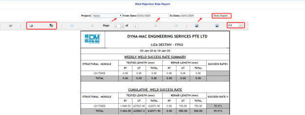
Figure 6.23: Weld Rejection Rate Report page
- In the Project box, select a project for which you want to view a weld rejection rate report, from a drop-down list.
-
In the From Date and To Date boxes, select the from and to dates in respectively.
-
Click Show Report.
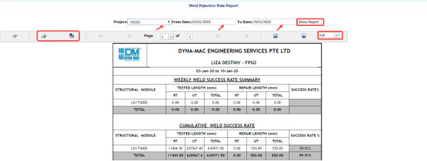
The weld rejection rate report opens for the selected project.
6.23.1 Print a Weld Rejection Rate Report
If you want to print a weld rejection rate report, use  and
and  (print icons) provided in the Weld Rejection Rate Report page. See Fig 6.23.
- If you want to print the current page of the weld rejection rate report, click
 (print icon including the page number).
 -
If you want to print all the pages of the weld rejection rate report, click
 (print icon).


6.23.2 Export a Weld Rejection Rate Report
You can export the weld rejection rate report in various formats by using the option  provided in the upper right corner of the Weld Rejection Rate Report page.
6.24 Weekly/Monthly DPWR
The Weekly/Monthly DPWR tab in the Piping menu used to view a DPWR on a weekly or monthly basis. To view a DPWR,
-
Click Weekly/Monthly DPWR in the Piping menu.
The DPWR page opens.
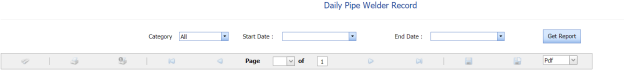
-
In the Category box, select the category from a drop-down list.
- In the Start Date and End Date boxes, select the starting and ending date to view the DPWR.
- Click Get Report.
The DPWR page shows the welder details for the selected category and period.


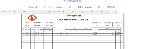
6.24.1 Print a Weekly/Monthly DPWR
If you want to print the DPWR, use  and
and  (print icons) provided in the DPWR page. See Fig 6.24.
- If you want to print the current page of the DPWR, click
 (print icon including the page number).
 -
If you want to print all the pages of the DPWR, click
 (print icon).


6.24.2 Export a Weekly/Monthly DPWR
You can export the DPWR in various formats by using the option  provided in the upper right corner of the DPWR page.
6.25 Piping Inspection Completion Status by System
The Status by System tab in the Piping menu used to view the completed status of the piping inspection based on the system data. To view the status,
- Click Status by System in the Piping menu.
The Piping Inspection Completion Status by System page opens and shows the NDT inspection details.

Figure 6.25: Piping Inspection Completion Status by System page
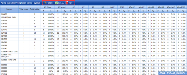
6.25.1 Export Piping Inspection Completion Status by System
You can export the piping inspection completion status in the Piping Inspection Completion Status by System page in both the pdf and excel formats by using  (PDF button) and
  (Excel button). To know how to export, see the topic, “Export P&ID list”.
6.25.2 Filter Piping Inspection Completion Status by System
If you want to filter any piping inspection completion status, you can use  (FILTER button) in the Piping Inspection Completion Status by System page. To know how to filter, see the topic, “Filter P&ID”.
6.26 Piping Inspection Completion Status by Sub System
The Status by Sub System tab in the Piping menu used to view the completed status of the piping inspection based on the sub system data. To view the status,
- Click Status by Sub System in the Piping menu.
The Piping Inspection Completion Status by Sub System page opens and shows the NDT inspection details.
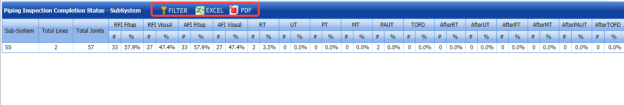
Figure 6.26: Piping Inspection Completion Status by Sub System page

6.26.1 Export Piping Inspection Completion Status by Sub System
You can export the piping inspection completion status in the Piping Inspection Completion Status by Sub System page in both the pdf and excel formats by using  (PDF button) and
  (Excel button). To know how to export, see the topic, “Export P&ID list”.
6.26.2 Filter Piping Inspection Completion Status by Sub System
If you want to filter any piping inspection completion status, you can use (FILTER button) in the Piping Inspection Completion Status by Sub System page. To know how to filter, see the topic, “Filter P&ID”.
6.27 Piping Inspection Completion Status by Line
The Status by Line tab in the Piping menu used to view the completed status of the piping inspection based on the Lines data. To view the status,
- Click Status by Line in the Piping menu.
The Piping Inspection Completion Status by Line page opens and shows the NDT inspection details.
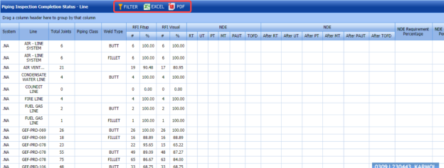
Figure 9.27: Piping Inspection Completion Status by Line page

6.27.1 Export Piping Inspection Completion Status by Line
You can export the piping inspection completion status in the Piping Inspection Completion Status by Line page in both the pdf and excel formats by using  (PDF button) and
  (Excel button). To know how to export, see the topic, “Export P&ID list”.
6.27.2 Filter Piping Inspection Completion Status by Line
If you want to filter any piping inspection completion status, you can use  (FILTER button) in the Piping Inspection Completion Status by Line page. To know how to filter, see the topic, “Filter P&ID”.
6.28 Piping Inspection Completion Status by ISO
The Status by ISO tab in the Piping menu used to view the completed status of piping inspection based on the isometric drawing data. To view the status,
- Click Status by ISO in the Piping menu.
The Piping Inspection Completion Status by ISO page opens and shows the drawing status and NDT inspection details.

Figure 6.28: Piping Inspection Completion Status by ISO page
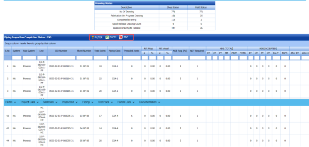
6.28.1 Export Piping Inspection Completion Status by ISO
You can export the piping inspection completion status in the Piping Inspection Completion Status by ISO page in both the pdf and excel formats by using  (PDF button) and
  (Excel button). To know how to export, see the topic, “Export P&ID list”.
6.28.2 Filter Piping Inspection Completion Status by ISO
If you want to filter any piping inspection completion status, you can use  (FILTER button) in the Piping Inspection Completion Status by ISO page. To know how to filter, see the topic, “Filter P&ID”.
6.29 Piping Inspection Completion Status by Spools
The Status by Spools tab in the Piping menu used to view the completed status of piping inspection based on the spool data. To view the status,
-
Click Status by Spools in the Piping menu.
The Piping Inspection Completion Status by Spools page opens and shows the NDT inspection details.

Figure 6.29: Piping Inspection Completion Status by Spools page
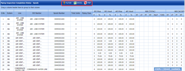
6.29.1 Export Piping Inspection Completion Status by Spools
You can export the piping inspection completion status in the Piping Inspection Completion Status by Spools page in both the pdf and excel formats by using  (PDF button) and
  (Excel button). To know how to export, see the topic, “Export P&ID list”.
6.29.2 Filter Piping Inspection Completion Status by Spools
If you want to filter any piping inspection completion status, you can use  (FILTER button) in the Piping Inspection Completion Status by Spools page. To know how to filter, see the topic, “Filter P&ID”.
6.30 Piping Inspection Completion Status by Test Pack
The Status by Test Pack tab in the Piping menu used to view the completed status of piping inspection based on the test pack data. To view the status,
- Click Status by Test Pack in the Piping menu.
The Piping Inspection Completion Status by Test Pack page opens and shows the NDT inspection details.
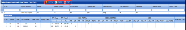
Figure 6.30: Piping Inspection Completion Status by Test Pack page

6.30.1 Export Piping Inspection Completion Status by Test Pack
You can export the piping inspection completion status in the Piping Inspection Completion Status by Test Pack page in both the pdf and excel formats by using  (PDF button) and
  (Excel button). To know how to export, see the topic, “Export P&ID list”.
6.30.2 Filter Piping Inspection Completion Status by Test Pack
If you want to filter any piping inspection completion status, you can use  (FILTER button) in the Piping Inspection Completion Status by Test Pack page. To know how to filter, see the topic, “Filter P&ID”.
6.31 Outstanding Joints
The Outstanding Joints tab in the Piping menu used to view and track the details of outstanding joints. To view the outstanding joints,
- Click Outstanding Joints in the Piping menu.
The Outstanding Joints page opens.

Figure 6.31: Outstanding Joints page
- Select the joint category from the given options such as All, Shop, and Field.
The page shows the details of outstanding joints based on the selected category.

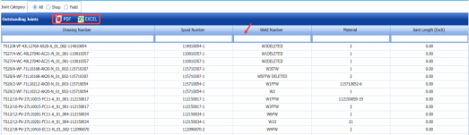
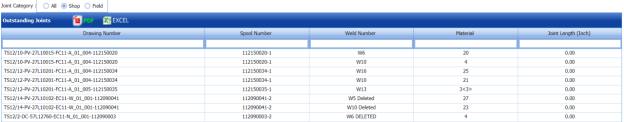
6.3.11 Export Outstanding Joints
You can export the list of outstanding joints in the Outstanding Joints page in both the pdf and excel formats by using  (PDF button) and
  (Excel button). To know how to export, see the topic, “Export P&ID list”.
6.3.12 Filter Outstanding Joints
If you want to filter any specific outstanding, you can use the filter box provided in each column of the Outstanding Joints page.

6.32 Completed Drawings
The Completed Drawings tab in the Piping menu used to view and track the details of completed drawings. To view the completed drawings details,
- Click Completed Drawings in the Piping menu.
The Completed Drawings page opens.
Figure 6.32: Completed Drawings page
- Select the joint category from the given options such as All, Shop, and Field.
The page shows the details of completed drawings based on the selected category.


6.32.1 Export Completed Drawings
You can export the list of completed drawings in the Completed Drawings page in both the pdf and excel formats by using  (PDF button) and
  (Excel button). To know how to export, see the topic, “Export P&ID list”.
6.33 Weld Progress by Date
The Weld Progress by Date tab in the Piping menu helps you to view the graphical representation of welding progress on a day basis. To view the welding progress detail,
- Click Weld Progress by Date in the Piping menu.
The Welding Progress page opens with a graphical representation.
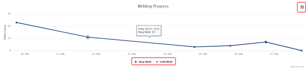
The chart shows the number of welding such as shop weld and field weld, performed on every day.
- If you want to view the progress detail of welding performed in the shop, click Shop Weld.
The chart shows the shop welding progress details.
- If you want to view the progress detail of welding performed in the field, click Field Weld.
The chart shows the field welding progress details.

6.33.1 Print a Welding Progress chart
If you want to print the welding progress chart,
- Click (menu icon) in the Weld Progress page.
-
Click Print Chart.
The chart will be printed.
6.33.2 Download a Welding Progress Chart
You can download the welding progress chart in PNG image, JPEG image, SVG vector image, and PDF formats by using the respective options provided in the menu icon.
6.34 Inspection Request Summary Report
The Inspection Request Summary tab in the Piping menu used to view the summary of inspection request. To view the inspection request summary report,
-
Click Inspection Request Summary in the Piping menu.
The Inspection Request Summary Report page opens.

Figure 6.34: Inspection Request Summary Report page
-
In the Start Date and End Date boxes, select the start and end dates.
-
Click Search.
The page shows the details of inspection request.
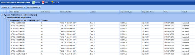
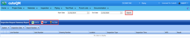

6.34.1 Export an Inspection Request Summary Report
You can export the inspection request summary report in both the pdf and excel formats by using (PDF button) and (Excel button). To know how to export, see the topic, “Export P&ID list”.
6.34.2 Filter an Inspection Request Summary
If you want to filter any inspection request detail, you can use  (FILTER button) in the Inspection Request Summary Report page. To know how to filter, see the topic, “Filter P&ID”.
6.35 Piping Progress Status Report
The Piping Progress Status Report tab in the Piping menu used to view the piping progress status report. To view the piping progress status report,
-
Click Piping Progress Status Report in the Piping menu.
The Piping Progress Status Report page opens.

Figure 9.35: Piping Progress Status Report page
-
In the From Date and To Date boxes, select the from and to dates to view the piping progress status.
-
Click Load Report.
The page shows the details of piping progress status.
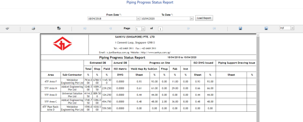

6.35.1 Print a Piping Progress Status Report
If you want to print the piping progress status report, use  and
and  (print icons) provided in the Piping Progress Status Report page. See Fig 6.35.
-
If you want to print the current page of the piping progress status report, click
 (print icon including the page number).
 -
If you want to print all the pages of the piping progress status report, click
 (print icon).


6.35.2 Export a Piping Progress Status Report
You can export the piping progress status report in various formats by using the option  provided in the upper right corner of the Piping Progress Status Report page.
6.36 Welder Defect Analysis Report
The Welder Defect Analysis Report tab in the Piping menu used to view the defect analysis report of the particular welder. To view the welder defect analysis report,
-
Click Welder Defect Analysis Report in the Piping menu.
The Welder Defect Analysis page opens.
Figure 9.36: Welder Defect Analysis page
-
In the Select Welder box, select a welder from the list of welders.
-
Click Generate Report.
The page shows the defect analysis report of the selected welder.
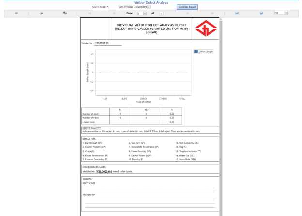


6.36.1 Print a Welder Defect Analysis Report
If you want to print the welder defect analysis report, use  and
and  (print icons) provided in the Welder Defect Analysis page. See Fig 6.36.
- If you want to print the current page of the welder defect analysis report, click
 (print icon including the page number).
 - If you want to print all the pages of the welder defect analysis report, click
 (print icon).


6.36.2 Export a Welder Defect Analysis Report
You can export the welder defect analysis report in various formats by using the option  provided in the upper right corner of the Welder Defect Analysis Report page.
6.37 Weld Traceability Record
The Weld Traceability Record tab in the Piping menu used to add a weld traceability record and track welding records.
If you want add a weld traceability record, do the following,
-
Click Weld Traceability Record in the Piping menu.
The Weld Traceability Record page opens.
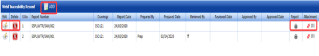
Figure 6.37: Weld Traceability Record page

6.37.1 Add a Weld Traceability Record
If you want to add a weld traceability record, do the following,
- Click
 (ADD button) in the Weld Traceability Record page. See Fig 6.37.
The page opens a new window to add the details of a weld traceability record.

 Note: The field notified with a symbol (*) is mandatory. You must enter the relevant details in that fields before saving.
 Tip: A report number for a new weld traceability record will be updated automatically in the Report Number box. If you want to change the report number, you can change.
 - In the Drawing Number box, select a drawing number from a drop-down list.
-
In the Date box, enter the date of adding the weld traceability record.
- In the Prepared By box, enter the name of a person who has prepared the weld traceability record.
- In the Prepared Date box, select the prepared date of the weld traceability record.
- In the Reviewed By box, enter the name of a person who has reviewed the weld traceability record.
- In the Reviewed Date box, select the reviewed date of the weld traceability record.
- In the Approved By boxes, enter the name of a person who has approved the weld traceability record.
- In the Approved Date box, select the approved date of the weld traceability record.
-
Click Save.
The weld traceability record is successfully added.

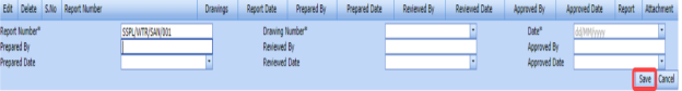


6.37.2 View a Weld Traceability Report
If you want to view a weld traceability report, click  (print icon) provided in the Report column in the Weld Traceability Record page. See Fig 6.37.
6.37.3 Attach a File into a Weld Traceability Record
If you want to attach any file with a weld traceability record listed in the Weld Traceability Record page, you can attach the file by using  (Attach icon) in the Attachment column. To know how to attach, follow the procedures given in the topic “Attach a file into P&ID”.
6.37.4 Edit a Weld Traceability Record
If you want to edit any existing weld traceability record in the Weld Traceability Record page, do the following,
- Click
 (Edit icon) in the Edit column for the respective weld traceability record.
The page shows the added details of the weld traceability record.
-
Click any box where you want to edit the details, and then edit the details in the respective box.
-
Click Save.

6.37.5 Delete a Weld Traceability Record
If you want to delete any existing system in the System page, you can use  (Delete icon) provided in the System page. To know how to delete, see the topic, “Delete P&ID”.
6.38 Add Non-Conformance Report (NCR)
NCR used to document the details of a non-conformance identified in a quality audit or other process review. The Add NCR tab in the Piping menu helps you to add an NCR in the Piping project. Do the following steps to add an NCR,
- Click Add NCR in the Piping menu.
The NCR page opens.
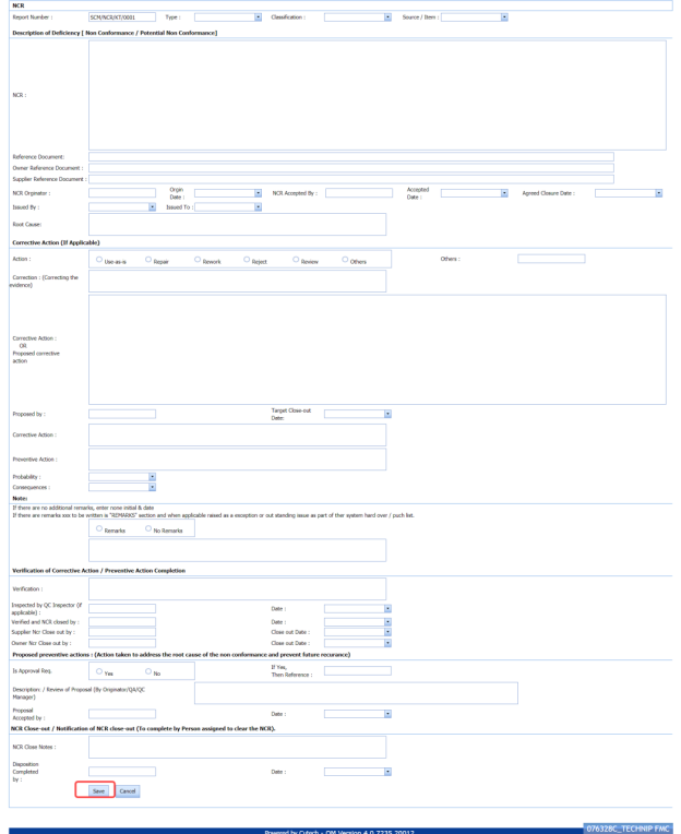
Figure 6.38: NCR page
 Tip: A report number for a new NCR will be updated automatically in the Report Number box. If you want to change the report number, you can change.
 -
In the Type box, select the type of non-conformance from a drop-down list.
- In the Classification box, select whether minor classification or major classification from a drop-down list.
- In the Source/ Item box, select the source of NCR from a drop-down list.
-
In the NCR box, enter the description for the identified deficiency of the selected non-conformance type.
-
In the Reference Document box, enter the reference document detail.
-
In the Owner Reference Document box, enter the owner reference document detail.
-
In the Supplier Reference Document box, enter the supplier reference document detail.
-
In the NCR originator box, enter the originator of NCR.
-
In the Origin Date box, select the origin date of NCR.
-
In the NCR Accepted By box, enter the name of a person who has accepted the NCR.
-
In the NCR Accepted Date box, select the NCR accepted date.
-
In the Agreed Closure Date box, select the agreed closure date.
- In the Issued By box, select the company who has issued the NCR.
- In the Issued To box, select the company for which the NCR has issued.
-
In the Root Cause box, enter the root cause detail.
- If you want to add the corrective action detail, do the following,
-
-
In the Action box, select any corrective action from the given options.
-
In the Corrective Action box, enter the corrective action detail.
- In the Proposed by box, enter the name of a person who has proposed the corrective action.
- In the Target Close-out Date box, select the target close out date.
-
In the Preventive Action box, enter the preventive actions.
- In the Probability box, select the probability percentage of non-conformance.
- In the consequences box, select the consequences level you have faced.
-
-
-
If you want to add any remarks, click Remarks option and enter your remarks, otherwise click No Remarks option.
-
In the Verification box, enter the verification detail on completion of corrective action/ preventive action.
-
In the Inspected by QC Inspector, and Date boxes, enter the name of the QC inspector who has inspected the NCR, and date, respectively.
-
In the Inspected by QC Inspector, and Date boxes, enter the name of the QC inspector who has inspected the NCR, and date, respectively.
- In the Supplier NCR Close out by, and Close Out Date boxes, enter the name of a person who has closed the supplier NCR, and close out date, respectively.
- In the Owner NCR Close out by, and Close Out Date boxes, enter the name of a person who has closed the owner NCR, and close out date, respectively.
- In the Approval Req box, if you need approval, click Yes, otherwise click
- If you have selected Yes, you must enter the reference detail in the If Yes, Then Reference
-
In the Description box, enter the description of proposal.
-
In the Proposal Accepted by, and Date boxes, enter the name of a person who has accepted the proposal, and date, respectively.
-
In the NCR Close Notes box, enter the NCR close notes.
-
In the Disposition Completed by, and Date boxes, enter the name of a person who has completed the disposition, and date, respectively.
-
Click Save.


The NCR is successfully added.
6.39 View NCR
The View NCR tab helps you to view and edit the details of added NCR. You can also add a new NCR by using the add option. To navigate to View NCR,
-
Click View NCR in the NCR menu.
The View NCR page opens with an added NCR.
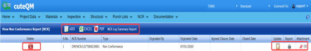
Figure 6.39: View NCR page

6.39.1 Add an NCR
If you want to add a new NCR, follow the same procedure in the topic, “Add NCR”.
6.39.2 View an NCR Log Summary Report
If you want to view an NCR log summary report, click  provided in the upper side of the View NCR page. See Fig 6.39.
6.39.3 Attach a File into an NCR
If you want to attach any file with an NCR listed in the View NCR page, you can attach the file by using  (Attach icon) in the Attachment column. To know how to attach, follow the procedures given in the topic “Attach a file into P&ID”.
6.39.4 Update an NCR
If you want to update any existing NCR in the View NCR page, click  (Update icon) in the Update column for the respective NCR. Edit the details in the respective box you want.
6.39.5 Export an NCR
You can export a list of NCRs added in the View NCR page in both the pdf and excel formats by using  (PDF button) and
  (Excel button). To know how to export, see the topic, “Export P&ID list”.
6.39.6 Delete an NCR
If you want to delete any existing NCR in the View NCR page, you can use  (Delete icon) provided in the View NCR page. To know how to delete, see the topic, “Delete P&ID”.
6.40 Spools Generate Barcode & QR Code
By using the Spools Generate Barcode & QR Code tab in the Piping menu, you can generate the bar code and QR code for the spools for which you have added.
-
Click Spools Generate Barcode & QR Code in the Piping menu.
The Spools Generate Barcode page opens.

Figure 6.40: Spools Generate Barcode page
-
Select the checkbox of the spool for which you want to generate barcode and QR code.
-
If you want to generate the barcode, click
 (Print Barcode button).
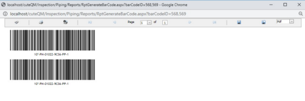
-
If you want to generate the QR code, click
 (Print QR code button).
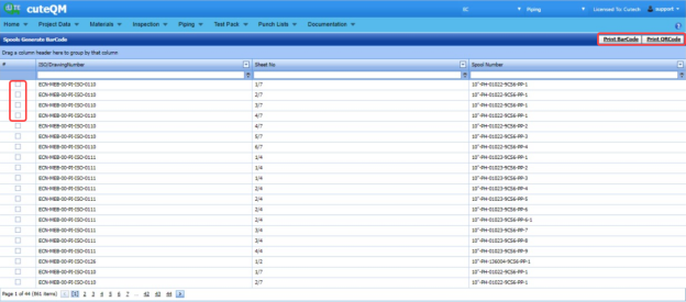


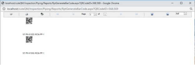
6.41 RT Weekly Report
The RT Weekly Report tab in the Piping menu used to view the week wise RT inspection status. To view the RT inspection status,
- Click RT Weekly Report in the Piping menu.
The RT Weekly Report page opens and shows the RT inspection status.
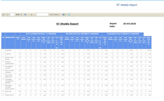

6.42 Weld Summary Sheet
The Weld Summary sheet tab in the Piping menu used you to view a summary report of pipe welding inspection. To view the summary report,
- Click Weld Summary sheet in the Piping menu.
The Piping Weld Inspection Log Sheet page opens.
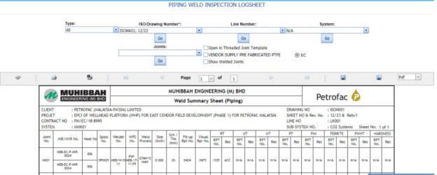
Figure 9.42: Piping Weld Inspection Log Sheet page
- In the Type box, select the type of joint.
-
Do one of the following steps,
-
- In the ISO Drawing Number box, select the isometric drawing number from a drop-down list.
- In the Line Number box, select the line number from a drop-down list.
- In the System box, select the system from a drop-down list.
-
- In the Joints box, select a joint from a list of joints loaded based on the selected ISO.
-
Click Go.
- If you want to open the log sheet in a threaded joint template, click the checkbox of the Open in Threaded Joint Template
- If you want to open the log sheet for Vendor supply pre-fabricated PTFE, click the checkbox of the VENDOR SUPPLY PRE-FABRICATED PTFE
-
The pipe welding inspection log sheet opens for the selected option.


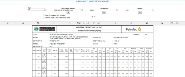
6.42.1 Print a Weld Summary Sheet
If you want to print the weld summary sheet, use  and
and  (print icons) provided in the Weld Summary Sheet page.
- If you want to print the current page of the weld summary sheet, click
 (print icon including the page number).
 - If you want to print all the pages of the weld summary sheet, click
 (print icon).


6.42.2 View a Weld Summary Sheet
You can view the weld summary sheet in various formats by using the option  provided in the upper right corner of the Weld Summary Sheet page.
6.43 Inspection Status Report
Inspection Status Report shows the overall inspection reports such as from fit-up inspection status to NDT inspection status.
If you want to view an inspection status report, do the following steps,
- Click Inspection Status Report in the Piping menu.
The Inspection Status Report page opens.
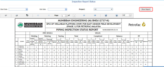
Figure 6.43: Inspection Status Report page
-
In the Start Date and End Date boxes, select the start and end dates.
-
In the Project box, select the project from a drop-down list.
-
Click Show Report.
The Inspection Status Report page shows the spool information, RFI fit-up, RFI weld VI, and NDT inspection status.

6.43.1 Print an Inspection Status Report
If you want to print the inspection status report, use  and
and  (print icons) provided in the Inspection Status Report page. See Fig 6.43.
-
If you want to print the current page of the inspection status report, click
 (print icon including the page number).
 - If you want to print all the pages of the inspection status report, click
 (print icon).


6.43.2 Export an Inspection Status Report
You can export the inspection status report in various formats by using the option  provided in the upper right corner of the Inspection Status Report page.
6.44 Surveillance Entry
The Surveillance Entry tab in the Piping menu helps you to add the observation details of various category, which is done by an inspector.
If you want add a surveillance entry, do the following,
-
Click Surveillance Entry in the Piping menu.
The Surveillance page opens.

Figure 6.44: Surveillance page
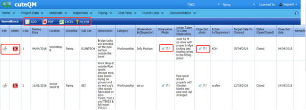
6.44.1 Add a Surveillance Entry
If you want to add a surveillance entry, do the following,
-
Click
 (ADD button) in the Surveillance page. See Fig 6.44.
A new window opens to add a surveillance entry.

 Note: The fields notified with a symbol (*) are mandatory. You must enter the relevant details in that fields before saving.
 - In the Surveillance Date box, select the surveillance date.
-
In the Category box, select a surveillance category from a drop-down list.
-
In the Location box, select a location where the surveillance has done.
-
In the Sub Contractor box, select the sub-contractor from a drop-down list.
- In the Observation By Inspector box, enter the name of the inspector who has done the observation.
-
In the Action by (Supervisor) box, enter the name of the supervisor who has done the action.
-
In the Target Date to Close out box, select the target date to close out the observation.
-
In the Remarks box, enter your remarks if any.
-
In the Observation box, enter the observation’s description.
-
In the Action Taken To Close Observation box, enter the actions to close out the observation.
- In the Status box, select the status Open or Close based on the observation.
-
Click Save.

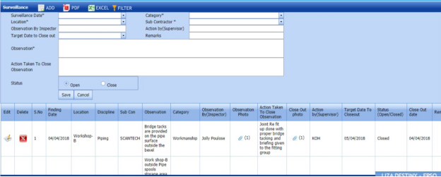

The surveillance entry is successfully added.
6.44.2 Attach a File into a Surveillance Entry
If you want to attach any file with the surveillance entry listed in the Surveillance page, you can attach the file by using  (Attach icon) in the Attachment column. To know how to attach, follow the procedures given in the topic “Attach a file into P&ID”.
6.44.3 Edit a Surveillance Entry
If you want to edit any existing surveillance entry in the Surveillance page, do the following,
- Click
 (Edit icon) in the Edit column for the respective surveillance entry. See Fig 6.44.
 - Click any box where you want to edit the details, and then edit the details in the respective box.
-
Click Save.

6.44.4 Delete a Surveillance Entry
If you want to delete any from the list, you can use (Delete icon) provided in the Delete column of the Surveillance page, See Fig 6.44. To know how to delete, see the topic, “Delete P&ID”.
6.44.5 Export a Surveillance Entry
You can export a list of surveillance entry added in the Surveillance page in the pdf and excel formats by using  (PDF button) and
  (Excel button). To know how to export, see the topic, “Export P&ID list”.
6.44.6 Filter a Surveillance Entry
If you want to filter any surveillance entry from the list in the Surveillance page, you can use  (FILTER button) located on the Surveillance page. To know how to filter, see the topic, “Filter P&ID”.
6.45 Surveillance Report
Once you have added the surveillance entry by using the Surveillance Entry tab, you can view a surveillance report by using the Surveillance Report tab in the Piping menu. If you want to view a surveillance report, do the following steps,
- Click Surveillance Report in the Piping menu.
The Surveillance Report page opens.
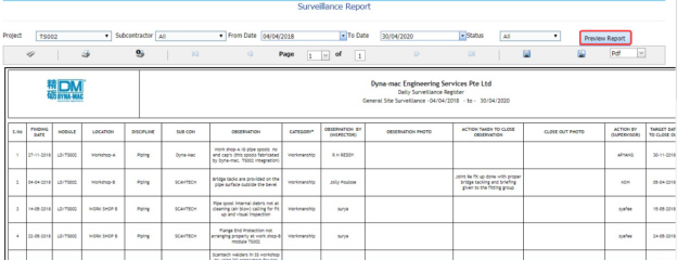
Figure 6.45: Surveillance Report page
-
In the Project box, select a project from a drop-down list.
-
In the Subcontractor box, select a sub-contractor from a drop-down list.
-
In the From Date and To Date boxes, select the from and to dates in respectively.
-
In the Status box, select the status from a drop-down list.
-
Click Preview Report.
The surveillance report will be displayed for the selected dates and status.

6.45.1 Print a Surveillance Report
If you want to print a surveillance report, use  and
and  (print icons) provided in the Surveillance Report page. See Fig 6.45.
-
If you want to print the current page of the surveillance report, click
 (print icon including the page number).
 -
If you want to print all the pages of the surveillance report, click
 (print icon).


6.45.2 Export a Surveillance Report
You can export the surveillance report in various formats by using the option  provided in the upper right corner of the Surveillance Report page.
6.46 Surveillance Category Report
The Surveillance Categories Report tab in the Piping menu shows the surveillance report based on the category wise status.
-
Click Surveillance Categories Report in the Piping menu.
The Surveillance Category Wise Status Report page opens.
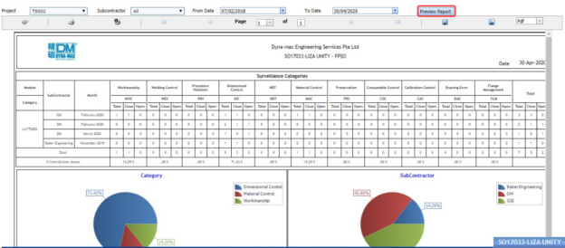
Figure 6.46: Surveillance Report page
-
In the Project box, select a project from a drop-down list.
-
In the Subcontractor box, select a sub-contractor from a drop-down list.
-
In the From Date and To Date boxes, select the from and to dates in respectively.
-
In the Status box, select the status from a drop-down list.
-
Click Preview Report.

The surveillance report will be displayed based on the category wise status.
6.46.1 Print a Surveillance Category Wise Status Report
If you want to print a surveillance report, use  and
and  (print icons) provided in the Surveillance Category Wise Status Report page. See Fig 6.46.
- If you want to print the current page of the surveillance report, click
 (print icon including the page number).
 -
If you want to print all the pages of the surveillance report, click
 (print icon).


6.46.2 Export a Surveillance Category Wise Status Report
You can export the surveillance report in various formats by using the option  provided in the upper right corner of the Surveillance Category Wise Status Report page.
6.47 Blasting and Painting View
The Blasting and Painting View tab in the Piping menu used to add the blasting and painting inspection report.
-
Click Blasting and Painting View in the Piping menu.
The Blasting and Painting page opens.
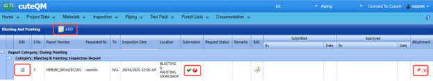
Figure 6.47: Blasting and Painting page

6.47.1 Add a Blasting and Painting Report
If you want to add a blasting and painting report, do the following steps,
-
Click
 (ADD button) in the Blasting and Painting page. See Fig 6.47.
The page opens a new window to add the details of the blasting and painting report.

-
In the Requested by box, enter the name of a person who has requested the blasting and painting report.
-
In the Requested To box, enter the name of a person for whom you want to send the blasting and painting report.
- In the Description / Spec,Ref.No box, select the specification report number.
- In the Inspection Date & Time box, select the inspection date and time.
-
In the Location box, select the inspection location.
-
In the Requisition box, enter the requisition detail.
-
In the System box, select the system.
-
In the Report Type field, select the report type which you want to create.
Before saving the added request, you must add the spools.
 Note: You can add multiple spools for one request.
The page shows a list of spools. If you want to add spools for the request, do the following steps,
-
Click
 (Add icon) of the respective spools you want to add.
The added spools will be moved and listed in the right side of the page.
-
Click Save NDT Request.
The added report will be listed in the Blasting and Painting page.

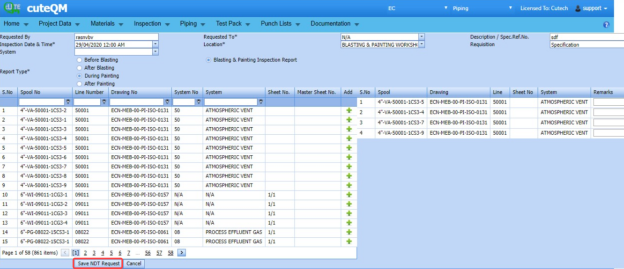


6.47.2 Edit a Blasting and Painting Report
If you want to edit any existing blasting and painting report in the Blasting and Painting page, do the following steps,
- Click
 (Edit icon) in the Edit column for the respective blasting and painting See Fig 6.47.
The Blasting and Painting page opens with the details of the selected blasting and painting report.
- Click any box where you want to edit the details, and then edit the details in the respective box.
-
Click Save.

6.47.3 Submit and Approve a Blasting and Painting Report
Once you have added the blasting and painting report, the Submission column in the Blasting and Painting page is appeared with  (Submit and Reject icons).
- If you want to submit the blasting and painting report, click
 (Submit icon) in the Submission Otherwise click
 (Reject icon) to reject the request.
Once you have submitted the blasting and painting report, the Request Status column in the Blasting and Painting page is appeared with
 (Approve and Reject icons).
 - If you want to approve the blasting and painting report, click
 (Approve icon) in the Request Status Otherwise click
 (Reject icon) to reject the request.


6.47.4 Attach a File into a Blasting and Painting Report
If you want to attach a file with any existing blasting and painting report listed in the Blasting and Painting page, you can attach the file by using  (Attach icon) in the Attachment column. To know how to attach, follow the procedures given in the topic “Attach a file into P&ID”.
6.48 NDT Summary Report
The NDT Summary Report tab in the Piping menu shows the summary report of the NDT inspection.
- Click NDT Summary Report in the Piping menu.
The NDT Summary Report page opens.
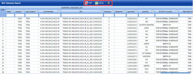
Figure 6.48: NDT Summary Report page

6.48.1 Print an NDT Summary Report
If you want to print an NDT summary report, click  (print icon) provided in the upper side of the NDT Summary Report page. See Fig 6.48.
6.48.2 Export an NDT Summary Report
You can export a list of NDT summary report added in the NDT Summary Report page in the pdf and excel formats by using (PDF button) and
  (Excel button). To know how to export, see the topic, “Export P&ID list”.
6.49 Component Summary Report
Component Summary Report shows the component summary details. If you want to view a component summary report, do the following steps,
- Click Component Summary Report in the Piping menu.
The Component Summary Report page opens.
Figure 6.49: Component Summary Report page
- In the From Date and To Date boxes, select the from and to dates in respectively.
-
Click Show Report.
The component summary report opens for the selected dates.

6.49.1 Print a Component Summary Report
If you want to print a component summary report, use  and
and  (print icons) provided in the Component Summary Report page. See Fig 6.49.
- If you want to print the current page of the component summary report, click
 (print icon including the page number).
 - If you want to print all the pages of the component summary report, click
 (print icon).


6.49.2 Export a Component Summary Report
You can export the component summary report in various formats by using the option  provided in the upper right corner of the Component Summary Report page.
6.50 NDT Performance Report (RT & UT)
NDT Performance Report shows the performance details of RT and UT. If you want to view an NDT performance report, do the following steps,
- Click NDT Performance Report in the Piping menu.
The NDT Performance Report page opens.
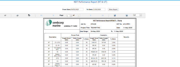
Figure 6.50: NDT Performance Report page
-
In the From Date and To Date boxes, select the from and to dates in respectively.
-
Click Show Report.
The NDT performance report opens for the selected dates.

6.50.1 Print an NDT Performance Report
If you want to print an NDT performance report, use  and
and  (print icons) provided in the NDT Performance Report page. See Fig 6.50.
- If you want to print the current page of the NDT performance report, click
 (print icon including the page number).
 -
If you want to print all the pages of the NDT performance report, click
 (print icon).


6.50.2 Export NDT Performance Report
You can export the NDT performance report in various formats by using the option  provided in the upper right corner of the NDT Performance Report page.
6.51 Pipe Flushing Check List
The Pipe Flushing Check List tab in the Piping menu used to add the pipe flushing check list detail.
- Click Pipe Flushing Check List in the Piping menu.
-
The Pipe Flushing Check List page opens.
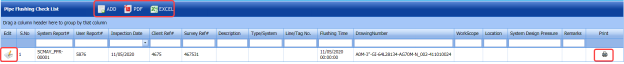
Figure 6.51: Pipe Flushing Check List page
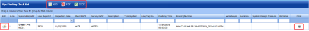
6.51.1 Add a Pipe Flushing Check List
- Click
 (ADD button) in the Pipe Flushing Check List See Fig 6.51.
A new window opens to add a pipe flushing check list.
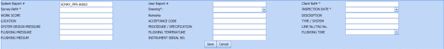
 Note: The fields notified with a symbol (*) are mandatory. You must enter the relevant details in that fields before saving.
 -
In the User Report box, enter the user report number.
-
In the Client Ref box, enter the client reference number.
-
In the Survey Ref box, enter the survey reference number.
-
In the Drawing box, select a drawing number.
-
In the Inspection Date box, select the inspection date.
-
In the Work Scope box, enter the work scope detail.
-
In the Remarks box, enter your remarks if any.
-
In the Description box, enter the description for check list.
-
In the Location box, enter the name of a location.
-
In the Acceptance Code box, enter the acceptance code.
-
In the Flushing Pressure box, enter the flushing pressure value.
-
In the Flushing Temperature box, enter the flushing temperature value.
-
In the Flushing Time box, select the flushing time.
-
In the Flushing Medium box, enter the flushing medium name.
-
In the Instrument Serial No box, enter the instrument serial number.
-
Click Save.


The pipe flushing checklist is successfully added.
6.51.2 Edit a Pipe Flushing Check List
If you want to edit any existing pipe flushing check list in the Pipe Flushing Check List page, do the following steps,
- Click
 (Edit icon) in the Edit column for the respective pipe flushing check list. See Fig 6.51.
A new window opens with the added details of the pipe flushing check list.
-
Click any box where you want to edit the details, and then edit the details in the respective box.
-
Click Save.

6.51.3 Export a Pipe Flushing Check List
You can export a list of pipe flushing check list added in the Pipe Flushing Check List page in the pdf and excel formats by using  (PDF button) and
  (Excel button). To know how to export, see the topic, “Export P&ID list”.
6.51.4 Filter a Pipe Flushing Check List
If you want to filter any pipe flushing check list, you can use (FILTER button) in the Pipe Flushing Check List page. To know how to filter, see the topic, “Filter P&ID”.
6.51.5 Print a Pipe Flushing Check List
If you want to print a pipe flushing check list, click (print icon) provided in the Print column of the Pipe Flushing Check List page. See Fig 6.51.
6.52 Pipe Inspection Check List
The Pipe Inspection Check List tab in the Piping menu used to add the pipe inspection check list detail.
-
Click Pipe Inspection Check List in the Piping menu.
The Pipe Inspection Check List page opens.
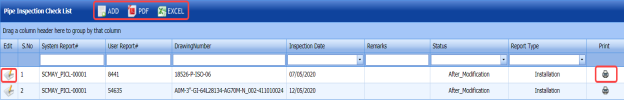
Figure 6.52: Pipe Inspection Check List page

6.52.1 Add a Pipe Inspection Check List
-
Click
 (ADD button) in the Pipe Inspection Check List page. See Fig 6.52.
A new window opens to add a pipe inspection check list.

 Note: The fields notified with a symbol (*) are mandatory. You must enter the relevant details in that fields before saving.
 -
In the User Report Number box, enter the user report number.
-
In the Drawing box, select a drawing number.
-
In the Date box, select the inspection date.
-
In the Remarks box, enter your remarks if any.
-
In the Status field, select the status of the check list.
-
In the Report Type box, select the report type of the check list.
-
Click Save.

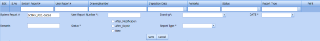

The pipe inspection checklist is successfully added.
6.52.2 Edit a Pipe Inspection Check List
If you want to edit any existing pipe inspection check list in the Pipe Inspection Check List page, do the following steps,
- Click
 (Edit icon) in the Edit column for the respective pipe inspection check list. See Fig 6.52.
A new window opens with the added details of the pipe inspection check list.
-
Click any box where you want to edit the details, and then edit the details in the respective box.
-
Click Save.

6.52.3 Export a Pipe Inspection Check List
You can export a list of pipe inspection check list added in the Pipe Inspection Check List page in the pdf and excel formats by using  (PDF button) and
  (Excel button). To know how to export, see the topic, “Export P&ID list”.
6.52.4 Filter a Pipe Inspection Check List
If you want to filter any pipe inspection check list, you can use  (FILTER button) in the Pipe Inspection Check List page. To know how to filter, see the topic, “Filter P&ID”.
6.52.5 Print a Pipe Inspection Check List
If you want to print a pipe Inspection check list, click (print icon) provided in the Print column of the Pipe Inspection Check List page. See Fig 6.52.
6.53 Warning Letter
The Warning Letter Report tab in the Piping menu helps you to add a warning letter that addresses the performance issue of a worker. The warning letter explains about the mistakes done by the worker. If you want to add a warning letter against any worker, do the following,
- Click Warning Letter in the Piping menu.
The Warning Letter Report page opens.
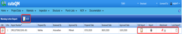
Figure 6.53: Warning Letter Report page

6.53.1 Add a Warning Letter Report
If you want to add a warning letter report,
- Click
 (ADD button) in the Warning Letter Report See Fig 6.53.
A new window opens to add a warning letter report.
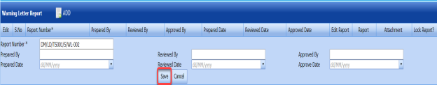
 Tip: A report number for a new warning letter report will be updated automatically in the Report Number box.
 - In the Prepared By box, enter the name a person who has prepared the warning letter report.
-
In the Prepared Date box, enter the prepared date of the warning letter report.
-
In the Reviewed By box, enter the name a person who has reviewed the warning letter report.
-
In the Reviewed Date box, enter the reviewed date of the warning letter report.
-
In the Approved By box, enter the name a person who has approved the warning letter report.
-
In the Approved Date box, enter the approved date of the warning letter report.
-
Click Save.


The warning letter report is successfully added. Once you have added the warning letter report, you must add the warning letter details.
6.53.2 Add Warning Letter Details
- Click
 (Edit icon) in the Edit Report column of the Warning Letter Report page. See Fig 6.53.
The Warning Letter Details window opens including a default warning letter template.

-
In the Date box, select the date of issuing the warning letter.
-
In the From box, enter the name of a person who issues the warning letter.
-
In the To box, enter the name of a person who receives the warning letter.
-
In the Attention box, enter the relevant detail.
-
In the Subject box, enter the subject of this warning letter.
-
In the Remarks box, enter your remarks if any.
-
In the Content box, if you want to change any information given in the template, you can change.
-
Click Save Details.

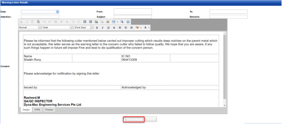
6.53.3 Print a Warning Letter Report
If you want to print a warning letter report, click  (print icon) provided in the Report column of the Warning Letter Report page. See Fig 6.53.
 Tip: If you want to lock any warning letter report, click the check box provided in the Lock Report? column of the Warning Letter Report page. See Fig 6.53.
6.53.4 Attach a File into a Warning Letter Report
If you want to attach any file with any warning letter report listed in the Warning Letter Report page. To know how to attach, follow the procedures given in the topic “Attach a file into P&ID”.
6.54 Welder Performance Summary
The Welder Performance Summary tab in the Piping menu used to add welder performance record. To add the welder performance record,
- Click Welder Performance Summary in the Piping menu.
The Welder Performance Record page opens.
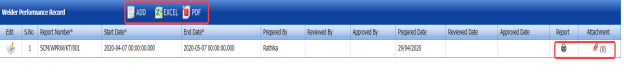
Figure 6.54: Welder Performance Record page

6.54.1 Add a Welder Performance Record
- Click
 (ADD button) in the Welder Performance Record See Fig 6.54.
A new window opens to add a welder performance record.

 Note: The fields notified with a symbol (*) are mandatory. You must enter the relevant details in that fields before saving.
 - In the Start Date and End Date boxes, select the start and end dates.
-
In the Prepared By box, enter the name a person who has prepared the welder performance record.
-
In the Prepared Date box, enter the prepared date of the welder performance record.
-
In the Reviewed By box, enter the name a person who has reviewed the welder performance record.
-
In the Reviewed Date box, enter the reviewed date of the welder performance record.
-
In the Approved By box, enter the name a person who has approved the welder performance record.
-
In the Approved Date box, enter the approved date of the welder performance record.
-
Click Save.

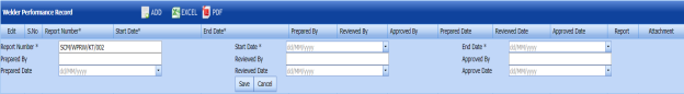

The welder performance record is successfully added.
6.54.2 Edit a Welder Performance Record
If you want to edit any existing welder performance record in the Welder Performance Record page, do the following steps,
- Click
 (Edit icon) in the Edit column for the respective welder performance record. See Fig 6.54.
A new window opens with the added details of the welder performance record.
- Click any box where you want to edit the details, and then edit the details in the respective box.
-
Click Save.

6.54.3 Export a Welder Performance Record
You can export a list of welder performance records added in the Welder Performance Record page in the pdf and excel formats by using  (PDF button) and
  (Excel button). To know how to export, see the topic, “Export P&ID list”.
6.54.4 Filter a Welder Performance Record
If you want to filter any welder performance record, you can use  (FILTER button) in the Welder Performance Record page. To know how to filter, see the topic, “Filter P&ID”.
6.54.5 Print a Welder Performance Record
If you want to print a welder performance record, click  (print icon) provided in the Print column of the Welder Performance Record page. See Fig 6.54.
6.54.5 Attach a File into a Welder Performance Record
If you want to attach a file with any existing welder performance record listed in the Welder Performance Record page, you can attach the file by using (Attach icon) in the Attachment column. To know how to attach, follow the procedures given in the topic “Attach a file into P&ID”.
6.55 Weld Repair Log Report
Weld Repair Log Report shows the weld repair log details. If you want to view a weld repair log report, do the following steps,
-
Click Weld Repair Log Report in the Piping menu.
The Weld Repair Log Report page opens.
Figure 6.55: Weld Repair Log Report page

6.55.1 Print a Weld Repair Log Report
If you want to print a weld repair log report, use  and
and  (print icons) provided in the Weld Repair Log Report page. See Fig 6.55.
- If you want to print the current page of the weld repair log report, click
 (print icon including the page number).
 -
If you want to print all the pages of the weld repair log report, click
 (print icon).


6.55.2 Export a Weld Repair Log Report
You can export the weld repair log report in various formats by using the option provided in the upper right corner of the Weld Repair Log Report page.
6.56 AFI Report Status
The AFI Report Status tab in the Piping menu shows the AFI report status.
- Click AFI Report Status in the Piping menu.
The AFI Report Status page opens.

Figure 6.56: AFI Report Status page
-
In the Project box, select a project from a drop-down list.
-
In the Category box, select a category from a drop-down list.
-
In the From Date and To Date boxes, select the from and to dates in respectively.
-
Click Show Report.
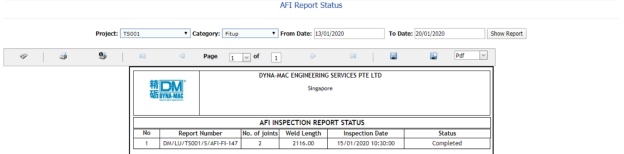
The AFI report status will be displayed.
6.56.1 Print an AFI Report Status
If you want to print an AFI report status, use  and
and  (print icons) provided in the AFI Report Status page. See Fig 6.56.
- If you want to print the current page of the AFI report status, click
 (print icon including the page number).
 -
If you want to print all the pages of the AFI report status, click
 (print icon).


6.56.2 Export an AFI Report Status
You can export the AFI report status in various formats by using the option provided in the upper right corner of the AFI Report Status page.
6.57 Status by ISO for NDT Requirement
The Status by ISO for NDT Requirement tab in the Piping menu used to view the ISO status for NDT requirement.
- Click Status by ISO for NDT Requirement in the Piping menu.
The page shows the status by ISO for NDT requirement.

Figure 6.57: Status by ISO for NDT Requirement page
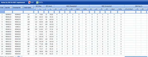
6.57.1 Export Status by ISO for NDT Requirement
You can export the status in the Status by ISO for NDT Requirement page in the pdf and excel formats by using (PDF button) and (Excel button). To know how to export, see the topic, “Export P&ID list”.
6.58 Piping Widget
The Piping Widget tab in the Piping menu used to view overall summary of the piping NDT, NDT number of joint status, and overall welder rejected status.
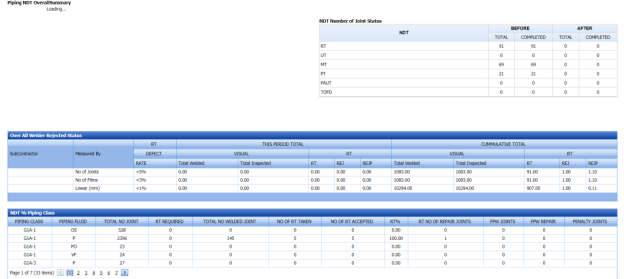
6.59 Welder Not Welded List
The Welder Not Welded List tab in the Piping menu used to view the list of welders who has not performing the welding work for more than 15 days. If you want to view the welder list,
- Click Welder Not Welded List in the Piping menu.
The Welder Recently Not Welded List page shows a list of welders including their NRIC and welder numbers, last weld date, and no of days not performing welding.
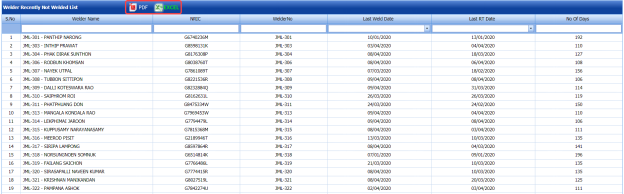
Figure 6.59: Welder Recently Not Welded List page
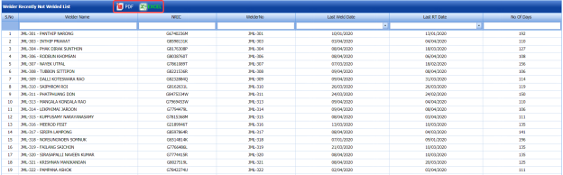
6.59.1 Export Welder Not Welded List
You can export the welder list in the Welder Recently Not Welded List page in the pdf and excel formats by using  (PDF button) and (Excel button). To know how to export, see the topic, “Export P&ID list”.
6.60 Daily Piping Production Log Report
The Daily Piping Production Log Report tab in the Piping menu used to view the production details in the piping project on a daily basis. If you want to view the production log report,
- Click Daily Piping Production Log Report in the Piping menu.
The Daily Piping Production Log Report page shows production details in the piping project on a daily basis.
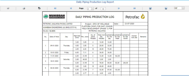
Figure 6.60: Daily Piping Production Log Report page

6.60.1 Print a Daily Piping Production Log Report
If you want to print a daily piping production log report, use  and
and  (print icons) provided in the Daily Piping Production Log Report page. See Fig 6.60.
- If you want to print the current page of the daily piping production log report, click
 (print icon including the page number).
 -
If you want to print all the pages of the daily piping production log report, click
 (print icon).


6.60.2 Export a Daily Piping Production Log Report
You can export the daily piping production log report in various formats by using the option  provided in the upper right corner of the Daily Piping Production Log Report page.
6.61 RFI Log Report
6.62 NDT Log Report
The NDT Log Report tab in the Piping menu used to view the NDT log report. If you want to view the NDT log report,
- Click NDT Log Report in the Piping menu.
The NDT Log Report page shows NDT log report.
- In the From Date and To Date boxes, select the from and to dates.
-
Click Load Report.
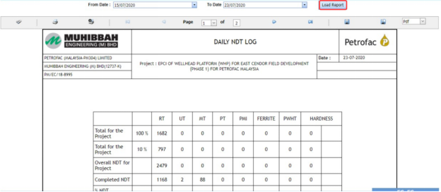
Figure 6.62: NDT Log Report page
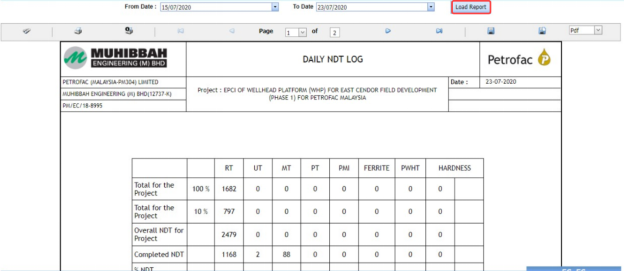
6.62.1 Print an NDT Log Report
If you want to print an NDT log report, use  and
and  (print icons) provided in the NDT Log Report page. See Fig 6.62.
- If you want to print the current page of the NDT log report, click
 (print icon including the page number).
 -
If you want to print all the pages of the NDT log report, click
 (print icon).


6.62.2 Export an NDT Log Report
You can export the NDT log report in various formats by using the option  provided in the upper right corner of the NDT Log Report page.
6.63 DB Summary Report
The DB Summary Report tab in the Piping menu used to view the DB summary report. If you want to view the DB summary report,
- Click DB Summary Report in the Piping menu.
The Total Piping DB Summary page shows the DB summary report.

Figure 6.63: Total Piping DB Summary page
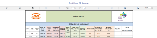
6.63.1 Print a DB Summary Report
If you want to print a DB summary report, use  and
and  (print icons) provided in the Total Piping DB Summary page. See Fig 6.63.
- If you want to print the current page of the DB summary report, click
 (print icon including the page number).
 - If you want to print all the pages of the DB summary report, click
 (print icon).


6.63.2 Export a DB Summary Report
You can export the DB summary report in various formats by using the option  provided in the upper right corner of the Total Piping DB Summary page.
6.64 Weld Repair Report
Weld Repair Report shows the weld repair details. If you want to view a weld repair report, do the following steps,
-
Click Weld Repair Report in the Piping menu.
The Weld Repair Report page opens.
- In the Repair No box, select the repair number.
- In the ISO/Drawing Number box, select the ISO drawing number.
-
Click Go.
The weld repair details open for the selected repair number.

Figure 6.64: Weld Repair Report page
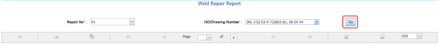
6.64.1 Print a Weld Repair Report
If you want to print a weld repair report, use  and
and  (print icons) provided in the Weld Repair Report page. See Fig 6.64.
- If you want to print the current page of the weld repair report, click
 (print icon including the page number).
 - If you want to print all the pages of the weld repair report, click
 (print icon).


6.64.2 Export a Weld Repair Report
You can export the weld repair report in various formats by using the option  provided in the upper right corner of the Weld Repair Report page.
6.65 Pending NDT Log Report
Pending NDT Log Report shows the pending NDT log details. If you want to view the pending NDT log report, do the following steps,
- Click Pending NDT Log Report in the Piping menu.
The Pending NDT Log page opens.
-
In the ISO/Drawing Number box, select the ISO drawing number.
-
Click Show Report.
The pending NDT log details open for the selected ISO drawing number.

Figure 6.65: Pending NDT Log page
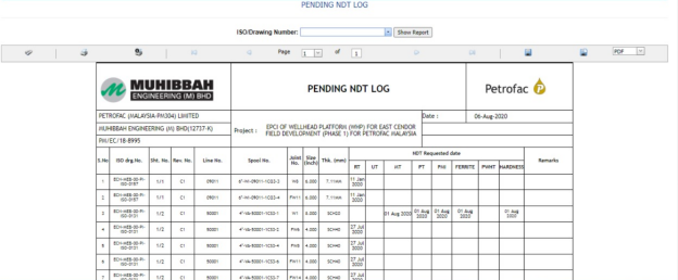
6.65.1 Print a Pending NDT Log Report
If you want to print a pending NDT log report, use  and
and  (print icons) provided in the Pending NDT Log page. See Fig 6.65.
- If you want to print the current page of the pending NDT log report, click
 (print icon including the page number).
 -
If you want to print all the pages of the pending NDT log report, click
 (print icon).


6.65.2 Export a Pending NDT Log Report
You can export the pending NDT log report in various formats by using the option  provided in the upper right corner of the Pending NDT Log page.
6.66 RT Films Status Report
The RT Film Status Report tab in the Piping menu used to view the RT film status. If you want to view the RT film status report,
- Click RT Film Status Report in the Piping menu.
The RT Film Report page shows the RT film status.
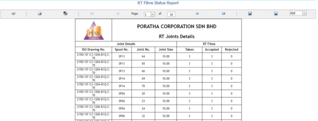
Figure 6.66: RT Film Status Report page

6.66.1 Print an RT Film Status Report
If you want to print an RT film status report, use  and
and  (print icons) provided in the RT Film Status Report page. See Fig 6.66.
- If you want to print the current page of the RT film status report, click
 (print icon including the page number).
 - If you want to print all the pages of the RT film status report, click
 (print icon).


6.66.2 Export an RT Film Status Report
You can export the RT film status report in various formats by using the option  provided in the upper right corner of the RT Film Status Report page.
No Comments