
Electrical
1. Project Data
The Project Data menu in the cuteQM app helps you to add the master data. Once you click the Project Data menu, the following tabs open,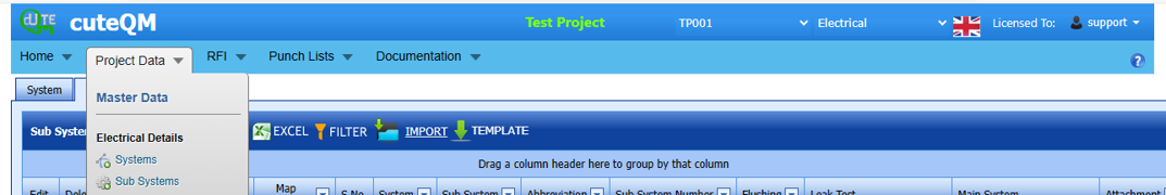
1.0 Systems
You can add the details of systems to be used in the Electrical project by using the Systems tab in the Project Data menu. If you
want to navigate to Systems,
1.Click Systems in the Project Data menu,
The System page opens.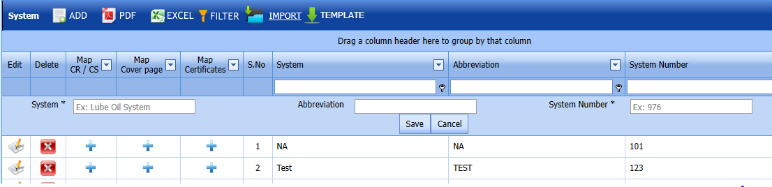 Fig 1.0 Systems Page
1.1.1 Add a System
If you want to add a new system, do the following steps,
1. Click  (ADD button) in the System page. See Fig 1.1.1
A new window opens to add a new system.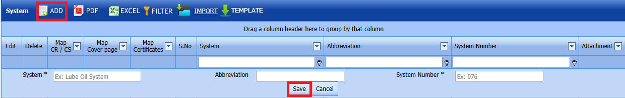
Fig 1.1.1 Add a System Page
-
 Note: The fields notified with a symbol (*) are mandatory. You must enter the relevant details in that fields before saving.
 - In the System box, enter the system name.
-
In the Abbreviation box, enter the abbreviation for the system name.
-
In the System Number box, enter the system number.
-
Click Save.
The system is successfully added and listed in the System page.

-
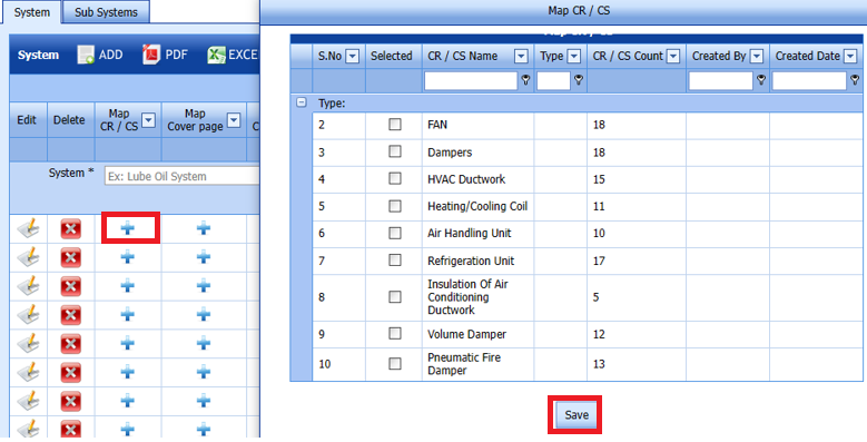
 Note: If you want to map cover page for any added system, click the respective
  (Add icon) provided in the Map Cover Page column and add the cover pages.
 -
If you want to map certificates for any added system, click the respective (Add icon) provided in the Map Certificates column and add the cover pages.
-
If you want to map Check Record/Check Sheet (CR/CS) for any added system, click the respective (Add icon) provided in the Map CR/CS column and add the cover pages.

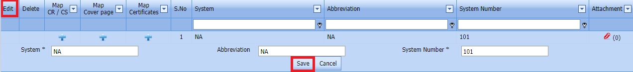
1.1.2 Edit a System
If you want to edit any existing system in the System page,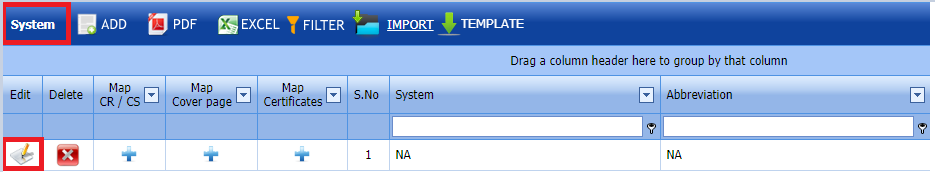
Fig 1.1.2 Edit a System Page
- Click
 (Edit icon) of the respective System. Fig See 1.1.2
The System page shows the details of the selected system.
-
Edit the details of system,Abbreviation and System number as required.
-
Click Save. System updated successfully.


1.1.3 Delete a System
If you want to delete any existing system in the System page, you can use  (Delete icon) provided in the System page. By click confirm delete
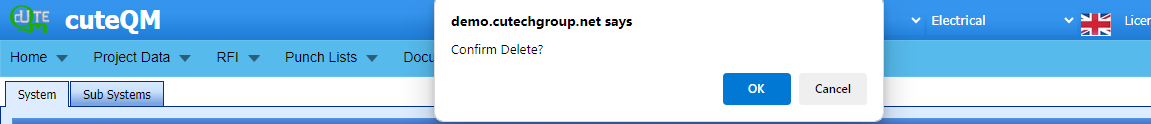
Fig 1.1.3 Delete a System Page
-
Click
 (Delete icon) for the corresponding area.
You receive a Alert message “Confirm Delete?”.
- Click OK. System deleted successfully.

1.1.4 Export in System List
You can export a list of systems added in the System page in both the pdf and excel formats by using (PDF button) and
  (Excel button). Fig See 1.1.4 page
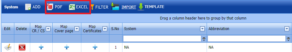
Fig 1.1.4 Export System List Page
1.1.5 Filter a System
If you want to filter any specific system in the System page, you can use  (FILTER button) located on the System page.
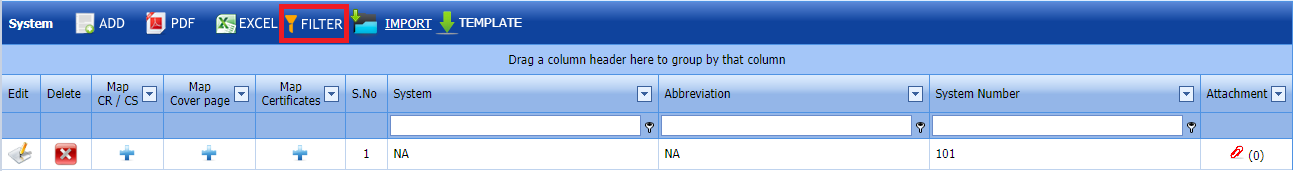
Fig 1.1.5 Filter a System Page
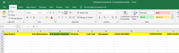
1.1.6 Import Multiple Systems
If you want to import multiple systems together, do the following,
- Click
 (TEMPLATE button). See Fig 1.1.6
An excel worksheet will be downloaded with a predefined template to enter the details of systems.
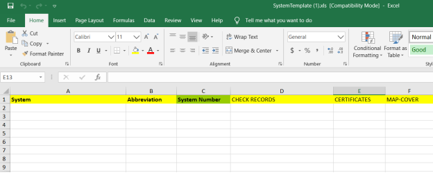
- Enter the required system details in the respective columns of the excel worksheet.
- Once you have added the system details in the excel worksheet, save the excel worksheet on your computer.
-
Click
 (IMPORT button). See Fig
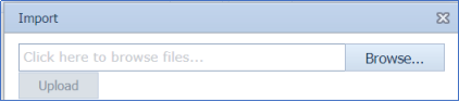
 A new window opens for importing the excel worksheet saved on your computer.

-
Click
 (Browse button) to select the excel worksheet to be uploaded.
 -
Select the excel worksheet you want to upload from your computer.
-
Click
 (Upload button) to export the systems that are included in the excel worksheet.


The details of the systems in the worksheet will be displayed in the System page.
1.1.7 Attach a File into a System
If you want to attach any file with any system listed in the System page, you can attach the file by using  (Attach icon) in the Attachment column.
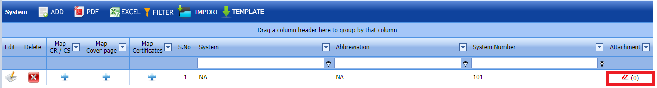
1.2 Sub Systems
The Sub Systems tab in the Project Data menu helps you to add the details of sub systems to be in used in the Electrical Project. If you want to navigate to Sub Systems,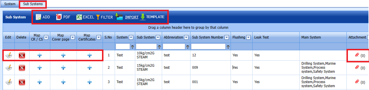
Fig 1.2 Sub System Page.
1.2.1 Add a Sub System
If you want to add a new sub system, do the following steps,
Click  (ADD button) in the Sub System page. See Fig 1.2.1
A new window opens to add a new sub system.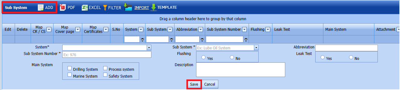
Fig 1.2.1 Add a Sub System Note: The fields notified with a symbol (*) are mandatory. You must enter the relevant details in that fields before saving.
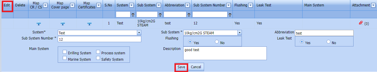
1.2.2 Edit a Sub System
If you want to edit any existing sub system in the Sub System page,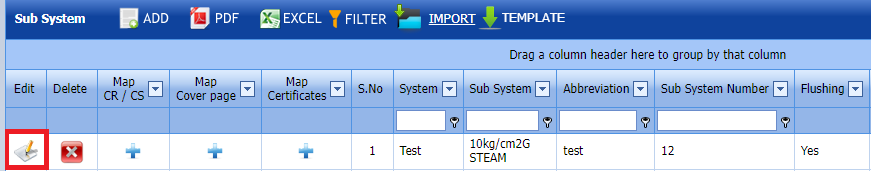
Fig 1.2.2 Edit a Sub System
-
Click
 (Edit icon) of the respective sub system. See Fig 1.2.2
The Sub System page shows the details of the selected sub system.
- Edit the details of system,subsystem,abbreviation and sub system number as required.
-
Click Save.

1.2.3 Delete a Sub System
If you want to delete any existing sub system in the Sub System page, you can use  (Delete icon) provided in the Sub System page.
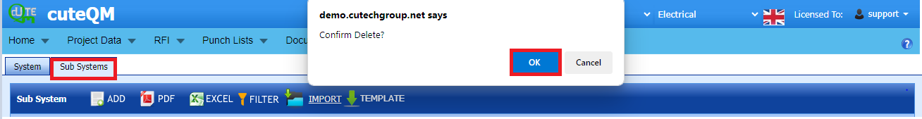
-
Click
(Delete icon) for the corresponding area.You receive a notification message “Confirm Delete?”.
- Click OK.
Sub System deleted successfully
1.2.4 Import a Multiple Sub Systems
If you want to import multiple sub systems together, do the following,
Click  (TEMPLATE button). See Fig 1.2.4
An excel worksheet will be downloaded with a predefined template to enter the details of sub systems.
-
Enter the required sub system details in the respective columns of the excel worksheet.
- Once you have added the sub system details in the excel worksheet, save the excel worksheet on your computer.
- Click
 (IMPORT button). See Fig 1.2.4
A new window opens for importing the excel worksheet saved on your computer.

- Click
 (Browse button) to select the excel worksheet to be uploaded.
 - Select the excel worksheet you want to upload from your computer.
-
Click
 (Upload button) to export the sub systems that are included in the excel worksheet.
 The details of the sub systems in the worksheet will be displayed in the Sub System page.


1.2.5 Attach a File into a Sub System
If you want to attach any file with any sub system listed in the Sub System page, you can attach the file by using  (Attach icon) in the Attachment column.
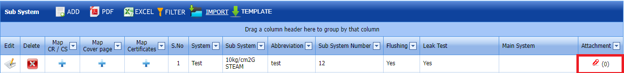
1.3 Cabel Master
The Cabel Master tab in the Project Data menu helps you to add the details of cable master to be in used in the Electrical Project. If you want to navigate to Cabel Master, 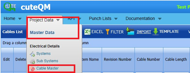
Fig 1.3 Cable Master Page
1.3.0 Cabel List
The Cabel List tab in the Project Data menu helps you to add the details of Cabel List to be in used in the Electrical Project. If you want to navigate to Cabel list.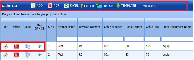
Fig 1.3.0 Cable List Page
1.3.1 Add a Cabel List
If you want to add a new cable list, do the following steps,
Click (ADD button) in cable list page. See Fig 1.3.1
A new window opens to add a new cable list.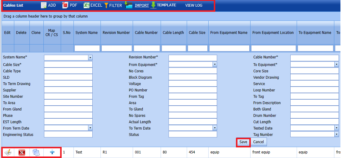
Fig 1.31 Add Cable List Page
-
 Note: The fields notified with a symbol (*) are mandatory. You must enter the relevant details in that fields before saving.
 - In the System Name box, select a system name from a drop-down list.
-
In the Revision No box, select a system no from the drop-down list.
-
In the Cable No box, enter the cable number.
- In the Cable Length box, select a system name from a drop-down list.
-
In the Cabel Size box, enter the cable size number.
- in the From Equipment box, select a system name from a drop-down list.
- In the To Equipment box, select a system name from a drop-down list.
-
Click Save.

The Cable List is successfully added.
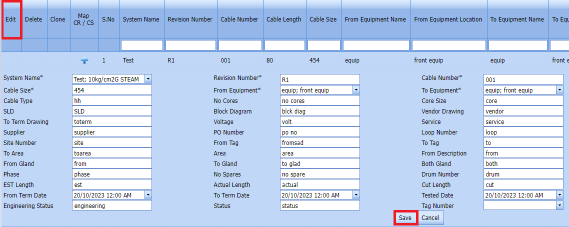
1.3.2 Edit a Cable List
If you want to edit any existing Cable List in Edit Cable List page, do the following,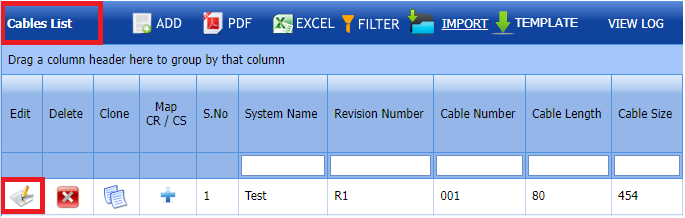
Fig 1.3.2 Edit a Cable List
- Click
 (Edit icon) in the Edit column for the respective cable list. See Fig 3.3.
A new window opens to edit the cable list.

-
Click any box where you want to edit the details, and then edit the details in the respective box.
-
Click Save. The Cable List is successfully updated.

1.3.3 Delete a Cable List
If you want to delete any specific Cable List from the list of cable list, you can use (Delete icon) provided in the  Delete column of the Cable List page,
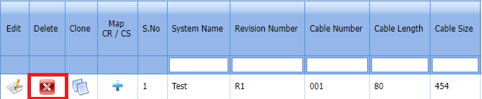
-
Click
 (Delete icon) for the corresponding master drawing.
You receive a notification message “Confirm delete?”.
-
Click OK. The Cable List is successfully deleted.

1.3.4 Clone a Cable list
The Clone option provided in the Cable master page used to add a new clone from previously added clone. If a clone to be added
is having the same specifications of any clone already listed in the clone page, you can add the new clone by using  (Clone icon).
1. Click (Clone icon) of the respective Clone.
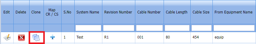
2. If you want to change any details, you can change in the respective boxes.
3. Click Save
The new clone is successfully added and listed in the Clone page.
1.3.5 Add a Map CR/CS
If you want to map CR/CS, do the following steps, Note: If you want to map cover page for any added system, click the respective
  (Add icon) provided in the Map Cover Page column and add the cover pages.
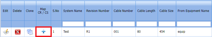
Fig 1.3.5 Add a Map CR/ CS Page
-
If you want to map certificates for any added cable master, click the respective (Add icon) provided in the Map Certificates column and add the cover pages.
-
If you want to map Check Record/Check Sheet (CR/CS) for any added cable master, click the respective (Add icon) provided in the Map CR/CS column and add the cover pages.
1.3.6 Export a Cable List
You can export a list of cable added in the cable page in both the pdf and excel formats by using (PDF button) and (Excel button).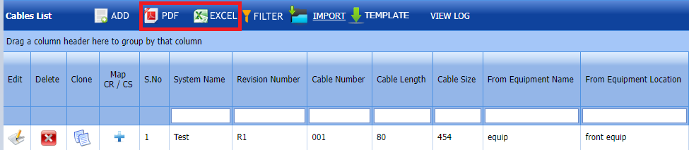
1.3.7 Filter a Cable List
If you want to filter any specific Cable list in the Cable master page, you can use (FILTER button) located on the Cable list page.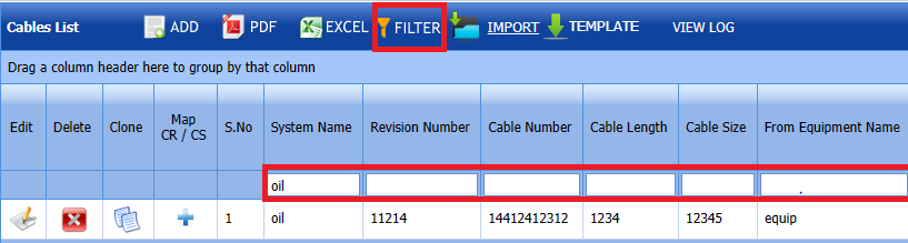
1.3.7 Import Multiple Cable list
If you want to import multiple cable list together, do the following,
-
Click
 (TEMPLATE button).
 An excel worksheet will be downloaded with a predefined template to enter the details of cable no.

-
Enter the required cable no details in the respective columns of the excel worksheet.
-
Once you have added the cable list details in the excel worksheet, save the excel worksheet on your computer.
-
Click
 (IMPORT button).
A new window opens for importing the excel worksheet saved on your computer.
-
Click
 (Browse button) to select the excel worksheet to be uploaded.
 - Select the excel worksheet you want to upload from your computer.
-
Click
 (Upload button) to export the cable list that are added in the excel worksheet.
The details of the cable list in the worksheet will be displayed in the cable list page.


1.4 Type
The Type tab in the Project Data (Electrical) menu helps you add the type details.
If you want to navigate to Type List,
1. Click Type List in the Project Data (Electrical) menu.
The Type List page opens. Fig 1.4 Type Page
1.4.1 Add a Type
If you want to add a new type, do the following steps,
1. Click (ADD button) in the type of page. See Fig 1.4.1
A new window opens to add a new Type 
Fig 1.4.1 Add A Type Page
-
 Note: The fields notified with a symbol (*) are mandatory. You must enter the relevant details in that fields before saving.
 - In the Type box, enter the type .
- In the Description box, enter the description for the type.
- Click Save.
The type is successfully added.

1.4.2 Edit a Type
If you want to edit any existing type in the type of page,
Fig 1.4.2 Edit Page
-
Click
 (Edit icon) of the respective valve.
The Type List page shows the details of the selected type.
- Edit the details of Type and description as required.
- Click Save.
- The type is successfully updated.


1.4.3 Delete a Type
If you want to delete any specific Type from the list of Type you can use (Delete icon) provided in the Delete column of the Type page, 
-
Click
(Delete icon) for the corresponding type.You receive a notification message “Confirm delete?”.

-
Click OK.
- The type is successfully deleted.

1.4.4 Export a Type
You can export a list of Type added in the Type List page in both the pdf and excel formats by using  (PDF button) and
  (Excel button).
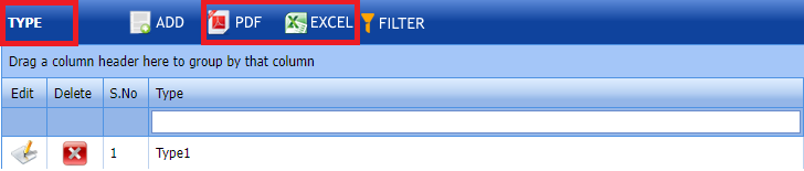
1.4.5Filter a Type
If you want to filter any type in the Type List page, you can use  (FILTER button) provided on the Type List page.
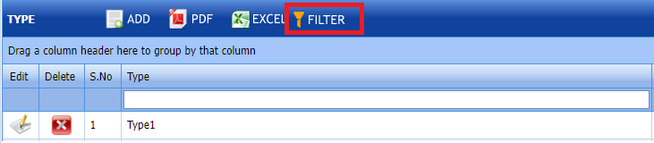
1.5 Equipements List
The Equipements tab in the Project Data menu used to add the details of equipment to be used in the Electrical project. To add equipment,
1. Click Equipements List in the Project Data menu.
The Equipements page opens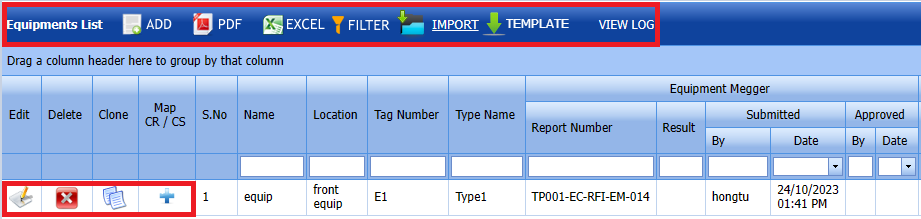
Fig 1.5 Equipements List
1.5.1 Add an Equipment
If you want to add an equipment list, do the following steps,
1. Click  (ADD button) in the Equipements List See Fig 1.5.1
A new window opens to add an equipment List.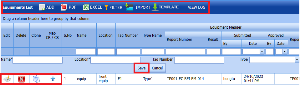
Fig 1.5.1 Add an Equipment List
-
 Note: The field notified with a symbol (*) is mandatory. You must enter the relevant details in that fields before saving.
 -
In the Name box, enter the name of the equipment list.
- In the Location box, enter the location of the equipment list.
- In the Tag Number box, enter the number of the equipment list.
- In the Type box, select the type of the equipment list.
- Click Save.
The equipment list is successfully saved.

1.5.2 Edit an Equipment List
If you want to edit any existing an equipment in the Equipment List page,
Fig 1.5.2 Edit an Equipment List
1. Click  (Edit icon) of the respective test equipment. See Fig 1.5.2
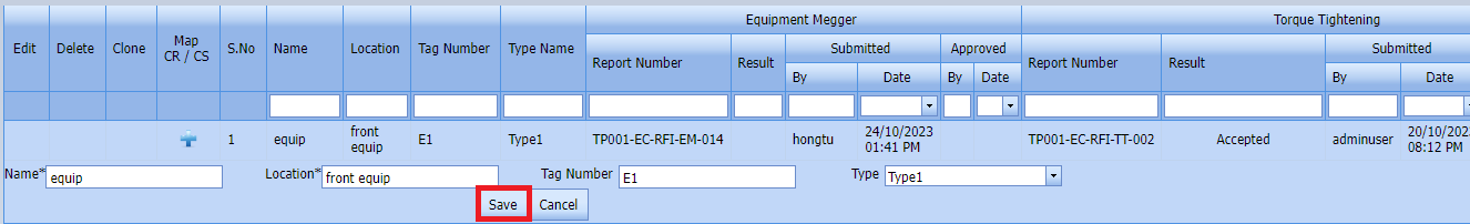
2. Edit the details of equipment name,location,tag number and type as required where you want.
3. Click Save.
The equipment list is successfully updated.
1.5.3 Delete an Equipment List
If you want to delete any existing an equipment list in the Equipment list page, you can use  (Delete icon) provided in the Equipment List page.
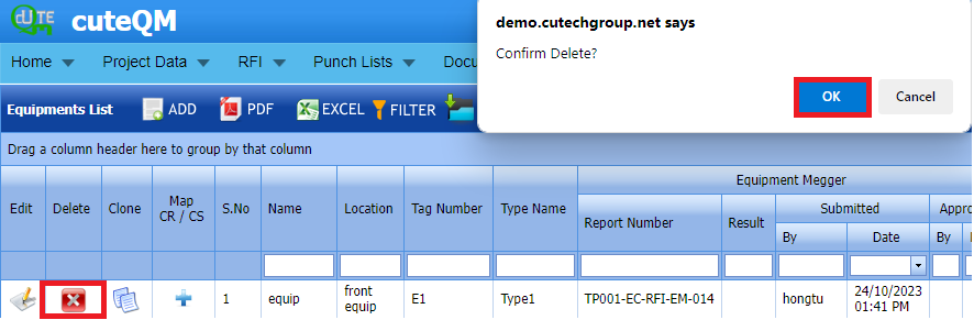
-
Click
(Delete icon) for the corresponding Equipment.You receive a confirmation message “Confirm delete?”.
- Click OK . Selected Equipment List deleted successfully.
1.5.4 Clone an Equipment List
1. Click(Clone icon) of the respective Clone.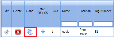
Fig 1.5.4 Clone an Equipment List
2. If you want to change any details, you can change in the respective boxes. 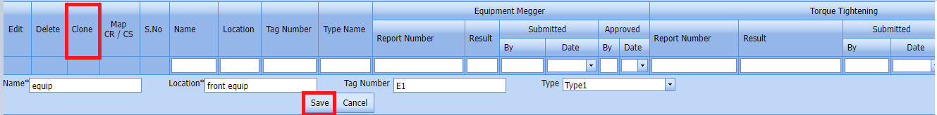 3. Click Save
The new clone is successfully added and listed in the Clone Equipment list page.
1.5.5 Add a Map CR/CS
If you want to add a new Map, do the following steps,

Note: If you want to map cover page for any added equipment click the respective (Add icon) provided in the Map Cover Page column and add the cover pages.
-
If you want to map certificates for any added equipment master, click the respective (Add icon) provided in the Map Certificates column and add the cover pages.
-
If you want to map Check Record/Check Sheet (CR/CS) for any added equipment master, click the respective (Add icon) provided in the Map CR/CS column and add the cover pages.
1.5.6 Export an Equipment List
You can export a list of test equipment list added in the Equipment List page in both the pdf and excel formats by using  (PDF button) and
  (Excel button).
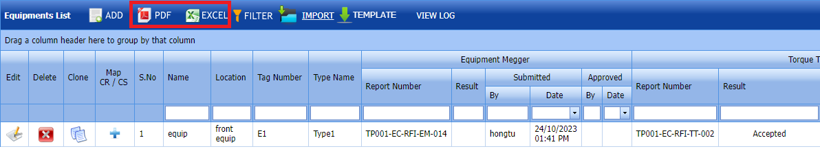
1.5.7 Filter an Equipment List
You can also use  (FILTER button) located on the Equipment list.
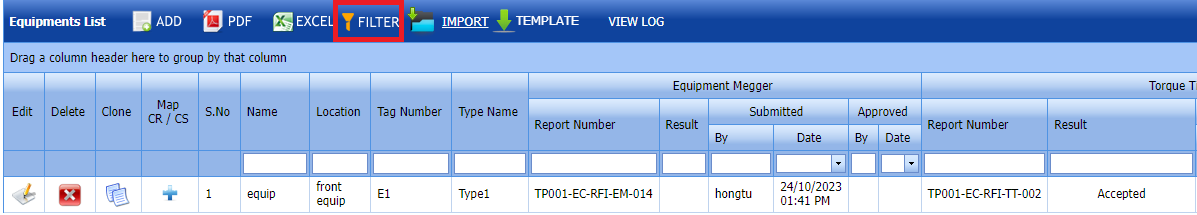
1.5.8 Import Multiple Equipment List
If you want to import multiple equipment list together, do the following,
-
Click
 (TEMPLATE button). See Fig1.5.8
 -
An excel worksheet will be downloaded with a predefined template to enter the details of equipment list.
- Enter the required equipment details in the respective columns of the excel worksheet.
-
Once you have added the equipment details in the excel worksheet, save the excel worksheet on your computer.
-
Click
 (IMPORT button). See Fig 1.5.8
A new window opens for importing the excel worksheet saved on your computer.
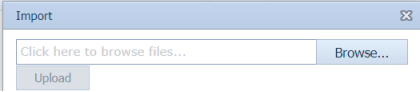
-
Click
 (Browse button) to select the excel worksheet to be uploaded.
 - Select the excel worksheet you want to upload from your computer.
-
Click
 (Upload button) to export the equipment list details that are included in the excel worksheet.
The details of the equipment list in the worksheet will be displayed in the Equipment List page.


1.6 Drawings
Drawing can be added through ADD or import of Drawing Master command.
1. Click Drawing Master in the Project Data menu.
The Drawing Master page opens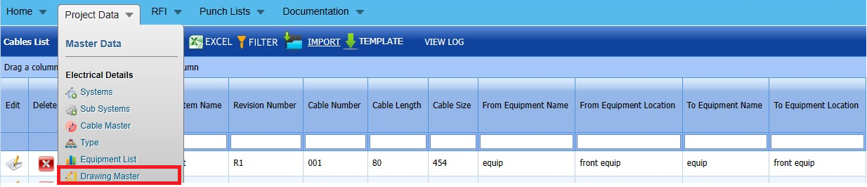
Fig 1.6 Drawing Page
1.6.1 Add a Drawing Master
If you want to Add Drawing Master, do the following steps.
- Click
 (ADD button) in the Drawing type page. See Fig 1.6.1 A new window opens to add a new Drawing Master.
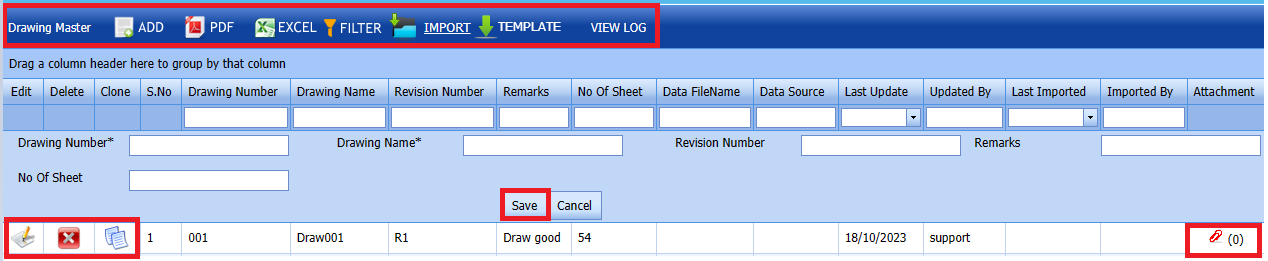
Figure 1.6.1 Drawing Master page. Note: The field notified with a symbol (*) is mandatory. You must enter the relevant details in that fields before saving.
 - In the Drawing Number box, you must enter the drawing number.
- In the Drawing Name box, enter the drawing name.
- In the Revision Number box, enter the revision number.
- Click Save. The Drawing Master is successfully added.


1.6.2 Edit a Drawing Type
If you want to edit any existing Drawing master in the Drawing master page, do the following, steps
- Click
 (Edit icon) in the Edit column for the respective drawing master. See Fig 1.6.2 A new window opens to edit the saved one.
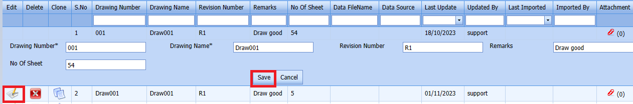
Fig 1.6.2 Edit a Drawing Type - Edit the details of Drawing number,Drawing name,Revision number,No of sheet and remarks as required.
- Click Save. Selected Drawing Master updated successfully.


1.6.3 Delete a Drawing Master
If you want to delete any specific drawing from the drawing master, you can use (Delete icon) provided in the Delete column of the Drawing master page.
-
Click
(Delete icon) for the corresponding Drawing master.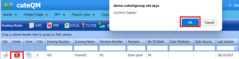
You receive a confirmation message “Confirm delete?”.
- Click OK . Selected Drawing master deleted successfully.

1.6.4 Clone
1. Click(Clone icon) of the respective Clone.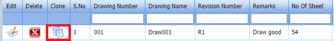
2. If you want to change any details, you can change in the respective boxes.
3. Click Save
The new clone is successfully added and listed in the Clone drawing master page.
1.6.5 Attachments
User can upload multiple documents through attachment screen. 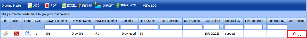
2. It will be redirected to new attachment screen. 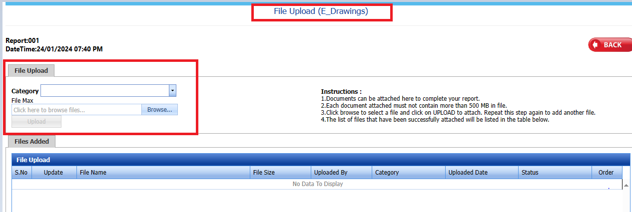
3. Here user can select category of the document and browse & upload the document.
4. Document successfully downloaded
1.6.6 Export a Drawing master list
You can export a list of drawing master list added in the Drawing master List page in both the pdf and excel formats by using (PDF button) and (Excel button).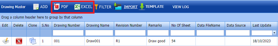
1.6.7 Filter a Drawing Master
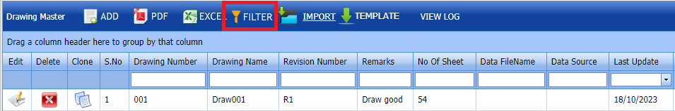 1. Click
  (FILTER button) located on the Drawing Master page.
Once you clicked the Filter button, the filter box opens for the Drawing Number, Drawing Name, Revision number columns. If you want to filter any Drawing master from the list of Drawing master , do the following steps,
1.6.8 Import Multiple Drawing Master
If you want to import multiple Drawing master together, do the following steps,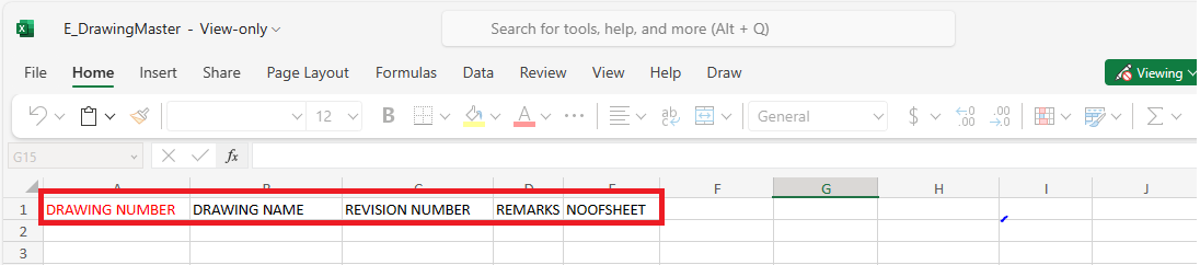
- Click
 (TEMPLATE button). See Fig 1.6.8
 - An excel worksheet will be downloaded with a predefined template to enter the details of Drawing master.
- Enter the required Drawing master and category details in the respective columns of the excel worksheet.
- Once you have added the details in the excel worksheet, save the excel worksheet on your computer.
- Click
 (IMPORT button). See Fig 1.6.8
 - A new window opens for importing the excel worksheet saved on your computer.
- Click
 (Browse button) to select the excel worksheet to be uploaded.
 - Click
 (Upload button) to export the drawing master that are included in the excel worksheet.


Imported successfully. The details of the Drawing master in the worksheet will be displayed in the Drawing master page.
1.7 Tags
1. Click Tags in the Project Data menu.
The Tags page opens.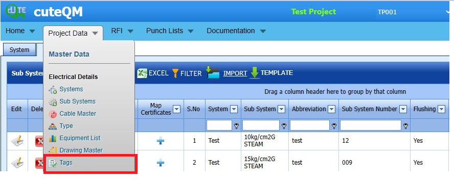
Fig 1.7 Tags Page
1.7.1 Add a Tags
If you want to add a material certificate, do the following,
Click  (ADD button) in the Tags See Fig 1.7.1
A new window opens to add a Tags.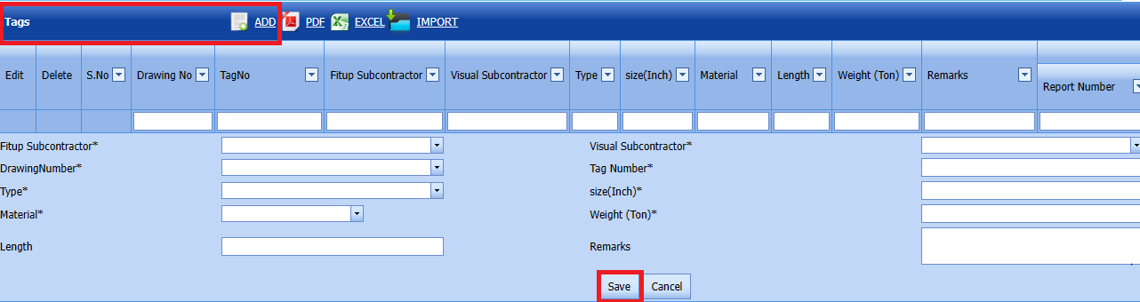
Fig 1.7.1 Add Tags Page
-
 Note: The field notified with a symbol (*) is mandatory. You must enter the relevant details in that fields before saving.
 - In the Fit up Subcontractor box, select the component from a drop-down list.
- In the Visual Subcontractor box, select the number from the drop-down list.
- In the Drawing Number box, select the number from the drop- down list.
- In the Tag number box, enter the Tag number.
- In the Type box, select the type from the drop-down list.
-
In the Size box enter the size.
- In the Material box, select the number from the drop-down list
- In the Weight box, enter the weight number.
- In the Length box, enter the Length number.
- In the Remarks, enter the remarks iif any.
- Click Save.
The Tags is successfully saved.

1.7.2 Edit a Tags
Fig 1.7.2 Edit a Tags
If you want to edit any existing Tags in the Tags page,
-
Click
 (Edit icon) of the respective test equipment. See Fig
 The Tags page shows the details of the selected Tags.
-
Edit the details of Fitup subcontractor,visual subcontractor,Drawing number,Tag number,type,size,material,weight,length and remarks as required.
-
Click Save.
-
Tags is successfully updated.
1.7.3 Delete a Tags
If you want to delete any existing tags in the Tags page, you can use
 (Delete icon) provided in the Tags page.
-
Click
(Delete icon) for the corresponding Tags.You receive a confirmation message “Confirm delete?”.
- Click OK . Selected Tags is deleted successfully.
1.7.4 Export a Tag
You can export a list of Tags added in the Tags page in both the pdf and excel formats by using (PDF button) and
  (Excel button).
-


1.7.5 Import Multiple Tags
If you want to import multiple Tags together, do the following,
Click  (IMPORT button).
The Excel Import page opens. 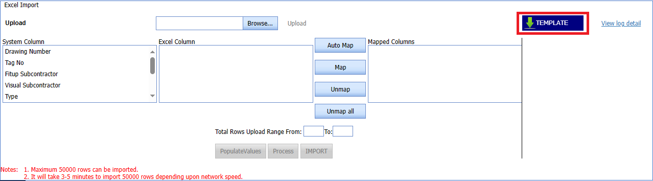
1. Click  (TEMPLATE button).
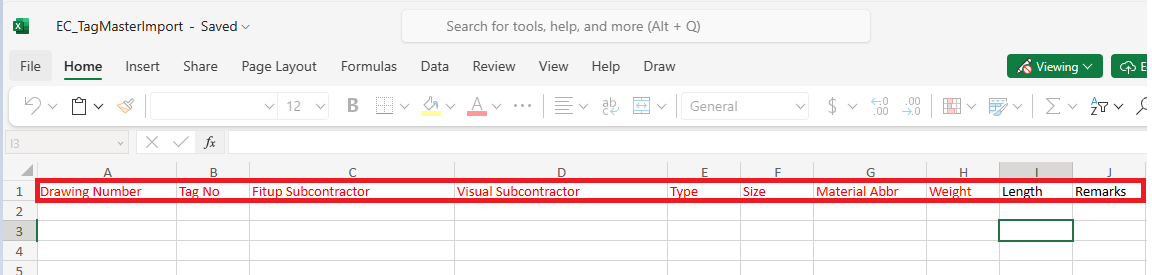
- An excel worksheet will be downloaded with a predefined template to enter the details of Tags.
- Enter the required Tags details in the respective columns of the excel worksheet.
- Once you have added the Tags details in the excel worksheet, save the excel worksheet on your computer.
- Click
 (Browse button) to select the excel worksheet to be uploaded.
 - Select the excel worksheet you want to upload from your computer.
- Click
 (Upload button) to export the Tags details that are included in the excel worksheet.
 -
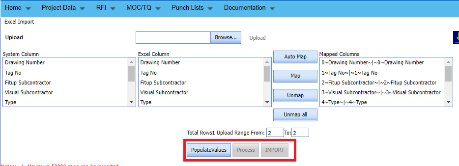
- Automap -This function is used to map system columns and excel columns automatically.
- Map - This function is used to map each system and excel columns manually
- Unmap - This is used to remove the mapped column
- Unmap all -This is used to remove the all mapped columns
- Click populate values ,process and Import buttons.

- Tags imported successfully.


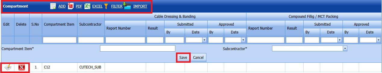
1.8 Compartment
1. Click Compartment in the Project Data menu.
The Compartment page opens. 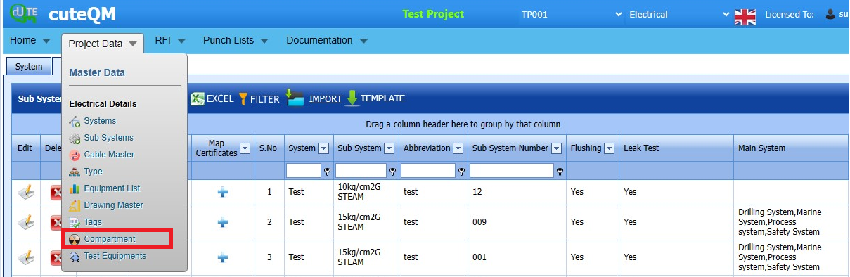
Fig 1.8 Compartment Page
1.8.1 Add a Compartment
If you want to add a material certificate, do the following,
-
Click
 (ADD button) in the Compartment See Fig 1.8.1
A new window opens to add a compartment.

Fig 1.8.1 Add a Compartment Page-
Note: The field notified with a symbol (*) is mandatory. You must enter the relevant details in that fields before saving.
- In the Compartment Item box, enter the compartment item.
- In the Subcontractor box, select the subcontractor from the drop-down list.
- Click Save.
The Compartment is successfully added.
 Note: You can edit and delete the added Compartment by using the respective
  (Edit icon) and
  (Delete icon).
 -


1.8.2 Export a Compartment
You can export a list of drawing master list added in the compartment page in both the pdf and excel formats by using (PDF button) and (Excel button). See Fig 1.8.2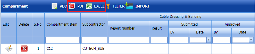
1.8.3 Filter a Compartment
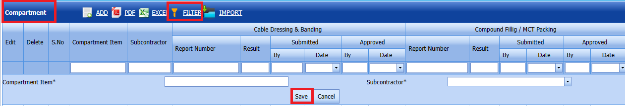
1. Click (FILTER button) located on the compartment page.
Once you clicked the Filter button, the filter box opens for the Compartment Item, Subcontractor columns. If you want to filter any compartment from the list of Compartment, do the following steps,
2. Click Save.
1.8.4 Import Multiple Compartments
If you want to import multiple Compartments together, do the following,
Click (IMPORT button). See Fig 1.8.4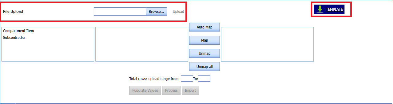
The Excel Import page opens. 
1. Click (TEMPLATE button).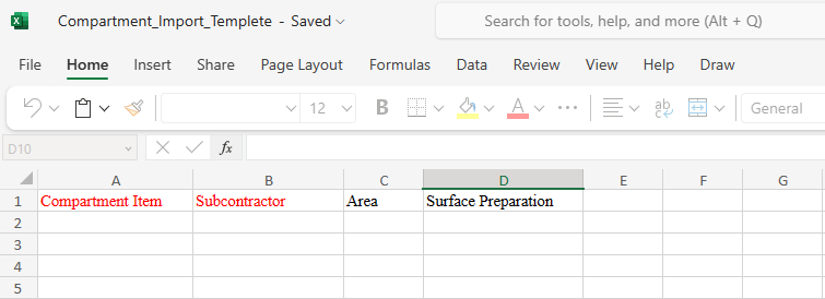
- An excel worksheet will be downloaded with a predefined template to enter the details of Compartment Item.
- Enter the required compartment item details in the respective columns of the excel worksheet.
- Once you have added the compartment item details in the excel worksheet, save the excel worksheet on your computer.
- Click (Browse button) to select the excel worksheet to be uploaded.
- Select the excel worksheet you want to upload from your computer.
- Click (Upload button) to export the Tags details that are included in the excel worksheet.
- Automap -This function is used to map system columns and excel columns automatically.
- Map - This function is used to map each system and excel columns manually
- Unmap - This is used to remove the mapped column
- Unmap all -This is used to remove the all mapped columns
- Click populate values ,process and Import buttons.
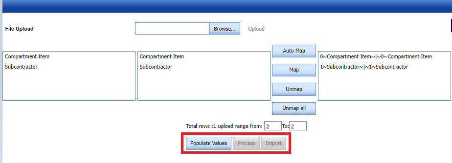
- Compartment imported successfully.

1.9 Test Equipment
The Test Equipment's tab in the Materials menu used to add the details of a test equipment to be used in the Electrical project. To add a test equipment,
1. Click Test Equipment's in the Materials menu.
The Testing Equipment's page opens.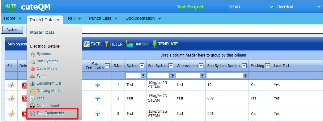
Fig 1.9 Test Equipment Page
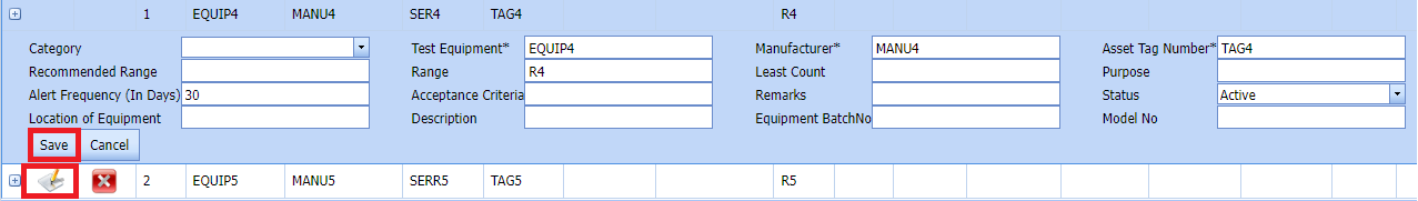
1.9.1 Add a Test Equipment
If you want to add a test equipment, do the following steps,
Click (ADD button) in the Testing Equipment's See Fig 1.9.1
A new window opens to add a test equipment.
Fig 1.9.1 Add a Test Equipment Page
-
Note: The field notified with a symbol (*) is mandatory. You must enter the relevant details in that fields before saving.
-
In the Category box, enter the category of the test equipment.
- In the Test Equipment box, enter the name of the test equipment.
- In the Manufacturer box, enter the name of the manufacturer.
- In the Asset Tag Number box, enter the asset tag number of the test equipment.
- In the Recommended Range box, enter the recommended range of test equipment.
- In the Range box, enter the actual range of test equipment.
- In the Least Count box, enter the least count of the test equipment.
- In the Purpose box, enter the purpose of the test equipment.
-
In the Alert Frequency (in Days) box, the alert frequency duration will be updated automatically. If you want to change the duration you can change.
- In the Acceptance Criteria box, enter the acceptance criteria.
- In the Remarks box, enter your remarks if any.
- In the Status box, select the status of the test equipment.
- In the Location of Equipment box, enter the equipment location detail.
- In the Description box, enter the description for the test equipment.
- In the Equipment Batch no box, enter the equipment batch no location detail.
- In the Model No box, enter the model no.
- Click Save.
The test equipment is successfully saved.
1.9.2 Edit a Test Equipment
If you want to edit any existing test equipment in the Testing Equipment page,
-
Click
(Edit icon) of the respective test equipment. The Testing Equipment page shows the details of the selected test equipment.

Fig 1.9.2 Edit a Test Equipment Page -
Edit the details where you want.
-
Click Save.
1.9.3 Delete a Test Equipment
If you want to delete any existing test equipment in the Testing Equipment page, you can use (Delete icon) provided in the Testing Equipment page. See Fig 1.9.3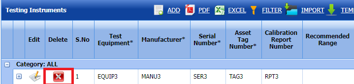
- Click (Delete icon) for the corresponding Test Equipment
Selected deleted Test Equipment successfully.
1.9.4 Export Test Equipment list
You can export a list of test equipment's added in the Test Equipment page in both the pdf and excel formats by using (PDF button) and (Excel button). See Fig 1.9.4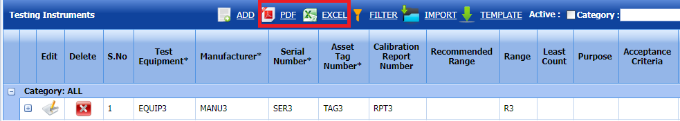
1.9.5 Filter a Test Equipment
If you want to filter any specific test equipment in the Testing Equipment page, See Fig 1.9.5
-
you can use the category wise filter box
 provided in the upper side of the Testing Equipment To filter the testing equipment, select the category from the drop-down list.
 -
you can also use
 (FILTER button) located on the Testing Equipment.
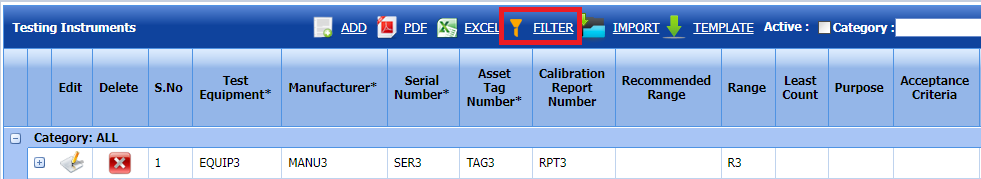


1.9.6 Import Multiple Test Equipements
If you want to import multiple test equipment together, do the following,
-
Click
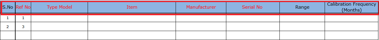
(TEMPLATE button). See Fig 1.9.6An excel worksheet will be downloaded with a predefined template to enter the details of test equipments.

- Enter the required test equipment details in the respective columns of the excel worksheet.
-
Once you have added the test equipment details in the excel worksheet, save the excel worksheet on your computer.
-
Click
(IMPORT button). See Fig 1.9.6A new window opens for importing the excel worksheet saved on your computer.
-
Click
(Browse button) to select the excel worksheet to be uploaded. - Select the excel worksheet you want to upload from your computer.
-
Click
(Upload button) to export the test equipment details that are included in the excel worksheet.The details of the test equipment's in the worksheet will be displayed in the Testing Equipment page.
1.9.7 Attach a File into a Test Equipment
If you want to attach any file with any existing test equipment listed in the Testing Equipment page, you can attach the file by using  (Attach icon) in the Attachment column.
2.0 RFI
2.1 RFI Glanding and termination List
The RFI Glanding and termination List up Request tab allows you add an RFI Glanding and termination request to check the fit-up quality of pipes and joints used in the piping project by a sub-contractor. To navigate to the RFI Glanding and Termination List up request adding page.
1. Click RFI Glanding and Termination List in the RFI menu.
The RFI Glanding and Termination page opens. 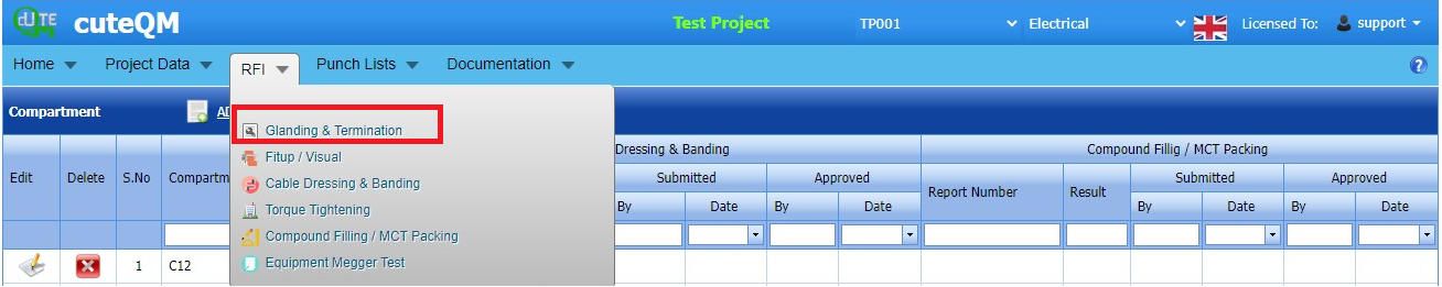
Fig 2.0 RFI Glanding and Termination List
2.1.1 Add a RFI Glanding and Termination request.
If you want to add an RFI Glanding and Termination request, do the following steps,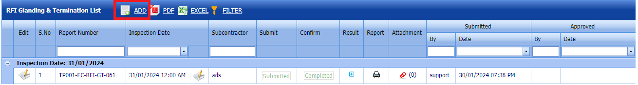
Fig 2.1.1 Add a RFI Glanding & Termination List
-
cuteQM_Production role user only can add a RFI request
- Click add button.Refer fig.2.1.1 above
-
In the Inspection Date and Time box, select the inspection date and time.
- In the Subcontractor box, select a subcontractor from a drop-down list.
- In the Calibration details box, select a calibration detail from a drop-down list.
Before saving the added RFI Glanding & Termination request, you must add joints for the for the RFI Glanding and termination list request.
 Note: You can add multiple cables for one request.
Click (Add Selected Cables) of the respective joints you want to add.
The added cables will be moved and listed in the right side of the page. 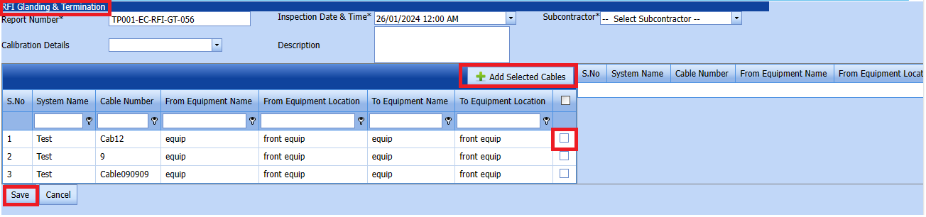
The added cable will be moved and listed in the right side of the page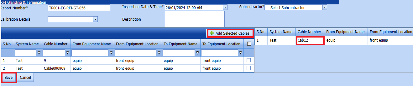
-
 Tip: If you want to remove any added joint, click
  (Remove icon) of the respective joint.
 - In the Description box, enter the description for the added RFI Glanding & Termination request.
- Click Save.
- RFI Glanding & Termination Request created successfully.


2.1.2 Edit a RFI Glanding & Termination List
If you want to edit any existing RFI Glanding & Termination request in the RFI glanding & Termination list page, do the following,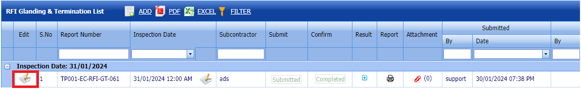
Fig 2.1.2 Edit a RFI Glanding & Termination Page
Click (Edit icon) in the Edit column for the respective RFI Glanding & Termination List. See Fig 2.1.2
The RFI Glanding & Termination list page opens with the details of the selected RFI Glanding & Termination list.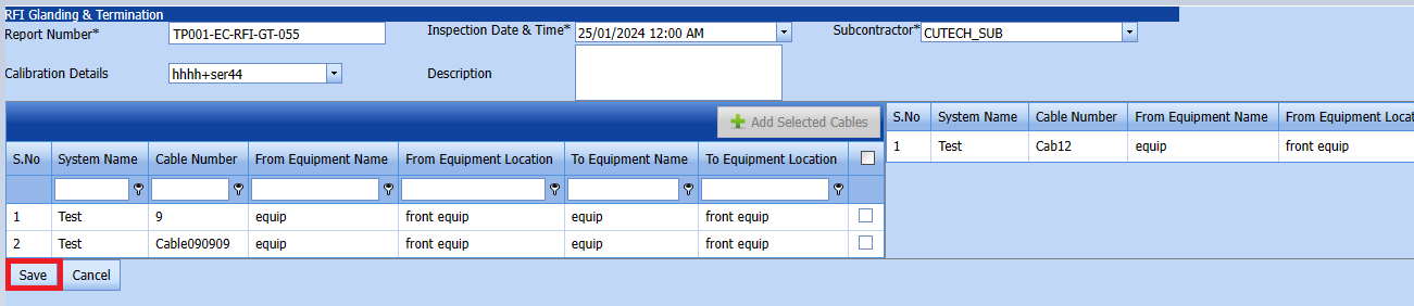
- Click any box where you want to edit the details, and then edit the details in the respective box.
Click Save. - RFI Glanding & Termination Request updated successfully.
2.1.3 Submit a RFI Glanding & Termination List
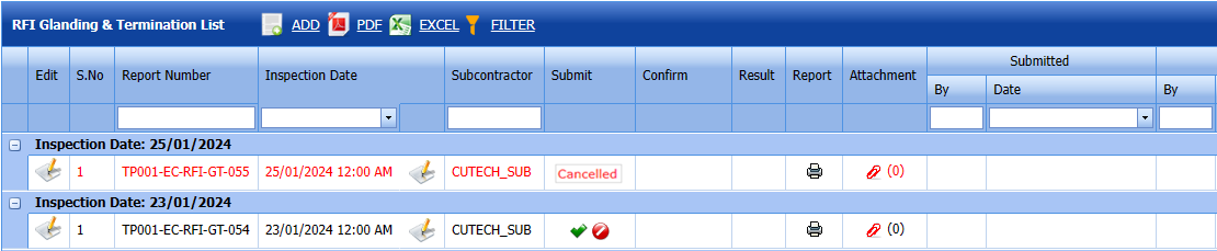
Fig 2.1.3 Submit a RFI Glanding and Termination List
Once you have added the RFI Glanding & Termination list request list, the Submit column in the RFI Glanding & Termination Requests List page is appeared  with (Submit and Reject icons).
- If you want to submit the RFI Glanding & Termination list request, click
 (Submit icon) in the Request Status Otherwise click
  (cancel icon) to cancel the request.


The submitted request will be moved to for RFI Glanding & Termination list inspection.
2.1.4 Approve a RFI Glanding & Termination List
cuteQM_Licensee_QA user only can approve the RFI request.
- If you want to approve the RFI Glanding & Termination list request, click (confirm icon) in the Request Status Otherwise click (Reject icon) to reject the request.
2. Once RFI request approved icon will be enabled to put result.
3. Click icon  result popup will open. Refer below fig
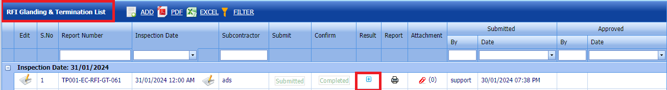
4. User can update the result (Accept/Reject) and Description,L1,L2,L3,Remarks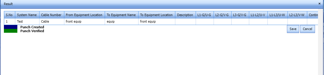
Fig 2.1.4 Approve a RFI Glanding & Termination List - Click Save.
- RFI result is updated successfully.
- If Accepted with comments selected then punch list will be created, and this will be shown in view punch list screen.
- If need to upload documents against equipment's, then click attachment icon at the result popup and upload documents.


2.1.5 View a RFI Glanding & Termination List Report
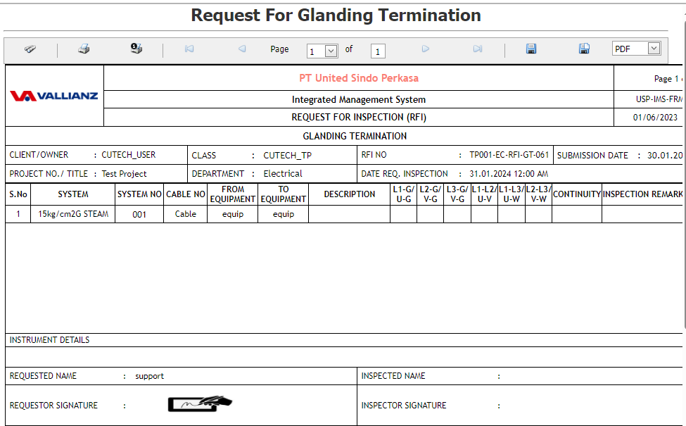
If you want to view an RFI Glanding & Termination report, click  (print icon) provided in the Result column of the RFI Glanding & Termination List page.
In the print, user can see the signature of both the production user and QC . Requestor signature mapped with Production and Inspector signature mapped with QC
Click here to find the steps to upload Digital signature
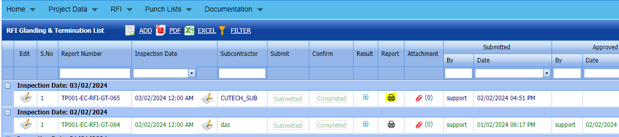
Fig 2.1.5 View a RFI Glanding and Termination List

2.1.6 Attach a File into an RFI Glanding & Termination list.
If you want to attach a file with any existing RFI glanding & termination listed in the RFI Glanding & Termination List page, you can attach the file by using  (Attach icon) in the Attachment column.
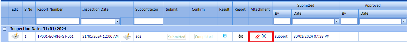
2.1.7 Export a RFI Glanding & Termination Request
You can export a list of RFI glanding & Termination requests added in the RFI Glanding & Termination Requests List page in both the pdf and excel formats by using  (PDF button) and
  (Excel button).
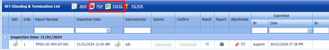
Fig 2.1.7 Export a RFI Glanding & Termination List
2.1.8 Filter a RFI Glanding & Termination Request
If you want to filter any specific RFI glanding and termination in the RFI glanding and termination List page, 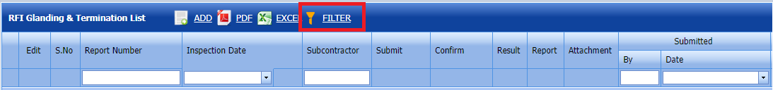
- you can use the filter box provided in the upper side of the RFI Glanding & Termination List To filter the any specific RFI Glanding and Termination request, select the Report Number, Inspection Date and Date in the boxes and click.
- you can use
 (FILTER button) located on the RFI Glanding & Termination List.

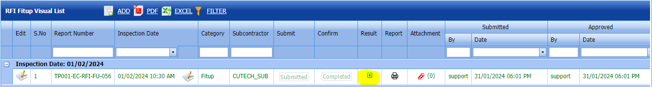
2.2 RFI Fit up/ Visual List
The RFI Fit up/ Visual List tab allows you add an RFI fit up/ Visual List to check the fit-up quality of pipes and joints used in the piping project by a sub-contractor. To navigate to the RFI fit up / Visual List adding page,
Click RFI Fit up Request in the RFI menu.
The RFI Fit up / Visual list page opens. 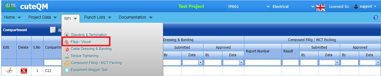
Fig 2.2 RFI Fit up / Visual Page
2.2.1 Add a RFI Fit up/ Visual List
If you want to add an RFI fit up / Visual list, do the following steps,
cuteQM_Production role user only can Add a RFI request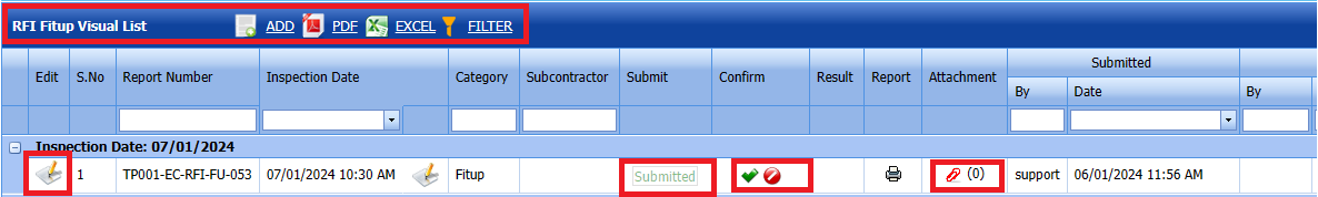
Fig 2.2.1 Add a RFI Fit up / Visual List
- Click
 (ADD button) in the RFI fit up / Visual List page.
A new page opens to add an RFI fit up / Visual request. 
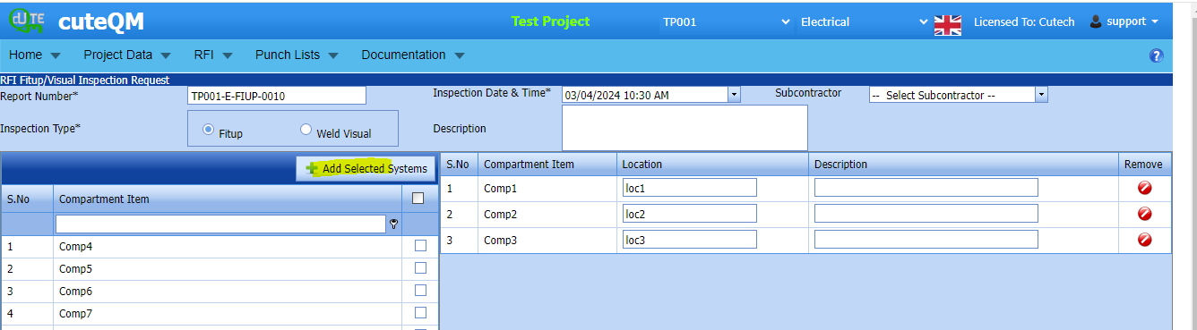


-
In the Inspection Date and Time box, select the inspection date and time.
- In the Subcontractor box, select a subcontractor from a drop-down list.
- In the Inspection Type box, choose an inspection type from given list.
Before saving the added fit up request, you must add joints for the fit-up / visual list request.
Note: You can add multiple System for one request.Click
 (Add Selected System) of the respective system you want to add.
The added compartment will be moved and listed in the right side of the page.
-
Tip: If you want to remove any added system, click (Remove icon) of the respective joint.
- In the Description box, enter the description for the added RFI fit up request.
- Click Save.
The RFI fit up / visual list request is successfully added.
2.2.2 Edit a RFI Fit up / Visual Request
If you want to edit any existing RFI fit up request in the RFI Fit up / Visual list page, do the following,
Click (Edit icon) in the Edit column for the respective RFI fit up request. See Fig 2.2.2
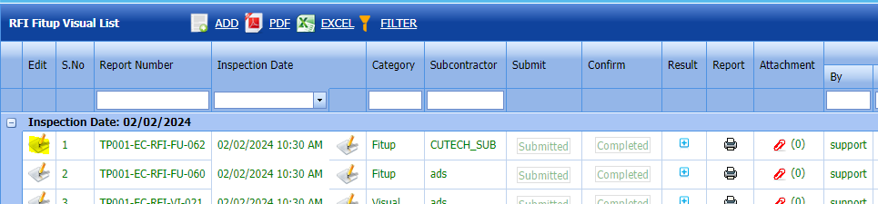
The RFI Fit up Visual list page opens with the details of the selected RFI fit up visual page list.
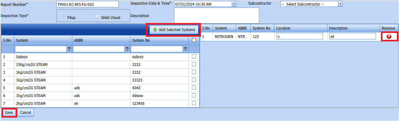
Fig 2.2.2 Edit a RFI Fit up / Visual Page
- Click any box where you want to edit the details, and then edit the details in the respective box.
- Click Save.
2.2.3 Submit an RFI Fit up Request.
Once you have added the RFI fit up request, the Submission column in the RFI Fit up visual Lists page is appeared with (Submit and Reject icons). See Fig 2.2.3
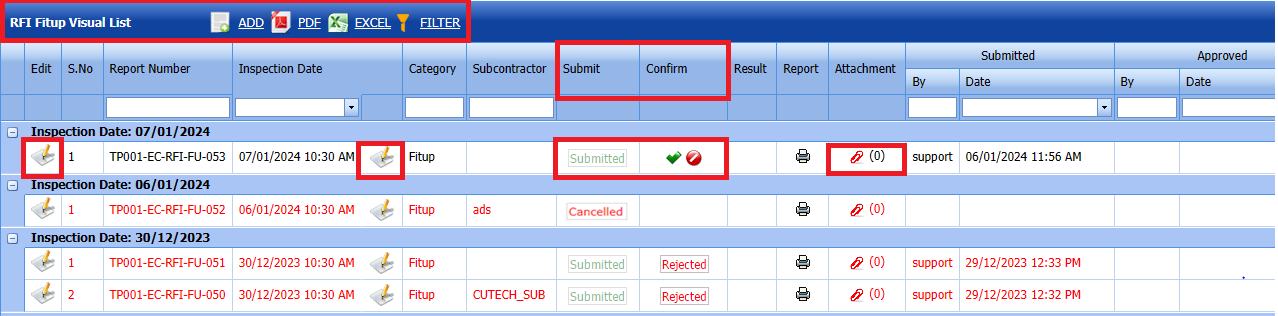
Fig 2.2.3 Submit & Approve a RFI Fit up / Visual Page
-
If you want to submit the RFI fit up request, click
 (Submit icon) in the Submit column. Otherwise click
  (Reject icon) to reject the request.
Once you have submitted the RFI fit up visual list request, in the Confirm Status column in the RFI Fit up visual List page is appeared with
 (Confirm and Reject icons).


The approved request will be moved to for inspection.
2.2.4 Approve RFI Fit up visual List
cuteQM_Licensee_QA user only can approve the RFI request.
- If you want to approve the RFI Fit up visual list request, click (confirm icon) in the Confirm Status Otherwise click (Reject icon) to reject the request.
2. Once RFI request approved icon will be enabled to put result.
3. Click icon  result popup will open.
Fig 2.2.4 Approve RFI Fit up / Visual List page.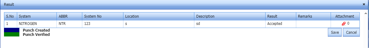
- Click Save
- RFI result is updated successfully.
- If Accepted with comments given as result, then punch list will be created, and this will be shown in view punch list screen.
- If need to upload documents against system No, then click attachment icon at the result popup and upload documents.


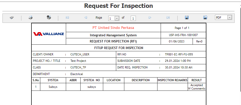
2.2.5 Print a RFI Fit Up / Visual list report.
If you want to view an RFI fit up report, click (print icon) provided in the Report column of the RFI Fit up / Visual page.
In the print, user can see the signature of both the production user and QC . Requestor signature mapped with Production and Inspector signature mapped with QC
Click here to find the steps to upload Digital signature
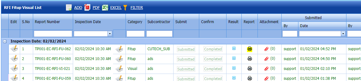
Fig 2.2.5 Print a RFI Fit up / Visual Page

2.2.6 Attach a File into a RFI Fit up Visual List
If you want to attach a file with any existing RFI fit up visual list listed in the RFI Fit up visual List page, you can attach the file by using  (Attach icon) in the Attachment column.
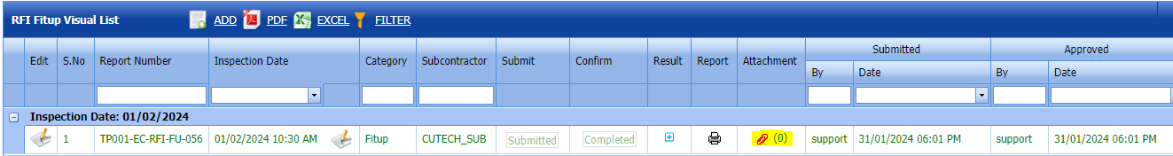
2.2.7 Export a RFI Fit up Visual List
You can export a list of RFI fit up visual list requests added in the RFI Fit up visual List page in both the pdf and excel formats by using (PDF button) and (Excel button).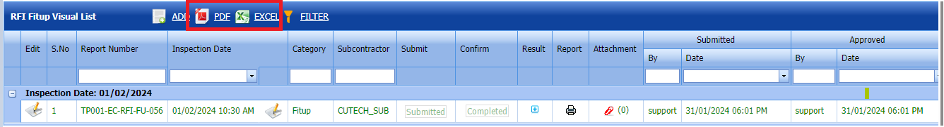
Fig 2.2.7 Export a RFI Glanding & Termination List
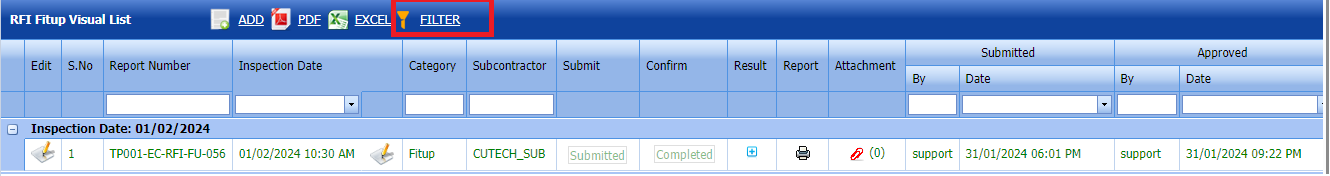
2.2.8 Filter a RFI Fit up Visual List
If you want to filter any specific RFI fit up request in the RFI Fit up Requests List page,
- you can use (FILTER button) located on the RFI Fit up visual List.

2.3 RFI Cable Dressing & Banding Request
Click RFI Cable Dressing & Banding Request in the RFI menu.
The RFI Fit up Requests List page opens. 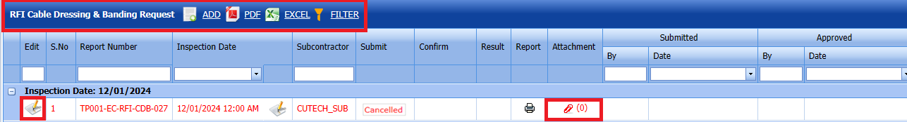
Fig 2.3 RFI Cable Dressing & Banding Request Page
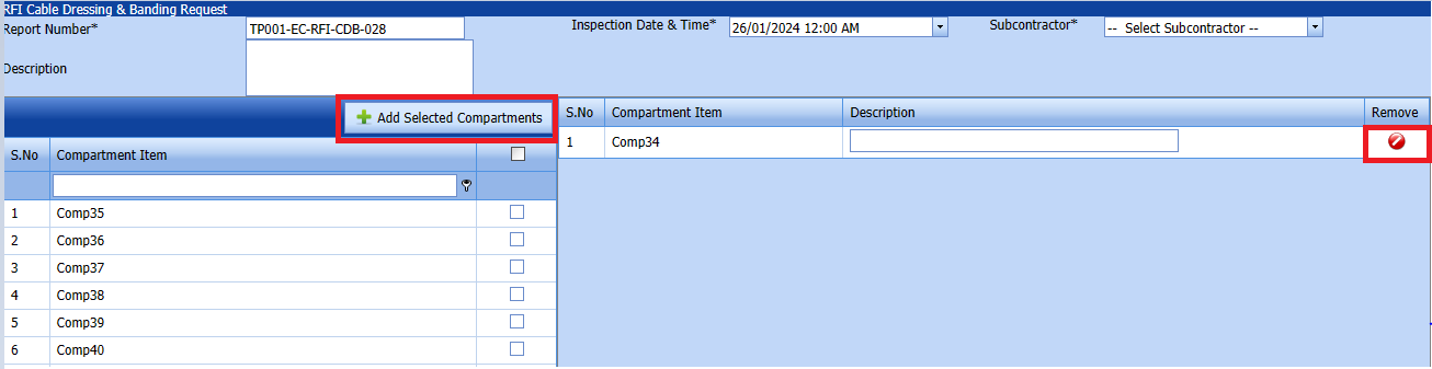
2.3.1 Add a RFI Cable Dressing & Banding Request
If you want to add an RFI Cable Dressing & Banding request, do the following,
cuteQM_Production role user only can Add a RFI request.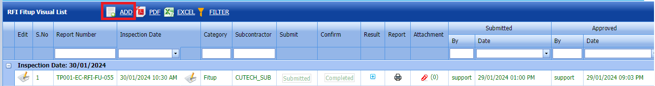
Fig 2.3.1 Add an RFI Cable Dressing & banding request Page
- Click (ADD button) in the RFI Cable dressing & Banding request List page.
A new page opens to add an RFI Cable Dressing & Banding request.
-

-
 Tip: A report number and an RFI number for a new RFI Cable Dressing & Banding request will be updated automatically
 - In the Subcontractor box, select the name of a sub-contractor from a drop-down list.
- In the Inspection Date & Time box, select the date of inspection.
-
In the Description box, enter the description for the inspection.
-
Click the check box of the respective compartments.
-
Click
 (Add Selected Systems button).
 -
Click Save.
-


2.3.2 Submit a Cable Dressing & Banding Request
Once you have added the RFI Cable Dressings, the result column in the RFI Cable Dressing & Banding request page is appeared with(Submit and Reject icons). See Fig 2.3.2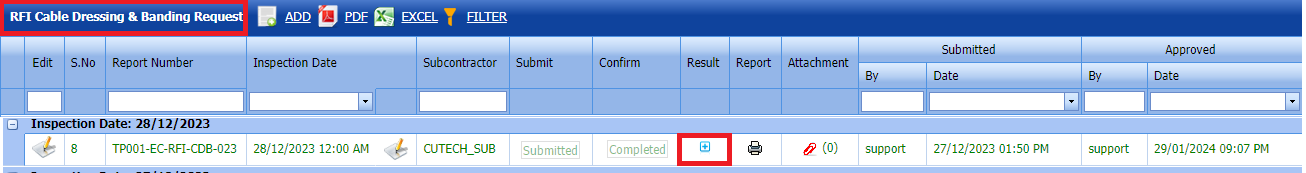
Fig 2.3.2 RFI Cable Dressing & Banding Request Page
-
If you want to submit the RFI fit up request, click
(Submit icon) in the Submit column. Otherwise click (Reject icon) to reject the request.
The submitted request will be moved to for inspection.
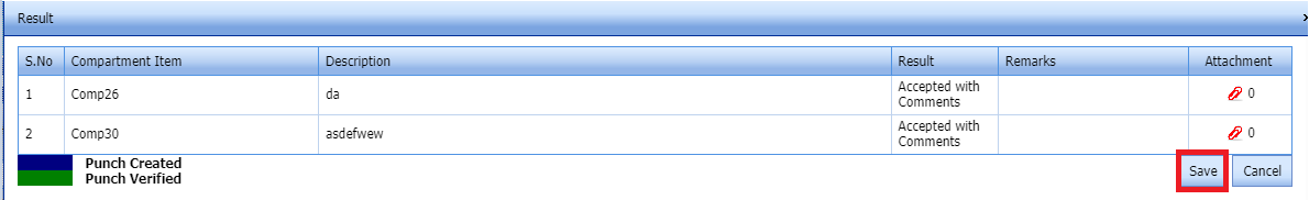
2.3.3 Approve RFI Cable Dressing & banding request List
cuteQM_Licensee_QA user only can approve the RFI request.
- If you want to approve the RFI Cable Dressing & Banding request, click (confirm icon) in the Confirm Status Otherwise click (Reject icon) to reject the request.
2. Once RFI request approved icon will be enabled to put result.

3. Click icon  result popup will open.
Fig 2.3.3 Approve RFI Cable Dressing & Banding request List
- Click Save
- RFI result is updated successfully.
- If Accepted with comments given as result, then punch list will be created, and this will be shown in view punch list screen.
- If need to upload documents against system No, then click attachment icon at the result popup and upload documents.

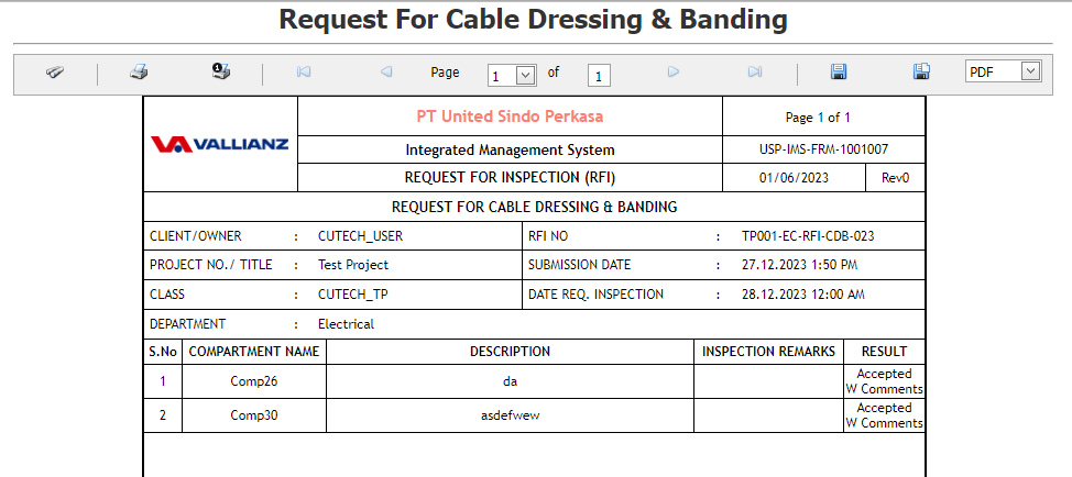
2.3.4 View a RFI Cable Dressing & Banding Report
If you want to view an RFI Cable Dressing & Banding request, click (print icon) provided in the Report column of the RFI Cable dressing & Banding request page. See Fig 2.3.4 View a RFI Cable Dressing & Banding Report
In the print, user can see the signature of both the production user and QC . Requestor signature mapped with Production and Inspector signature mapped with QC
Click here to find the steps to upload Digital signature

2.3.5 Export a RFI Cable Dressing & Banding request List
You can export a list of RFI Cable Dressing & banding list visual list requests added in the RFI Cable Dressing & banding request page in both the pdf and excel formats by using (PDF button) and (Excel button).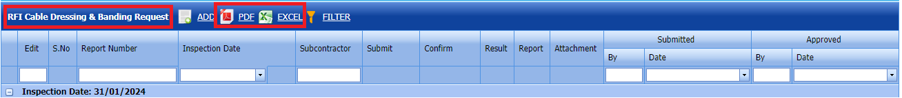 Fig 2.3.5 Export a CabIe Dressing & Banding request Page.
2.3.6 Filter a RFI Cable dressing & Banding request List
If you want to filter any RFI Cable dressing & Banding request from the list of RFI requests in the RFI Cable dressing & Banding request List page, you can use  (FILTER button).
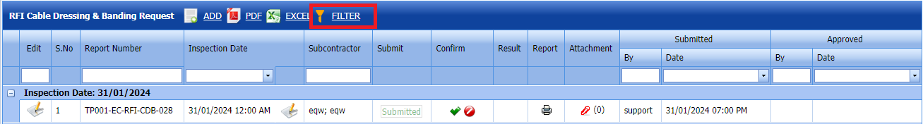
Fig 2.3.6 Filter a RFI Cable Dressing & Banding request Page
2.4 RFI Torque Request
Click RFI Torque Request in the RFI menu.
The RFI Torque Request page opens.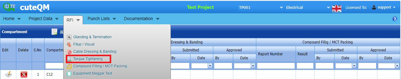
Fig 2.4 Torque Tightening Page
2.4.1 Add a RFI Torque Request
If you want to add an RFI Torque request, do the following steps,
cuteQM_Production role user only can ADD a RFI request.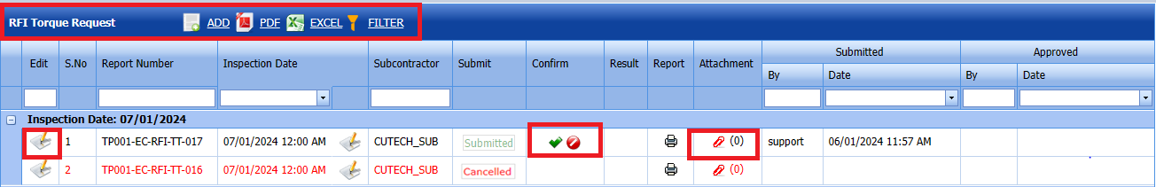
Fig 2.4.1 Add a RFI Torque Request page.
- Click (ADD button) in the RFI Torque request page
A new page opens to add an RFI fit Torque request. 
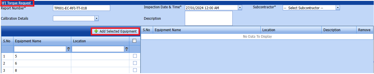

- In the Inspection Date and Time box, select the inspection date and time.
- In the Subcontractor box, select a subcontractor from a drop-down list.
- In the Calibration Details box, select a calibration detail from a drop-down list.
- In the Description box, enter the description for the inspection.
Before saving the added RFI Torque request, you must equipment list request.
 Note: You can add multiple equipment for one request.
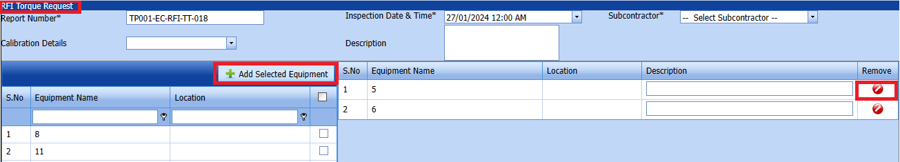
1. Click (Add Selected Equipment) of the respective equipment you want to add.
The added equipment will be moved and listed in the right side of the page.
-
Tip: If you want to remove any added equipment, click (Remove icon) of the respective equipment.
- In the Description box, enter the description for the added RFI Torque request.
- Click Save.
2.4.2 Edit a RFI Torque Request
If you want to edit any existing RFI torque request in the RFI torque request page, do the following,
Fig 2.4.2 Edit a RFI Torque Request Page
Click (Edit icon) in the Edit column for the respective RFI torque request.
The RFI Torque request page opens with the details of the selected RFI torque request page list.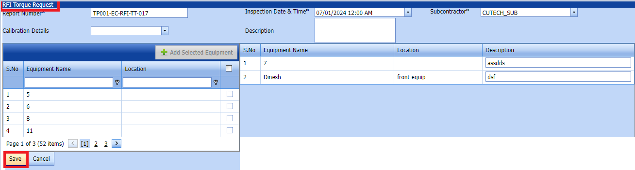
Click Save.
2.4.3 Submit a RFI Torque Request
Once you have added the RFI Cable Dressings, the result column in the RFI torque request page is appeared with(Submit and Reject icons). See Fig 2.4.3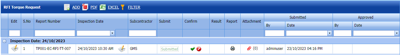
Fig 2.4.3 Submit RFI torque Request Page
-
If you want to submit the RFI torque request, click
(Submit icon) in the Submit column. Otherwise click (Reject icon) to reject the request.Once you have submitted the RFI torque request visual list request, in the Confirm Status column in the RFI Cable Dressing & banding request List page is appeared with
(Confirm and Reject icons).
The submitted request will be moved to for inspection.
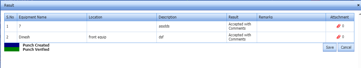
2.4.4 Approve a RFI Torque Request
cuteQM_Licensee_QA user only can approve the RFI request.
- If you want to approve the RFI torque request List page request, click (confirm icon) in the Request Status Otherwise click (Reject icon) to reject the request.
2. Once RFI request approved icon will be enabled to put result.
3. Click icon  result popup will open.
Fig 2.4.4 Approve a RFI torque request List page.
- Click Save.
- RFI result is updated successfully.
- If Accepted with comments givenas result then punch list will be created, and this will be shown in view punch list screen.
- If need to upload documents against equipment's, then click attachment icon at the result popup and upload documents.
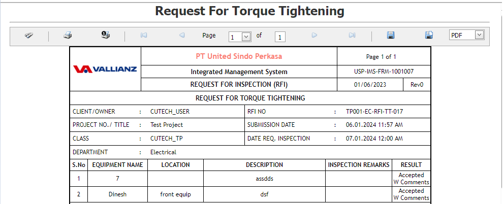
2.4.5 Print a RFI Torque request Report
If you want to view an RFI torque request List page, click (print icon) provided in the Result column of the RFI torque request List page.
In the print, user can see the signature of both the production user and QC . Requestor signature mapped with Production and Inspector signature mapped with QC
Click here to find the steps to upload Digital signature
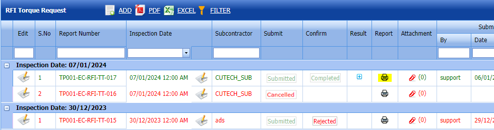
Fig 2.4.5 View a RFI RFI torque request.

2.4.6 Attach a File into an RFI Torque request Result.
If you want to attach a file with any existing RFI Torgue request listed in the RFI torque request List page, you can attach the file by using (Attach icon) in the Attachment column.
2.4.7 Export RFI Torque Request
You can export a list of RFI torque requests added in the RFI Torque Requests List page in both the pdf and excel formats by using (PDF button) and (Excel button).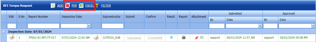
Fig 2.4.7 Export RFI Torque Request Page
2.4.8 Filter an RFI Torque Request
If you want to filter any RFI Torque request from the list of RFI fit up requests in the RFI Torque Requests List page, you can use (FILTER button). 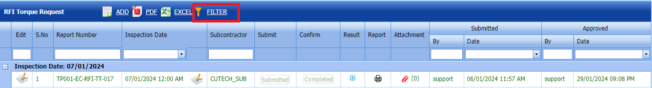
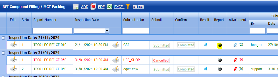
2.5 RFI Compound filling / MCT Packing
Click RFI Compound filling / MCT Packing in the RFI menu.
The RFI compound filling / MCT packing page opens.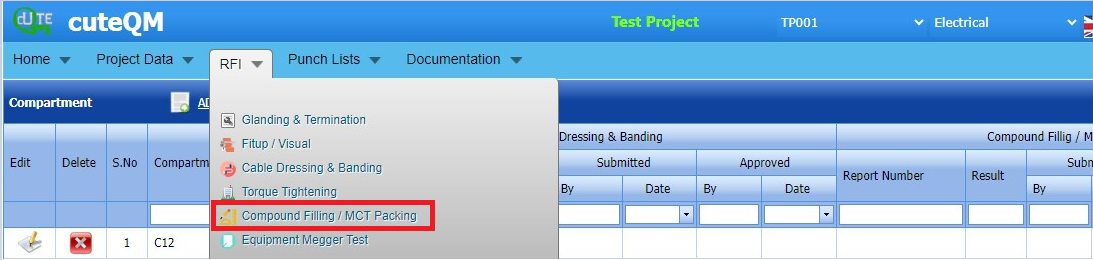
Fig 2.5 RFI Compound Filling / MCT Packing page
2.5.1 Add a RFI Compound filling / MCT Packing
If you want to add an RFI Compounding filling / MCT Packing, do the following steps,
cuteQM_Production role users only can ADD a RFI request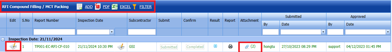
Fig 2.5.1 Add A RFI Compound Filling / MCT packing Page.
- Click (ADD button) in the RFI Compound Filling / MCT Packing page.
A new page opens to add an RFI compound filling / MCT packing request. 

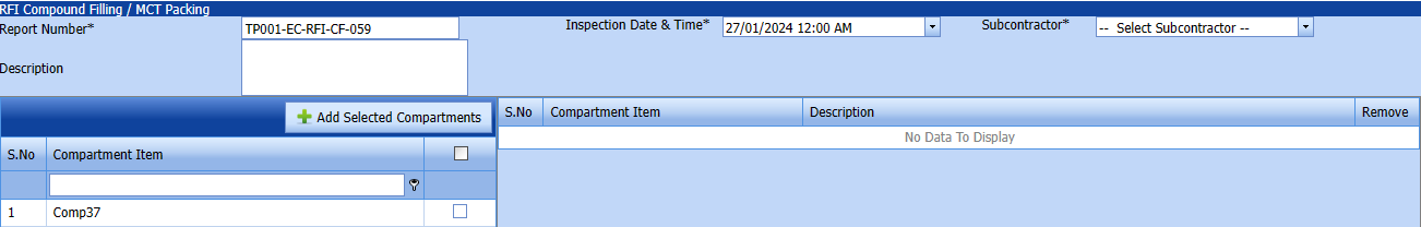
- In the Inspection Date and Time box, select the inspection date and time.
- In the Subcontractor box, select a subcontractor from a drop-down list.
- In the Description box, enter the description for the inspection.
Before saving the added RFI compound filling / MCT Packing, you must add Compartments list request.
Note: You can add multiple compartments for one request.
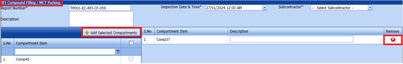
1. Click (Add Selected Compartments) of the respective joints you want to add.
The added compartments will be moved and listed in the right side of the page.
-
Tip: If you want to remove any addedcompartment, click (Remove icon) of the respective joint.
- In the Description box, enter the description for the added RFI fit up request.
- Click Save.
2.5.2 Edit a RFI Compound Filling / MCT Packing
If you want to edit any existing RFI Compound filling / MCT packing request in the RFI Compound filling / MCT packing request page, do the following,
Click (Edit icon) in the Edit column for the respective RFI torque request. 
Fig 2.5.2 Edit a RFI Compound Filling / MCT Packing Page
The RFI Compound Filling / MCT Packing page opens with the details of the selected RFI Compound Filling / MCT Packing page list.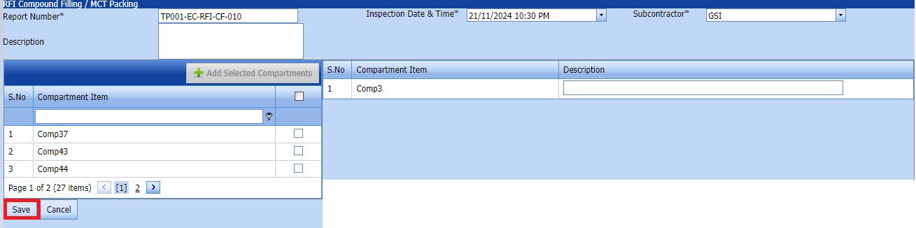
Click Save.
2.5.3 Submit a RFI Compound Filling / MCT Packing
Fig 2.5.3 Submit a RFI Compound Filling / MCT Packing list.
Once you have added the RFI Compound Filling / MCT Packing request list, the Submit column in the RFI Compound Filling / MCT Packing page is appeared with (Submit and Reject icons).
- If you want to submit the RFI Compound Filling / MCT Packing request, click (Submit icon) in the Request Status Otherwise click (cancel icon) to cancel the request.
The submitted request will be moved to for RFI Compound Filling / MCT Packing inspection.
2.5.4 Approve a RFI Compound Filling / MCT Packing
cuteQM_Licensee_QA user only can approve the RFI request.
- If you want to approve the RFI Glanding & Termination list request, click (confirm icon) in the Request Status Otherwise click (Reject icon) to reject the request.
2. Once RFI request approved icon will be enabled to put result.

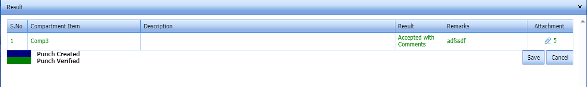
3. Click icon  result popup will open.
4. User can update the result and Description, Remarks
Fig 2.5.4 Approve a RFI Compound Filling / MCT Packing
- Click Save.
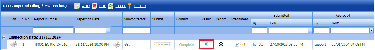
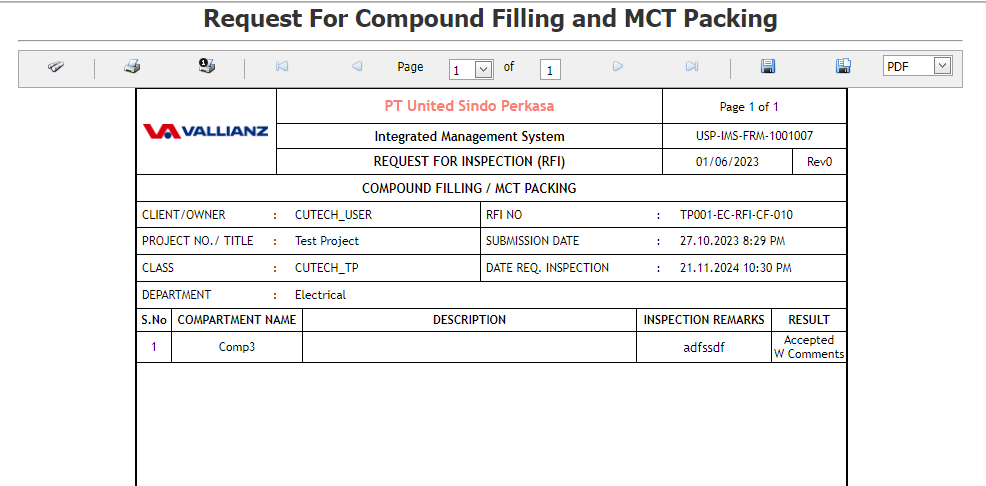
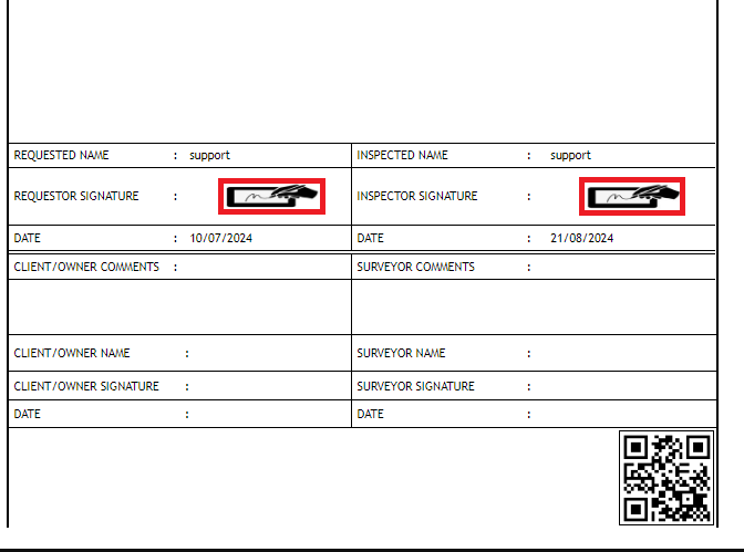
2.5.5Print a RFI Compound Filling / MCT Packing Report
If you want to view an RFI Compound Filling / MCT Packing report, click (print icon) provided in the Result column of the RFI Compound Filling / MCT Packing List page.
In the print, user can see the signature of both the production user and QC . Requestor signature mapped with Production and Inspector signature mapped with QC
Click here to find the steps to upload Digital signature
See Fig 2.5.5 Print RFI Compound Filling/ MCT Packing Report
2.5.6 Attach a File into RFI Compound Filling / MCT Packing
If you want to attach a file with any existing RFI compound filling / MCT Packing requests in the RFI compound filling / MCT Packing requests List page, you can attach the file by using (Attach icon) in the Attachment column. 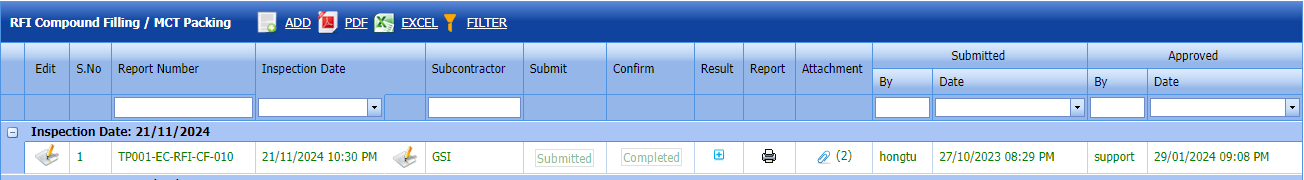 Fig 2.5.6 Attach RFI Compound Filling / MCT Packing Page
2.5.7 Export RFI Compound Filling / MCT Packing
You can export a list of RFI compound filling / MCT Packing requests added in the RFI compound Filling / MCT Packing List page in both the pdf and excel formats by using (PDF button) and (Excel button).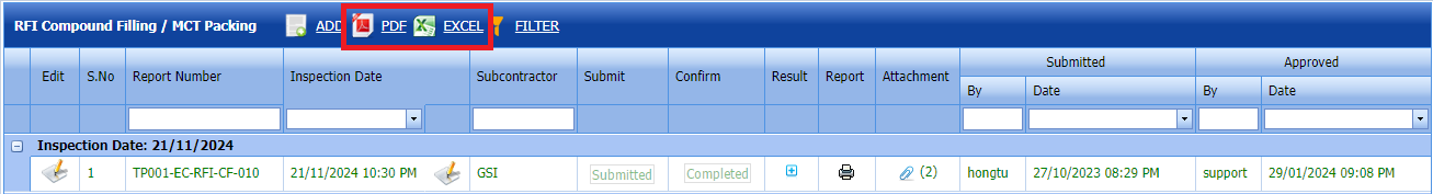
See Fig 2.5.7 Export RFI Compound Filling/ MCT Packing Report
2.5.8 Filter a RFI Compound Filling / MCT Packing
If you want to filter any RFI compound filling / MCT Packing request from the list of RFI compound filling / MCT Packing in the RFI compound filling / MCT Packing List page, you can use (FILTER button). 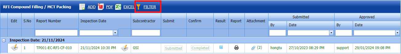
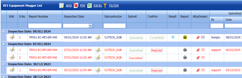
2.6 RFI Equipment Megger List
Click RFI Equipment Megger List in the RFI menu.
The RFI Equipment Megger List page opens.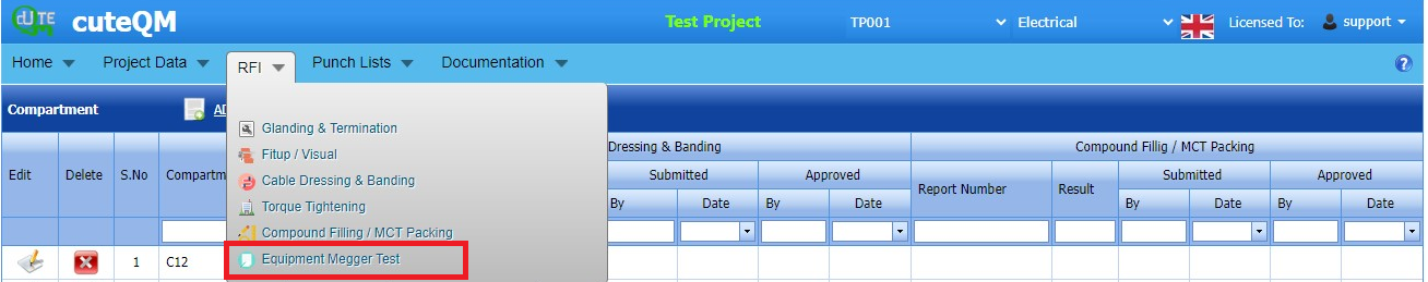 Fig 2.6 RFI Equpment Megger List Page.
2.6.1 Add a RFI Equipment Megger List
If you want to add an RFI Equipment Megger List, do the following steps,
cuteQM_Production user only can ADD a RFI request.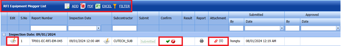
Fig 2.6.1 Add RFI Equipment Megger List Page
- Click (ADD button) in the RFI Equipment Megger List.
A new page opens to add an RFI Equipment Megger request. 
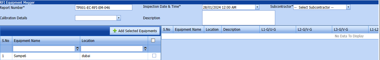

- In the Inspection Date and Time box, select the inspection date and time.
- In the Subcontractor box, select a subcontractor from a drop-down list.
- In the Description box, enter the description for the inspection.
Before saving the added RFI Equipment Megger request, you must add Equipment list request.
Note: You can add multiple Equipment for one request.
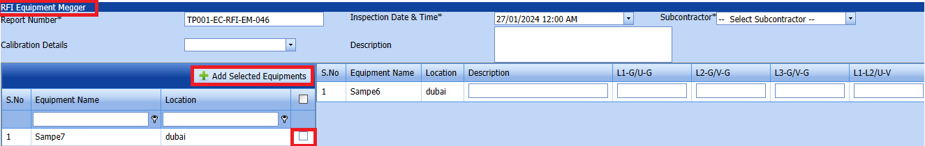
1. Click (Add Selected Equipements) of the respective equipment you want to add.
The added equipment will be moved and listed in the right side of the page.
-
Tip: If you want to remove any added equipments, click (Remove icon) of the respective joint.
- In the Description box, enter the description for the added RFI equipment megger request.
- Click Save.
2.6.2 Edit a RFI Equipment Megger List
If you want to edit any existing RFI Equipment Megger List request in the RFI Equipment Megger request page, do the following,
Fig 2.6.2 Edit RFI Equipment Megger List page.
Click (Edit icon) in the Edit column for the respective RFI Equipment Megger. See Fig 2.6.2
The RFI Equipment Megger page opens with the details of the selected RFI Equipment Megger page list.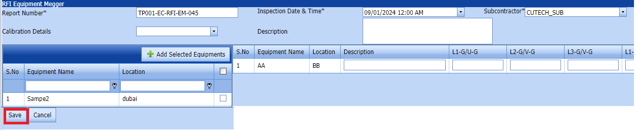
Click Save.
2.6.3 Submit a RFI Equipment Megger List
Fig 2.6.3 Submit a RFI Equipment Megger List
Once you have added the RFI Equipment Megger request list, the Submit column in the RFI Equipment Megger List page is appeared with (Submit and Reject icons).
- If you want to submit the RFI Equipment Megger request, click (Submit icon) in the Request Status Otherwise click (cancel icon) to cancel the request.
The submitted request will be moved to for RFI Equipment Megger inspection.
2.6.4 Approve a RFI Equipment Megger List
cuteQM_Licensee_QA user only can approve the RFI request.
- If you want to approve the Equipment Megger request, click (confirm icon) in the Request Status Otherwise click (Reject icon) to reject the request.
2. Once RFI request approved icon will be enabled to put result.
3. Click icon  result popup will open.
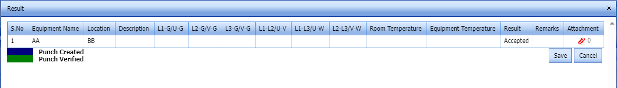
4. User can update the result (Accept/Reject) and Description,L1,L2,L3,Remarks

Fig 2.6.4 Approve a RFI Equipment Megger List page - Click Save.
- RFI result is updated successfully.
- If Acceped with comments given as result then punch list will be created, and this will be shown in view punch list screen.
- If need to upload documents against equipment's, then click attachment icon at the result popup and upload documents.
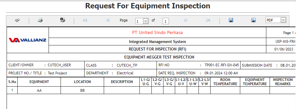
2.6.5 View a RFI Equipment Megger List Report
If you want to view an RFI Equipment Megger, click (print icon) provided in the Result column of the RFI Equipment Megger List page.
In the print, user can see the signature of both the production user and QC . Requestor signature mapped with Production and Inspector signature mapped with QC
Click here to find the steps to upload Digital signature

2.6.6 Attach a File into an RFI Equipment Megger List
If you want to attach a file with any existing RFI Equipment listed in the RFI Equipment Megger List page, you can attach the file by using (Attach icon) in the Attachment column. 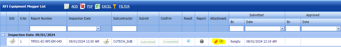
Fig 2.6.6 Attach file RFI Equipment Megger List
2.6.7 Export a RFI Equipment Megger List
You can export a list of RRFI Equipment Megger requests added in the RFI Equipment Megger List page in both the pdf and excel formats by using (PDF button) and (Excel button).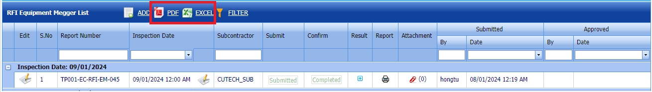
Fig 2.6.7 Export RFI Equipment Megger List
2.6.8 Filter a RFI Equipment Megger List
If you want to filter any RFI Equipment Megge request from the list of RFI Equipment Megge in the RFI Equipment Megger page, you can use (FILTER button). 
Fig 2.6.8 Filter RFI Equipment Megger List.
No Comments