
Project Data
3.0 Project Data
The Project Data menu helps you to add the details of master data and personnel data when you started to do a project. This menu explains all the basic works of structural master drawing, weld map drawing, cutting plan drawing and import joints.
The Project Data menu appears with two options such as Masters and Personnels. The Masters option helps you to add master data for the structural project. The Personnels option helps you to add the details of persons for example welders and inspectors, who are all involved in the structural project.
3.1 Area
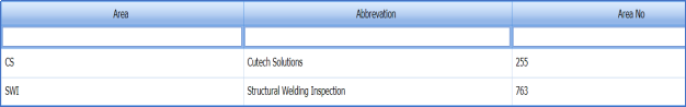
The Area tab in the Project Data menu helps you to add the details of area. If you want to add any area, do the following,
-
Click Area in the Project Data menu.
The Area page opens.
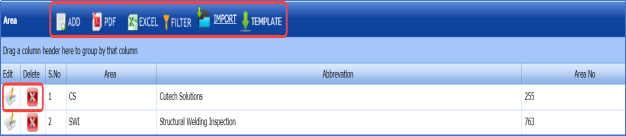
Figure 3.1: Area page

3.1.1 Add an Area
If you want to add an area, do the following,
- Click
 (ADD button) in the Area page. See Fig 3.1.
A new window opens to add an area.
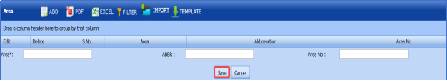
 Note: The field notified with a symbol (*) is mandatory. You must enter the relevant details in that fields before saving.
 - In the Area box, enter the name of an area.
-
In the Abbreviation box, enter the abbreviation for the added area.
-
In the Area No box, enter the area number.
-
Click Save.
The area is successfully added.


3.1.2 Edit Any Area
If you want to edit any existing area in the Area page, do the following,
- Click
 (Edit icon) in the Edit column for the respective area. See Fig 3.1.
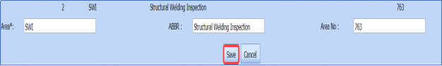
A new window opens to edit the area.
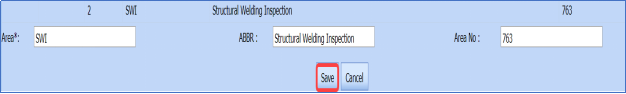
- Click any box where you want to edit the details, and then edit the details in the respective box.
-
Click Save.

3.1.3 Delete Any Area
If you want to delete any specific area from the list of areas, you can use (Delete icon) provided in the Delete column of the Area page, See Fig 3.1.
-
Click
 (Delete icon) for the corresponding area.
You receive a notification message “Do you want to delete?”.
- Click OK.

3.1.4 Export Areas List
You can export a list of areas added in the Area page in the pdf and excel formats.
-
If you want to export the areas list in the pdf format, click
 (PDF button).
 The list will be downloaded in the pdf format.
- If you want to export the areas list in the excel format, click
 (Excel button).
The list will be downloaded in the excel format.


3.1.5 Filter Any Area
If you want to filter any area from the list of areas in the Area page, do the following,
- Click
 (FILTER button) located on the Area page. See Fig 5.1.
Once you clicked the Filter button, the filter box opens for the Area, Abbreviation, and Area No columns.

-
Enter relevant detail in the respective column’s filter box to filter any area.

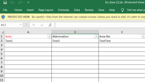
3.1.6 Import Multiple Areas
If you want to import multiple areas together, do the following,
-
Click
 (TEMPLATE button) on the Area page. See Fig 3.1.
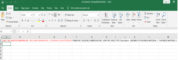
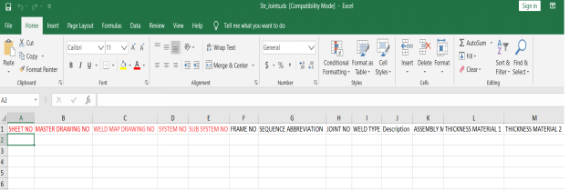
A template will be downloaded as an excel worksheet to enter the details of multiple areas.

-
Enter the relevant details in the required columns on the excel worksheet.
- Once you have added the area details in the excel worksheet, save the excel worksheet on your computer.
-
Click
 (IMPORT button). See Fig 3.1.
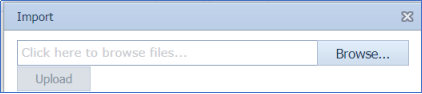
A new window opens for importing the excel worksheet saved on your computer.

-
Click (Browse button) to select the excel worksheet to be uploaded.
-
Select the excel worksheet you want to upload from your computer.
-
Click
 (Upload button) to export the areas that are included in the excel worksheet.


The details of the areas in the worksheet will be displayed in the Area page.
3.2 Client Master Drawings
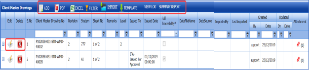
Master drawing is a layout drawing provided to explain about the material such as plate and beam, and the material’s parameters used in the structural project. The Client Master Drawings tab helps you to add the client master drawing details.
If you want to add any client master drawing details, do the following,
- Click Client Master Drawings in the Project Data menu.
The Client Master Drawings page opens.
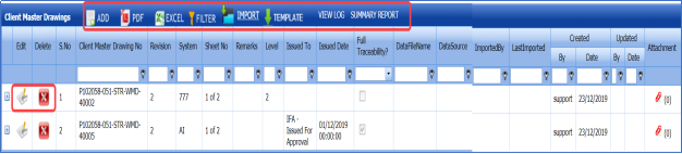
Figure 3.2 Client Master Drawings page
3.2.1 Add a Client Master Drawing
If you want to add a client master drawing, do the following,
- Click
 (ADD button) in the Client Master Drawings page. See Fig 3.2.
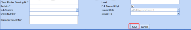
A new window opens to add a client master drawing.

 Note: The fields notified with a symbol (*) are mandatory. You must enter the relevant details in that fields before saving.
 -
In the Client Master Drawing No box, enter the client master drawing number.
-
In the Revision box, enter the revision number.
-
In the Level box, enter the level number of the client master drawing.
-
If you want to enable the full traceability option, click the check box provided with the Full Traceability? column.
-
In the Sub System box, select the system and sub system numbers from a drop-down list.
-
In the Issued Date box, select the issued date of the client master drawing.
-
In the Issued To box, select the purpose of issuing the client mater drawing.
-
In the Sheet Number box, enter the sheet number of the client master drawing.
 Note: The sheet number is nothing but a page number of the master drawing sheet. If the master drawing is provided in single sheet, the Sheet No should be 1 of 1. If the drawing is stretched to two pages, then the Sheet No should be 1 of 2 and 2 of 2.
 -
In the Remarks/Description box, enter your remarks or description if any.
-
Click Save.


The client master drawing is successfully added.
3.2.2 Attach a File into a Client Master Drawing
If you want to attach any file with any client master drawing listed in the Client Master Drawings page,
- Click
 (Attach icon) provided in the Attachment column for the respective client master drawing in the Client Master Drawings page.
The File Upload (Client Master Drawings) page opens.
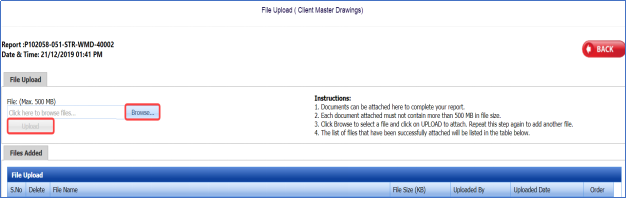
 Note: Before uploading any file, read the instructions given in the File Upload (Client Master Drawings) page.
 - Click
 (Browse button) to select a file to be uploaded.
 -
Select any file which you want to upload, from your computer.
-
Click
 (Upload button) to attach the file.

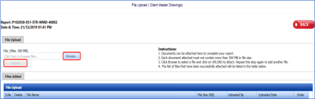


The uploaded file will be displayed in the File Upload table.
3.2.3 Edit Any Client Master Drawing
If you want to edit any existing client master drawing in the Client Master Drawings page, do the following,
- Click
 (Edit icon) in the Edit column for the respective client master drawing. See Fig 3.2.
A new window opens to edit the client master drawing.
-
Click any box where you want to edit the details, and then edit the details in the respective box.
-
Click Save.

3.2.4 Delete Any Client Master Drawing
If you want to delete any specific client master drawing from the list of client master drawings, you can use  (Delete icon) provided in the Delete column of the Client Master Drawings page, See Fig 6.2. To know how to delete, see the topic, “Delete Any Area”.
3.2.5 Export Client Master Drawings List
You can export a list of client master drawings added in the Client Master Drawings page in the pdf and excel formats. To know how to export, see the topic, “Export Areas list” in the Area option.
3.2.6 Filter Any Client Master Drawing
If you want to filter any client master drawing from the list of client master drawings in the Client Master Drawings page, you can use the  (FILTER button). To know how to filter, see the topic, ”Filter Any Area”.
3.2.7 Import Multiple Client Master Drawings
If you want to import multiple client master drawings together, do the following,
- Click
 (TEMPLATE button) on the Client Master Drawings See Fig 3.2.
A template will be downloaded as an excel worksheet to enter the details of client master drawings.

- Enter the relevant details in the required columns on the excel worksheet.
- Once you have added the client master drawing details in the excel worksheet, save the excel worksheet on your computer.
- Click
 (IMPORT button). See Fig 3.2.
A new window opens for importing the excel worksheet saved on your computer.

- Click
 (Browse button) to select the excel worksheet to be uploaded.
 -
Select the excel worksheet you want to upload from your computer.
-
Click
 (Upload button) to export the client master drawings that are included in the excel worksheet.


The details of the client master drawings in the worksheet will be displayed in the Client Master Drawings page.
3.3 Master Drawings
The Master Drawings tab helps you to add the master drawing details. If you want to add any master drawing details, do the following,
-
Click Master Drawings in the Project Data menu.
The Master Drawings page opens.
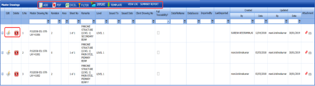
Figure 3.3 Master Drawings page

3.3.1 Add a Master Drawing
If you want to add a master drawing, do the following,
- Click
 (ADD button) in the Master Drawings page. See Fig 3.3.
A new window opens to add a master drawing.
 Note: The fields notified with a symbol (*) are mandatory. You must enter the relevant details in that fields before saving.
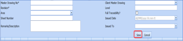
 - In the Master Drawing No box, enter the master drawing number.
-
In the Client Master Drawing box, select the client master drawing from a drop-down list.
-
In the Revision box, enter the revision number.
-
In the Level box, enter the level number of the master drawing.
-
In the Area box, select an area from a drop-down list.
-
If you want to enable the full traceability option, click the check box provided with the Full Traceability? column.
-
In the Sheet Number box, enter the sheet number of the master drawing.
 Note: The sheet number is nothing but a page number of the master drawing sheet. If the master drawing is provided in single sheet, the Sheet No should be 1 of 1. If the drawing is stretched to two pages, then the Sheet No should be 1 of 2 and 2 of 2.
 - In the Issued Date box, choose the issued date of the master drawing.
-
In the Remarks/Description box, enter your remarks or description if any.
-
In the Issued To box, select the purpose of issuing the master drawing, from a drop-down list.
-
Click Save.


The master drawing is successfully added.
3.3.2 Attach a File into a Master Drawing
If you want to attach any file with any master drawing listed in the Master Drawings page, follow the procedures given in the topic “Attach a file into a client master drawing” in the Client Master Drawing section.
3.3.3 Edit Any Master Drawing
If you want to edit any existing master drawing in the Master Drawings page, do the following,
- Click
 (Edit icon) in the Edit column for the respective master drawing. See Fig 3.3.
A new window opens to edit the master drawing.
-
Click any box where you want to edit the details, and then edit the details in the respective box.
-
Click Save.

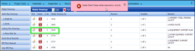
3.3.4 Delete Any Master Drawing
If you want to delete any specific master drawing from the list of master drawings, you can use (Delete icon) provided in the  Delete column of the Master Drawings page, See Fig 3.3.
-
Click
 (Delete icon) for the corresponding master drawing.
You receive a notification message “Do you want to delete?”.
-
Click OK.
 Note: If you receive a notification message “Delete failed! Please delete dependency records.”, you must delete the corresponding weld map drawing for the selected master drawing.
To delete the corresponding weld map drawing,
- Navigate to the Weld Map Drawings tab.
-
Find out the weld map drawing for the respective master drawing.
 Tip: one master drawing has either a single or multiple weld map drawing.
 -
Delete the corresponding weld map drawings.
- Navigate to the Master Drawing tab, and then repeat the steps 1 and 2 to delete the respective master drawing.


3.3.5 Export Master Drawings List
You can export a list of master drawings added in the Master Drawings page in the pdf and excel formats. To know how to export, see the topic, “Export Areas list” in the Area option.
3.3.6 Filter Any Master Drawing
If you want to filter any master drawing from the list of master drawings in the Master Drawings page, you can use the (FILTER button). To know how to filter, see the topic, ”Filter Any Area”.
3.3.7 Import Multiple Master Drawings
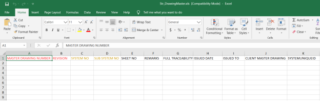
You can import multiple master drawing details together by using a pre-defined excel template given in the application. If you want to import multiple master drawings together, do the following,
- Click (TEMPLATE button) on the Master Drawings page. See Fig 3.3.
A template will be downloaded as an excel worksheet to enter the details of master drawings.

- Enter the relevant details in the required columns on the excel worksheet.
-
Once you have added the master drawing details in the excel worksheet, save the excel worksheet on your computer.
- Click
 (IMPORT button). See Fig 3.3.
A new window opens for importing the excel worksheet saved on your computer.

- Click
 (Browse button) to select the excel worksheet to be uploaded.
 -
Select the excel worksheet you want to upload from your computer.
-
Click
 (Upload button) to export the master drawings that are included in the excel worksheet.


The details of the master drawings in the worksheet will be displayed in the Master Drawings page.
3.4 Weld Map Drawings
Weld map drawing is an isometric drawing that assists in identifying weld joints in the structural project. This drawing also shows areas that will be used for NDT once welding is completed. By using the weld map drawing, the welding cycle and lead times will be reduced accordingly.
If you want to add any weld map drawing details, do the following,
- Click Weld Map Drawings in the Project Data menu.
The Weld Map Drawings page opens.
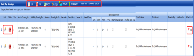
Figure 3.4 Weld Map Drawings page

3.4.1 Add a Weld Map Drawing
If you want to add a weld map drawing, do the following,
- Click
 (ADD button) in the Weld Map Drawings page. See Fig 3.4.
A new window opens to add a weld map drawing.
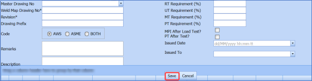
 Note: The fields notified with a symbol (*) are mandatory. You must enter the relevant details in that fields before saving.
 - In the Master Drawing No box, select a master drawing number from a drop-down list.
-
In the Weld Map Drawing No box, enter the weld map drawing number.
-
In the Revision box, enter the revision number.
-
In the Drawing Prefix box, enter the drawing prefix.
- In the Radiographic Testing (RT) Requirement (%) box, enter the required percentage of RT.
- In the Ultrasonic Testing (UT) Requirement (%)box, enter the required percentage of UT.
- In the Magnetic Particle Testing (MT) Requirement (%) box, enter the required percentage of MT.
- In the Dye penetrant inspection(PT) Requirement (%) box, enter the required percentage of PT.
The RT Requirement (%), UT Requirement (%), MT Requirement (%) and PT Requirement (%) should be filled with valid numerical numbers. The joint testing will be performed based on the value given by you for example, if you enter 100 % of requirement, which means 100 % of the joints will be tested. If you enter 0 %, none of joints will be tested.
- If you want to do the magnetic particle inspection after load test, click the check box provided with the Magnetic Particle Inspection (MPI) After Load Test?
-
If you want to do PT after test, click the check box provided with the PT After Test? option.
-
In the code option, select any one from American Welding Society (AWS) or American Society of Mechanical Engineers (ASME) or BOTH.
-
In the Remarks box, enter your remarks if any.
-
In the Issued Date box, choose the issued date of the weld map drawing.
-
In the Issued To box, select the purpose of issuing the weld map drawing, from a drop-down list.
-
In the Description box, enter the description for the added weld map drawing.
-
Click Save.


The weld map drawing is successfully added.
3.4.2 Attach a File into a Weld Map Drawing
If you want to attach any file with any weld map drawing listed in the Weld Map Drawings page, follow the procedures given in the topic “Attach a file into a client master drawing” in the Client Master Drawing section.
3.4.3 Edit Any Weld Map Drawing
If you want to edit any existing weld map drawing in the Weld Map Drawings page, do the following,
- Click
 (Edit icon) in the Edit column for the respective weld map drawing. See Fig 6.4.
A new window opens to edit the weld map drawing.
-
Click any box where you want to edit the details, and then edit the details in the respective box.
-
Click Save.

3.4.4 Delete Any Weld Map Drawing
If you want to delete any specific weld map drawing from the list of weld map drawings, you can use  (Delete icon) provided in the Delete column of the Weld Map Drawings page, See Fig 6.4. To know how to delete, see the topic, “Delete Any Area”.
3.4.5 Export Weld Map Drawings List
You can export a list of weld map drawings added in the Weld Map Drawings page in the pdf and excel formats. To know how to export, see the topic, “Export Areas list” in the Area option.
3.4.6 Filter Any Weld Map Drawing
If you want to filter any weld map drawing from the list of weld map drawings in the Weld Map Drawings page, you can use the (FILTER button). To know how to filter, see the topic, ”Filter Any Area”.
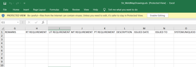
3.4.7 Import Multiple Weld Map Drawings
If you want to import multiple weld map drawings together, do the following,
- Click
 (TEMPLATE button) on the Weld Map Drawings page. See Fig 3.4.
A template will be downloaded as an excel worksheet to enter the details of weld map drawings.
-
Enter the relevant details in the required columns on the excel worksheet.
-
Once you have added the weld map drawing details in the excel worksheet, save the excel worksheet on your computer.
- Click
 (IMPORT button). See Fig 3.4.
A new window opens for importing the excel worksheet saved on your computer.

- Click
 (Browse button) to select the excel worksheet to be uploaded.
 - Select the excel worksheet you want to upload from your computer.
-
Click
 (Upload button) to export the weld map drawings that are included in the excel worksheet.


The details of the weld map drawings in the worksheet will be displayed in the Weld Map Drawings page.
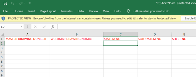
3.5 Sheet Number
The Sheet No tab in the Project Data menu helps you to add the sheet number for a weld map drawing. The sheet number is nothing but a page number of the weld map drawing.
|
If the weld map drawing is provided in single sheet, the Sheet No should be 1 of 1. If the drawing is stretched to two pages, then the Sheet No should be 1 of 2 and 2 of 2. |
If you want to add the sheet number, do the following,
- Click Sheet No in the Project Data menu.
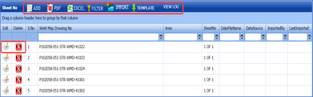
The Sheet No page opens.

Figure 3.5 Sheet No page
3.5.1 Add a Sheet Number
If you want to add a sheet number, do the following,
- Click
 (ADD button) in the Sheet No page. See Fig 3.5.
A new window opens to add the sheet number for a weld map drawing.
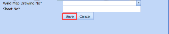
 Note: The fields notified with a symbol (*) are mandatory. You must enter the relevant details in that fields before saving.
 -
In the Weld Map Drawing No box, select the weld map drawing number from a drop-down list.
 Note: If you want to add the sheet number for any new weld map drawings. You must add the respective weld map drawing details by using the Weld Map Drawings tab.
 - In the Sheet No box, enter the sheet number of the weld map drawing.
-
Click Save.


The sheet number for the corresponding weld map drawing is successfully added.
3.5.2 Edit Any Sheet Number
If you want to edit any existing sheet number for the weld map drawing number in the Sheet No page, do the following,
- Click
 (Edit icon) in the Edit column for the respective weld map drawing number. See Fig 3.5.
A new window opens to edit the sheet number for the weld map drawing number.
-
Click a box where you want to edit the details, and then edit the details in the respective box.
-
Click Save.

3.5.3 Delete Any Sheet Number
If you want to delete any specific sheet number of the weld map drawing number from the list of sheet numbers, you can use  (Delete icon) provided in the Delete column of the Sheet No page, See Fig 6.5. To know how to delete, see the topic, “Delete Any Area”.
3.5.4 Export Sheet Number List
You can export a list of sheet numbers of the weld map drawing numbers added in the Sheet No page in the pdf and excel formats. To know how to export, see the topic, “Export Areas list” in the Area option.
3.5.5 Filter Any Sheet Number
If you want to filter any sheet number from the list of sheet numbers in the Sheet No page, you can use the (FILTER button). To know how to filter, see the topic ,”Filter Any Area”.
3.5.6 Import Multiple Sheet Numbers
If you want to import multiple sheet numbers together, do the following,
- Click
 (TEMPLATE button) on the Sheet No page. See Fig 3.5.
A template will be downloaded as an excel worksheet to enter the details of weld map drawing numbers including their sheet numbers.
-
Enter the relevant details in the required columns on the excel worksheet.
- Once you have added the sheet number details in the excel worksheet, save the excel worksheet on your computer.
-
Click
 (IMPORT button). See Fig 3.5.
A new window opens for importing the excel worksheet saved on your computer.

-
Click
 (Browse button) to select the excel worksheet to be uploaded.
 -
Select the excel worksheet you want to upload from your computer.
- Click
 (Upload button) to export the sheet numbers that are included in the excel worksheet.


The details of the sheet numbers in the worksheet will be displayed in the Sheet No page.
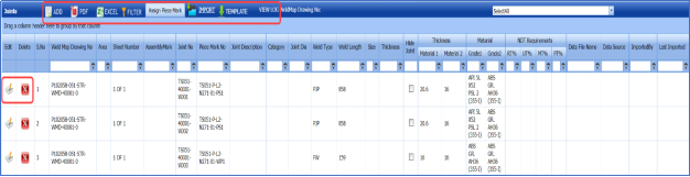
3.6 Joints
In structural project, joints are the points where two or more pieces of materials for example pipes, are joined by welding. The Joints tab in the Project Data helps you add the joint details including joint number, welding type, and piece mark number.
If you want to add any joint details, do the following,
- Click Joints in the Project Data menu.
The Joints page opens.
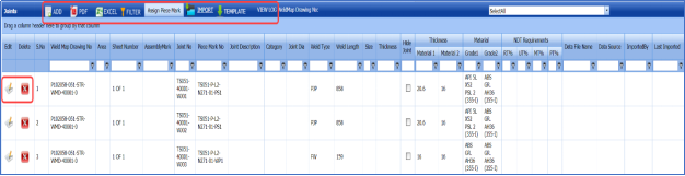
Figure 3.6 Joints page
3.6.1 Add a Joint
If you want to add a joint, do the following,
- Click
 (ADD button) in the Joints page. See Fig 3.6.
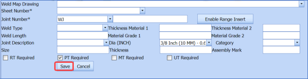
A new window opens to add a joint.

 Note: The fields notified with a symbol (*) are mandatory. You must enter the relevant details in that fields before saving.
 - In the Weld Map Drawing No box, enter the weld map drawing number.
-
In the Sheet Number box, select a sheet number from a drop-down list.
-
In the Joint Number box, select the joint number from a drop-down list.
 Note: If you want to enter the range for the joint number, click
  and then enter the ranges in the From and To boxes, respectively.
 - In the Weld Type box, select a weld type from a drop-down list.
-
In the Thickness Material 1 box, enter the thickness of the first material.
-
In the Thickness Material 2 box, enter the thickness of the second material.
-
In the Weld Length box, enter the length of welding.
-
In the Dia (INCH) box, enter the diameter of the joint.
-
In the Size box, enter the size of the welding.
-
In the Thickness box, enter the thickness of the welding.
-
In the Category box, select the category from a drop-down list.
-
In the Assembly Mark box, enter the assembly mark details.
-
Select the NDT requirement from the following options such as RT Required, PT Required, MT Required, and UT Required.
-
Click Save.


The joint is successfully added.
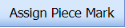
3.6.2 Assign Piece Mark Number
If you want to assign the piece mark number for any joint number.
- Click
 (Assign Piece Mark button) in the Joints page.
The Joint Piece Mark window opens.

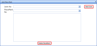
-
In the Joint No box, select the joint number from a drop-down list.
Once you have selected the joint number, the piece mark numbers related with the selected joint number appear.

- If you want to assign a new piece mark number for the selected joint number, in the Piece Mark No box, click and then select the piece mark number from a drop-down list.
A new piece mark number will be listed along with the existing piece mark numbers.

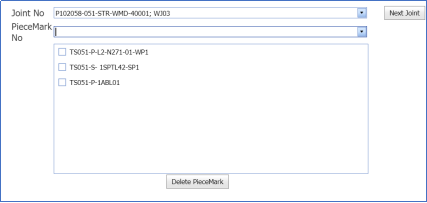
-
Select the new piece mark number.
Once you have selected the new piece mark number, the selected piece mark number is assigned to the respective joint number.
 Note: If you want to delete any piece mark number, select the respective piece mark and click (Delete Piece Mark button). Once you have deleted the piece mark number, the joints related with this piece mark number will also be deleted.

3.6.3 Edit Any Joint
If you want to edit any existing joint in the Joints page, do the following,
- Click
 (Edit icon) in the Edit column for the respective joint. See Fig 3.6.
A new window opens to edit the joint.
- Click any box where you want to edit the details, and then edit the details in the respective box.
-
Click Save.

3.6.4 Delete Any Joint
If you want to delete any specific joint from the list of joints, you can use  (Delete icon) provided in the Delete column of the Joins page, See Fig 6.6. To know how to delete, see the topic, “Delete Any Area”.
3.6.5 Export Joints List
You can export a list of joints added in the Joints page in the pdf and excel formats. To know how to export, see the topic, “Export Areas list” in the Area option.
3.6.6 Filter Any Joint
If you want to filter any joint from the list of joints in the Joints page, you can use the (FILTER button). To know how to filter, see the topic, ”Filter Any Area”.
3.6.7 Import Multiple Joints
You can import multiple joint details together by using a pre-defined excel template given in the application. If you want to import multiple joints together, do the following,
- Click
 (TEMPLATE button) on the Joints page. See Fig 3.6.
A template will be downloaded as an excel worksheet to enter the details of joints.
-
Enter the relevant details in the required columns on the excel worksheet.
-
Once you have added the joint details in the excel worksheet, save the excel worksheet on your computer.
-
Click
 (IMPORT button). See Fig 3.6.
A new window opens for importing the excel worksheet saved on your computer.

-
Click
 (Browse button) to select the excel worksheet to be uploaded.
 -
Select the excel worksheet you want to upload from your computer.
-
Click
 (Upload button) to export the joints that are included in the excel worksheet.


The details of the joints included in the worksheet will be displayed in the Joints page.
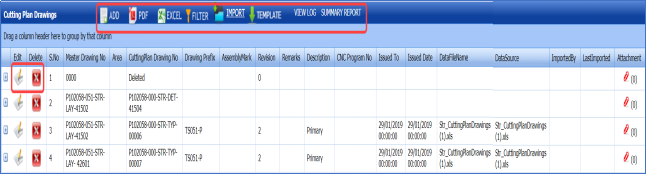
3.7 Cutting Plan Drawings
Cutting plan drawing is provided for each master drawing. Usually the Cutting Plan Drawing is prepared in AutoCAD. The drawing portion of the cutting plan drawing will be screen captured. A cutting plan drawing report is generated for sending to the clients.
If you want to add any cutting plan drawing details, do the following,
- Click Cutting Plan Drawings in the Project Data menu.
The Cutting Plan Drawings page opens.
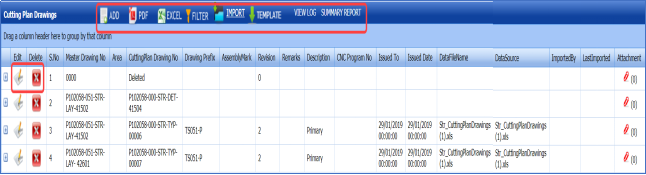
Figure 3.7 Cutting Plan Drawings page
3.7.1 Add a Cutting Plan Drawing
If you want to add a cutting plan drawing, do the following,
- Click
 (ADD button) in the Cutting Plan Drawings page. See Fig 3.7.
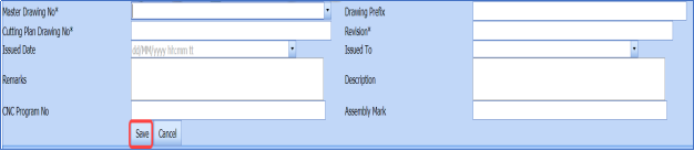
A new window opens to add a cutting plan drawing.

 Note: The fields notified with a symbol (*) are mandatory. You must enter the relevant details in that fields before saving.
 -
In the Master Drawing No box, select a master drawing number from a drop-down list.
-
In the Drawing Prefix box, enter the drawing prefix.
-
In the Cutting Plan Drawing No box, enter a cutting plan drawing number.
-
In the Revision box, enter the revision number.
-
In the Remarks box, enter your remarks if any.
-
In the Issued Date box, choose the issued date of the cutting plan drawing.
-
In the Issued To box, select the purpose of issuing the cutting plan drawing, from a drop-down list.
-
In the Description box, enter the description for the added cutting plan drawing.
-
In the (Computer Numerical Control) CNC Program No box, enter the CNC program number.
-
In the Assembly Mark box, enter the assembly mark.
-
Click Save.


The cutting plan drawing is successfully added.
3.7.2 Attach a File into a Cutting Plan Drawing
If you want to attach any file with any cutting plan drawing listed in the Cutting Plan Drawings page, follow the procedures given in the topic “Attach a file into a client master drawing” in the Client Master Drawing section.
3.7.3 Edit Any Cutting Plan Drawing
If you want to edit any existing cutting plan drawing in the Cutting Plan Drawings page, do the following,
- Click
 (Edit icon) in the Edit column for the respective cutting plan drawing. See Fig 3.7.
A new window opens to edit the cutting plan drawing.
-
Click any box where you want to edit the details, and then edit the details in the respective box.
-
Click Save.

3.7.4 Delete Any Cutting Plan Drawing
If you want to delete any specific cutting plan drawing from the list of cutting plan drawings, you can use  (Delete icon) provided in the Delete column of the Cutting Plan Drawings page, See Fig 6.7. To know how to delete, see the topic, “Delete Any Area”.
3.7.5 Export Cutting Plan Drawings List
You can export a list of cutting plan drawings added in the Cutting Plan Drawings page in the pdf and excel formats. To know how to export, see the topic, “Export Areas list” in the Area option.
3.7.6 Filter Any Cutting Plan Drawing
If you want to filter any cutting plan drawing from the list of cutting plan drawings in the Cutting Plan Drawings page, you can use the (FILTER button). To know how to filter, see the topic, ”Filter Any Area”.
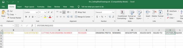
3.7.7 Import Multiple Cutting Plan Drawings
If you want to import multiple cutting plan drawings together, do the following,
- Click
 (TEMPLATE button) on the Cutting Plan Drawings See Fig 3.7.
A template will be downloaded as an excel worksheet to enter the details of cutting plan drawings.

- Enter the relevant details in the required columns on the excel worksheet.
-
Once you have added the weld map drawing details in the excel worksheet, save the excel worksheet on your computer.
-
Click
 (IMPORT button). See Fig 3.7.
A new window opens for importing the excel worksheet saved on your computer.

-
Click
 (Browse button) to select the excel worksheet to be uploaded.
 -
Select the excel worksheet you want to upload from your computer.
-
Click
 (Upload button) to export the cutting plan drawings that are included in the excel worksheet.


The details of the cutting plan drawings in the worksheet will be displayed in the Cutting Plan Drawings page.
3.8 Piece Mark number
The materials used in the Structural Project are cut into multiple pieces by using the cutting plan drawings, where each piece is provided with respective unique number also known as piece mark number. The piece mark number is manually added by a user, and mapped later with weld joints.
The Piece Mark Number tab in the Project Data helps you add the piece mark number details including cutting plan drawing number. If you want to add any piece mark number details, do the following,
- Click Piece Mark Number in the Project Data menu.
The Piece Mark Number page opens.
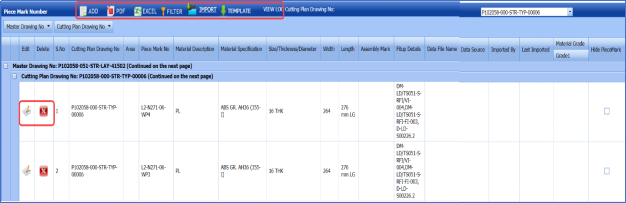
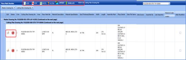
Figure 3.8 Piece Mark Number page
The Master Drawing No box and Cutting Plan Drawing No boxes provided in the upper right-side of the Piece Mark Number page including a drop-down arrow to easily sort the specific master drawing number and cutting plan drawing number. See Fig 3.8.
3.8.1 Add a Piece Mark Number
If you want to add a piece mark number, do the following,
- Click
 (ADD button) in the Piece Mark Number page. See Fig 3.8.
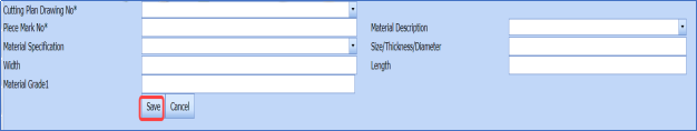
A new window opens to add a piece mark number.

 Note: The fields notified with a symbol (*) are mandatory. You must enter the relevant details in that fields before saving.
 - In the Cutting Plan Drawing No box, select a cutting plan drawing number from a drop-down list.
-
In the Piece Mark No box, enter a piece mark number from a drop-down list.
-
In the Material Description box, select the material description from a drop-down list.
-
In the Material Specification box, select the material specification from a drop-down list.
-
In the Size/Thickness/Diameter box, enter the size/thickness/diameter of the material.
-
In the Width box, enter the width of the material.
-
In the Length box, enter the length of welding.
-
In the Material Grade 1 box, enter the grade 1 material details.
-
Click Save.


The piece mark number is successfully added.
3.8.2 Edit Any Piece Mark Number
If you want to edit any existing piece mark number in the Piece Mark Number page, do the following,
- Click
 (Edit icon) in the Edit column for the respective piece mark number. See Fig 3.8.
A new window opens to edit the piece mark number.
- Click any box where you want to edit the details, and then edit the details in the respective box.
-
Click Save.

3.8.3 Delete Any Piece Mark Number
If you want to delete any specific piece mark number from the list of piece mark numbers, you can use  (Delete icon) provided in the Delete column of the Piece Mark Number page, See Fig 6.8. To know how to delete, see the topic, “Delete Any Area”.
3.8.4 Export Piece Mark Numbers List
You can export a list of piece mark numbers added in the Piece Mark Number page in the pdf and excel formats. To know how to export, see the topic, “Export Areas list” in the Area option.
3.8.5 Filter Any Piece Mark Number
If you want to filter any piece mark number from the list of piece mark numbers in the Piece Mark Number page, you can use the (FILTER button). To know how to filter, see the topic, ”Filter Any Area”.
3.8.6 Import Multiple Piece Mark Numbers
You can import multiple piece mark numbers together by using a pre-defined template given in the application. If you want to import multiple piece mark numbers together, do the following,
- Click
 (TEMPLATE button) on the Piece Mark Number See Fig 3.8.
A template will be downloaded as an excel worksheet to enter the details of piece mark numbers.
-
Enter the relevant details in the required columns on the excel worksheet.
- Once you have added the piece mark number details in the excel worksheet, save the excel worksheet on your computer.
-
Click
 (IMPORT button). See Fig 3.8.
A new window opens for importing the excel worksheet saved on your computer.

- Click
 (Browse button) to select the excel worksheet to be uploaded.
 -
Select the excel worksheet you want to upload from your computer.
-
Click
 (Upload button) to export the piece mark numbers that are included in the excel worksheet.


The details of the piece mark numbers included in the worksheet will be displayed in the Piece Mark Number page.
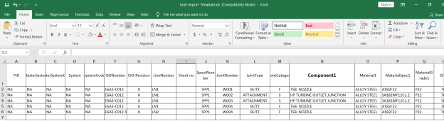
3.9 Import Joints
The Import Joints tab helps you to upload various data for different fields included in the Project Data menu instead of uploading data for each field individually. If you want to import data for different fields, do the following,
- Click the Import Joints tab in the Project Data menu.
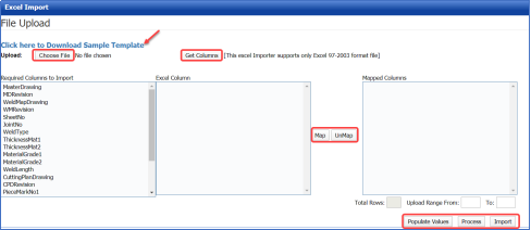
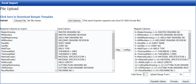
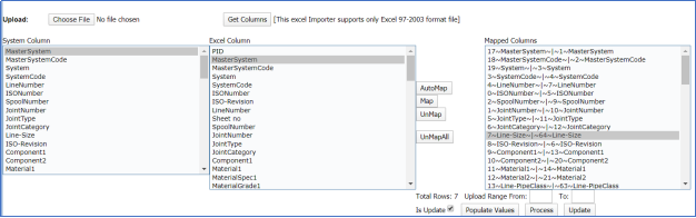
The Excel Import page opens.
-
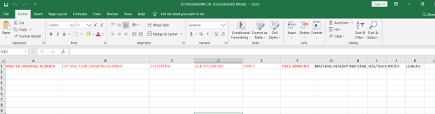
Download a template by clicking “Click here to Download Sample Template” to enter the details of data.
An excel worksheet will be downloaded.
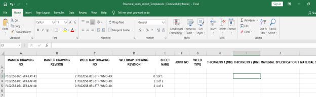
-
Enter the relevant details in the respective column of the excel worksheet based on the columns listed in the Required Columns to Import field.
-
Click
 (Choose File button).
Once the file has been uploaded successfully, you receive a message, “Successfully uploaded”
-
Click
 (Get Columns button).
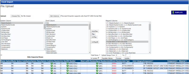
The columns added in the excel worksheet will be listed in the Excel Column field. The system automatically maps the Required Columns to Import field and the Excel Column field and displays in the Mapped Columns field.

-
If you want to map any columns or to u map any mapped columns, select the respective columns and then click
 (Map button) and
  (UnMap button) accordingly.
 -
Once you have completed the mapping and un mapping of columns, in the Upload Range From and To fields, enter the range of rows you want to upload from the excel worksheet.
 Note: In the Total Rows field, the system indicates the total number of rows filled in the excel worksheet.
 Tip: You must enter the upload starting range as two in the Upload Range From field because a first row in the excel worksheet is having heading of the columns.
 -
Click
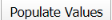 (Populate Value button).
 -
Click
 (Process button).
Once you have clicked the Process button, the system processes the columns and displays in the Excel Import page.

-
Click (Import button) to import the data added in the excel worksheet.


3.10 Joints Bulk Edit
The Joints Bulk Edit tab in the Structural menu used to hide the specific joints, which are added using the Joints tab.
|
Once the joints have been hidden, the joints will not be available while adding any fit-up request. |
If you want to hide any joints, do the following,
- Click the Joints Bulk Edit tab.
The Joints Bulk Update page opens with a list of added joints.
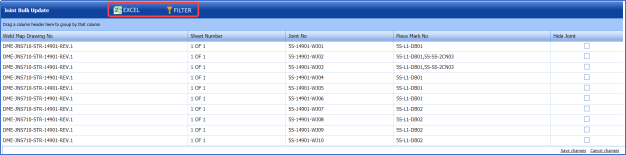
The Joints Bulk Update page shows the weld map drawing number, sheet number, and piece mark number for the corresponding joint number.
- If you want to hide any joints, select the checkbox of the respective joints, in the Hide Joint column of the Joints Bulk Update page.
-
Click Save Changes.
The selected joints will be hidden.
3.11 Assign Unique/ WPS No
The Assign Unique/WPS No tab in the Project Data menu allows you to assign the unique and WPS numbers for the specific joint number, piece mark number, and weld map drawing number.
3.11.1 Assign Unique No
If you want to assign a unique number for any joint number, piece mark number, and weld map drawing number, do the following,
- Click the Assign Unique/WPS No tab in the Project Data menu.
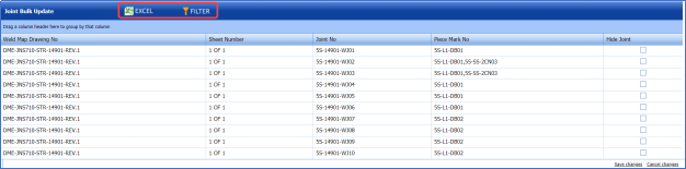
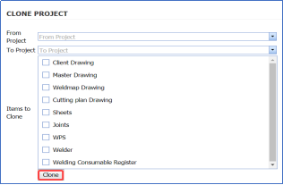
The Assign Unique/WPS No page opens including a list of joint numbers, piece mark numbers, and weld map drawing numbers.

-
Click the Assign Unique No option.
A list of unique numbers appears below the Assign Unique No option.
- If you want to assign any unique number, select the respective unique number, and then select the respective check boxes of the joint numbers, piece mark numbers, and weld map drawing numbers provided in the Assign?
-
Click Save.

3.11.2 Assign WPS No
If you want to assign a WPS number for any joint number, piece mark number, and weld map drawing number, do the following,
- Click the Assign WPS No option in the Assign Unique No/WPS No page.
A list of unique numbers appears below the Assign WPS No option.
-
If you want to assign any WPS number, select the respective WPS number, and then select the respective check boxes of the joint numbers, piece mark numbers, and weld map drawing numbers provided in the Assign? column.
-
Click Save.

3.12 Clone Project
The Clone Project tab in the Project Data menu helps you to clone the items of any one project to another project. Once you have completed the project cloning, the items are copied into the selected project without need to uploading the items again. If you want to clone any project, do the following,
-
Click the Clone Project tab in the Project Data menu.
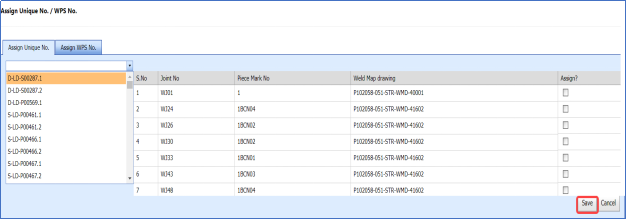
The CLONE PROJECT page opens.

Figure 3.12: Clone Project page
- In the From Project box, select a project from which you want to clone the items, from a drop-down list.
-
In the To Project box, select a project to which you want to clone the items, from a drop-down list.
- In the Items to clone box, select the items you want to clone.
-
Click Clone.
3.13 Welders in Projects
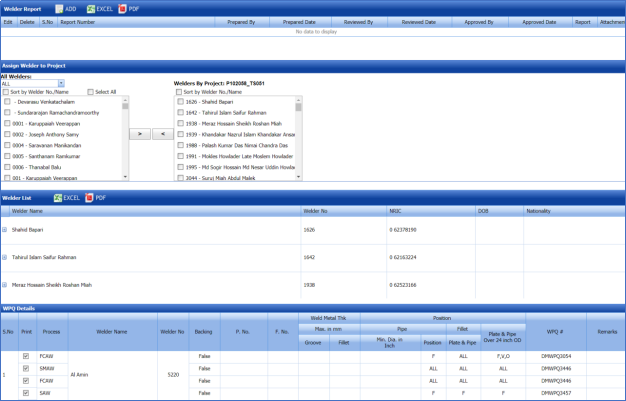
The Welders in Projects tab in the Project Data menu helps you to assign welders for a project. You can add a welder report by using this tab. This tab also helps you to view a welder list and WPQ details.
- Click the Welders in Projects tab in the Project Data menu.
The welders in projects page opens with four fields such as Welder Report, Assign Welder to Project, Welder List, and WPQ Details.

Figure 3.13: Welders in project page
3.13.1 Add a Welder Report
If you want to add a welder report, do the following,
- Click
 (ADD button) in the Welder Report See Fig 3.13.
A new window opens to add a welder report.
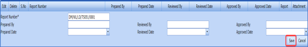
 Tip: A report number for a new welder report will be updated automatically in the Report Number box.
 -
In the Prepared By box, enter the name of welder who has prepared the welder report.
-
In the Received By box, enter the name of welder who has received the welder report.
-
In the Approved By box, enter the name of welder who has approved the welder report.
-
In the Prepared Date box, choose the prepared date of the welder report.
-
In the Received Date box, choose the received date of the welder report.
-
In the Approved Date box, choose the approved date of the welder report.
-
Click Save.


The welder report is successfully added.
3.13.2 Export Welder Reports List
You can export a list of welder reports in the pdf and excel formats. To know how to export, see the topic, “Export Areas list” in the Area option.
3.13.3 Assign Welder to Project
The Assign Welder to Project field in the welders in projects page allows you to assign any welder to the project. If you want to assign any welder to the project, do the following,
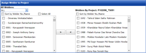
- In the All Welders box, if you want to view all the welders, click ALL otherwise select the respective company’s welder group from a drop-down list to view their welders list.
Once you have selected the company’s welder group, the left-side box shows a list of welders. The right-side box shows a list of welders who has been already assigned for the project.
-
If you want to assign any welder for the project, select the respective welder in the left-side box, and then click (Assign welder button).
The selected welder will be assigned to the project.
- If you want to reject any welder who has been assigned for the project, select the respective welder in the right-side box, and then click (Reject welder button).
3.13.4 Welder List
The Welder List field in the welders in projects page shows the welder details such as welder name, welder number, NRIC, date of birth, and nationality. This field also helps you to assign the WPQs of welders to the project, and remove any WPQs from the project.
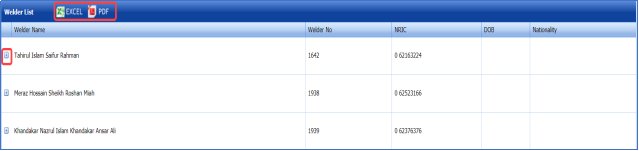
If you click  (Expand icon) of the respective welder, the All WPQ box shows the details of all WPQs of the welder, and the Assigned to Project box shows any WPQ that has been assigned to a project.
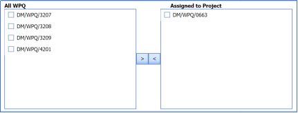
- If you want to assign any WPQ for the project, select the respective WPQ in the All WPQ box, and then click
 (Assign WPQ button).
The selected welder will be assigned to the project.
- If you want to reject any WPQ that has been assigned for the project, select the respective WPQ in the Assigned to Project box, and then click (Reject WPQ button).

3.13.5 WPQ details
The WPQ details field in the welders in projects page shows the WPQ details of each welder including welder’s name, welder number, welding process name, weld metal thickness, and position.
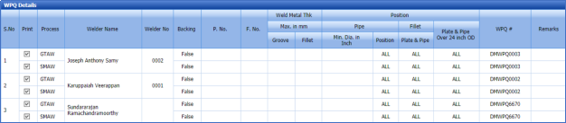
If you want to take a print of any WPQ details, click the checkbox provided in the Print Column.
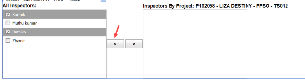
3.14 Inspectors in Projects
The Inspectors in Projects tab in the Project Data menu helps you to map inspectors for the specific project.
- Click the Inspectors in Projects tab.
The Project Mapping – Inspectors page opens.
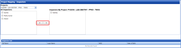
Figure 3.14: Project Mapping – Inspectors page
The Project Mapping – Inspectors page shows a list of inspectors, which is added in the Master Data. If you want to map any inspectors for a specific project, do the following,
-
Select a project you want from the Projects box.
A list of available inspectors will be displayed.
-
Select the check box of the respective inspector which you want to map for the selected project.

-
Click
 (Map icon).
The selected inspectors are mapped for the selected project.
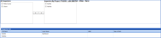
The Inspector List window shows the inspector’s name, login name, NRIC, and Date of birth.


3.15 WPS by Projects
WPS is a written instruction that specifies materials, consumables and edge preparations for a given joint. The WPS lists the pre- and post-weld operations including heat treatments; machining, grinding, and dressing of the weld.
The WPS by Projects tab in the Project Data menu helps you to add a WPS report and assign the WPS to a project.
- Click the WPS by Projects tab in the Project Data menu.
The WPS by projects page opens with two fields such as WPS Summary and Assign WPS to Project.
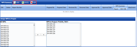
Figure 3.15: WPS by projects page

3.15.1 Add a WPS Report
If you want to add a new WPS report, do the following,
- Click
 (ADD button) in the WPS Summary field. See Fig 3.15.
A new window opens to add a WPS report.

 Tip: A report number for a new WPS report will be updated automatically in the Report Number box.
 - In the Prepared By box, enter the name of a person who has prepared the WPS report.
-
In the Reviewed By box, enter the name of a person who has reviewed the WPS report.
-
In the Approved By box, enter the name of a person who has approved the WPS report.
-
In the Prepared Date box, choose the prepared date of the WPS report.
-
In the Reviewed Date box, choose the reviewed date of the WPS report.
-
In the Approved Date box, choose the approved date of the WPS report.
-
Click Save.

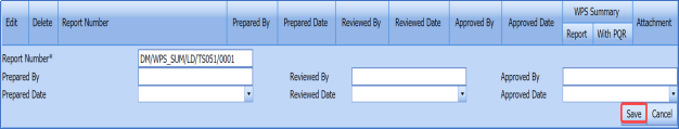

The WPS report is successfully added.
3.15.2 Export WPS Reports List
You can export a list of added WPS reports in the pdf and excel formats. To know how to export, see the topic, “Export Areas list” in the Area option.
3.15.3 Assign WPS to Project
The Assign WPS to Project field in the WPS in projects page allows you to assign the WPS to the project. If you want to assign any WPS to the project, do the following,
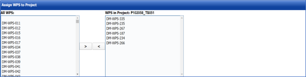
In the Assign WPS to Project field, the All WPS box displays a list of available WPS. The WPS in Project box displays a list of WPS that has been already assigned for the project.
- If you want to assign any WPS for the project, select the respective WPS in the ALL WPS box, and then click
 (Assign welder button).
The selected WPS will be assigned to the project.
- If you want to reject any WPS that has been assigned for the project, select the respective WPS in the WPS in Project box, and then click
 (Reject welder button).


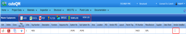
3.16 Master Equipment
The Master Equipment tab in the Project Data menu used to add a master equipment.
- Click Master Equipment in the Project Data menu.
The Master Equipment page opens.

Figure 3.16: Master Equipment
3.16.1 Add a Master Equipment
If you want to add a master equipment,
- Click (ADD button) in the Master Equipment page. See Fig 3.16.
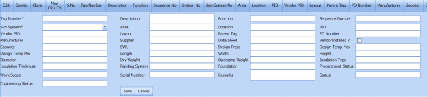
A new window opens to add a master equipment.

- In the Tag Number box, enter the tag number.
-
In the Description box, enter the description for the master equipment.
-
In the Sequence Number box, enter the sequence number.
-
In the Sub System box, select a sub system.
-
In the Area box, enter the area name.
-
In the Location box, enter the location name.
-
In the Vendor PID box, enter the vendor PID number.
-
In the Layout box, enter the layout detail.
-
In the Parent Tag box, enter the parent tag number.
-
In the PO Number box, enter the PO number.
-
In the Manufacturer box, enter the manufacturer name.
-
In the Supplier box, enter the supplier name.
-
In the Length box, enter the length of the master equipment.
-
In the Width box, enter the width of the master equipment.
-
In the Height box, enter the height of the master equipment.
-
In the Diameter box, enter the diameter of the master equipment.
-
In the Dry Weight box, enter the dry weight of the master equipment.
-
In the Operating Weight box, enter the operating weight of the master equipment.
-
In the Insulation Type box, enter the insulation type.
-
In the Serial Number box, enter the serial number.
-
In the Remarks box, enter your remarks if any.
-
In the Engineering Status box, enter the engineering status.
-
Click Save.
The master equipment is successfully added.
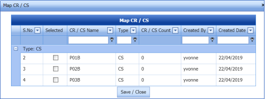
3.16.2 Map CR/CS
If you want to map Check Record/Check Sheet (CR/CS) for any added master equipment,
- Click
 (Add icon) provided in the Map CR/CS column.
The Map CR/CS window opens.
-
Select the checkbox of the CR/CS which you want to map.
-
Click Save/Close.


3.16.3 Clone a Master Equipment
The Clone option in the Clone column of the Master Equipment page used to add a master equipment as a copy of the previously added master equipment, See Fig 3.16.
- Click
 (Clone icon) in the Clone column of the Master Equipment page.
A new window opens to add the master equipment.
-
Enter the details of the master equipment.
The new master equipment will be added.

3.16.4 Edit Any Master Equipment
If you want to edit any master equipment in the Master Equipment page, do the following,
- Click
 (Edit icon) in the Edit column for the respective master equipment. See Fig 3.16.
The page shows the added details of the master equipment.
-
Click any box where you want to edit the details, and then edit the details in the respective box.
-
Click Save.

3.16.5 Export Master Equipments List
You can export a list of master equipment added in the Master Equipment page in the pdf and excel formats. To know how to export, see the topic, “Export Areas list” in the Area option.
3.16.6 Filter Any Master Equipment
If you want to filter any master equipment from the list of master equipments in the Master Equipment page, you can use the  (FILTER button). To know how to filter, see the topic, ”Filter Any Area”.
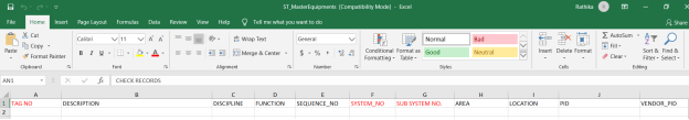
3.16.7 Import Multiple Master Equipments
You can import multiple master equipments together by using a pre-defined template given in the application. If you want to import multiple master equipments together, do the following,
- Click
 (TEMPLATE button) on the Master Equipment See Fig 3.16.
A template will be downloaded as an excel worksheet to enter the details of master equipment.

- Enter the relevant details in the required columns on the excel worksheet.
-
Once you have added the master equipment details in the excel worksheet, save the excel worksheet on your computer.
- Click
 (IMPORT button). See Fig 3.16.
A new window opens for importing the excel worksheet saved on your computer.

- Click
 (Browse button) to select the excel worksheet to be uploaded.
 - Select the excel worksheet you want to upload from your computer.
-
Click
 (Upload button) to export the piece mark numbers that are included in the excel worksheet.


The details of the master equipments included in the worksheet will be displayed in the Master Equipment page.
3.17 Systems
You can add the details of systems to be used in the Structural project by using the Systems tab in the Project Data menu. If you want to navigate to Systems,
- Click Systems in the Project Data menu.
The System page opens.

Figure 3.17: System page
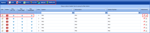
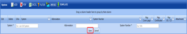
3.17.1 Add System
If you want to add a new system, do the following steps,
- Click
 (ADD button) in the System page. See Fig 3.17.
A new window opens to add a new system.

 Note: The fields notified with a symbol (*) are mandatory. You must enter the relevant details in that fields before saving.
 - In the System box, enter the system name.
-
In the Abbreviation box, enter the abbreviation for the system name.
-
In the System Number box, enter the system number.
-
Click Save.
The system is successfully added and listed in the System page.
 Note: If you want to map cover page for any added system, click the respective
  (Add icon) provided in the Map Cover Page column and add the cover pages.
If you want to map certificates for any added system, click the respective (Add icon) provided in the Map Certificates column and add the cover pages.
If you want to map Check Record/Check Sheet (CR/CS) for any added system, click the respective (Add icon) provided in the Map CR/CS column and add the cover pages.


3.17.2 Edit System
If you want to edit any existing system in the System page,
- Click
 (Edit icon) of the respective System. See Fig 3.17.
The System page shows the details of the selected system.
-
Edit the details where you want.
-
Click Save.

3.17.3 Delete System
If you want to delete any existing system in the System page, you can use  (Delete icon) provided in the System page. To know how to delete, see the topic, “Delete Any Area”.
3.17.4 Export System List
You can export a list of systems added in the System page in both the pdf and excel formats by using (PDF button) and
  (Excel button). To know how to export, see the topic, “Export Areas list” in the Area option.
3.17.5 Filter System
If you want to filter any specific system in the System page, you can use  (FILTER button) located on the System page. To know how to filter, see the topic, ”Filter Any Area”.
3.17.6 Import Multiple Systems
If you want to import multiple systems together, do the following,
- Click
 (TEMPLATE button). See Fig 3.17.
An excel worksheet will be downloaded with a predefined template to enter the details of systems.
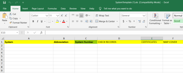
- Enter the required system details in the respective columns of the excel worksheet.
- Once you have added the system details in the excel worksheet, save the excel worksheet on your computer.
-
Click
 (IMPORT button). See Fig 3.17.
A new window opens for importing the excel worksheet saved on your computer.

-
Click
 (Browse button) to select the excel worksheet to be uploaded.
 -
Select the excel worksheet you want to upload from your computer.
-
Click
 (Upload button) to export the systems that are included in the excel worksheet.


The details of the systems in the worksheet will be displayed in the System page.
3.17.7 Attach a File into a System
If you want to attach any file with any system listed in the System page, you can attach the file by using  (Attach icon) in the Attachment column. To know how to attach, follow the procedures given in the topic “Attach a file into a client master drawing”.
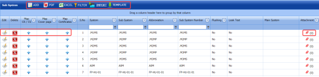
3.18 Sub Systems
The Sub Systems tab in the Project Data menu helps you to add the details of sub systems to be in used in the Structural Project. If you want to navigate to Sub Systems,
- Click Sub Systems in the Project Data menu.
The Sub Systems page opens.

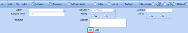
Figure 3.18: Sub System page
3.18.1 Add Sub System
If you want to add a new sub system, do the following steps,
- Click
 (ADD button) in the Sub System page. See Fig 3.18.
A new window opens to add a new sub system.
 Note: The fields notified with a symbol (*) are mandatory. You must enter the relevant details in that fields before saving.
 -
In the System box, select a system from a drop-down list.
-
In the Sub System box, select a sub system from a drop-down list.
-
In the Abbreviation box, enter the abbreviation for the sub system.
-
In the Sub System Number box, enter the sub system number.
- If the added subsystem needs to be flushed, select Yes in the Flushing option otherwise select No.
-
If there is need to perform the leakage test for the added subsystem, select Yes in the Leak Test option otherwise select No.
-
In the Description box, enter the description for the added sub system.
-
Click Save.


The sub system is successfully added and listed in the Sub System page.
3.18.2 Edit Sub System
If you want to edit any existing sub system in the Sub System page,
-
Click
 (Edit icon) of the respective sub system. See Fig 6.18.
The Sub System page shows the details of the selected sub system.
- Edit the details where you want.
-
Click Save.

3.18.3 Delete Sub System
If you want to delete any existing sub system in the Sub System page, you can use  (Delete icon) provided in the Sub System page. To know how to delete, see the topic, “Delete Any Area”.
3.18.4 Export Sub System List
You can export a list of sub systems added in the Sub System page in both the pdf and excel formats by using  (PDF button) and
  (Excel button). To know how to export, see the topic, “Export Areas list” in the Area option.
3.18.5 Filter Sub System
If you want to filter any specific sub system in the Sub System page, you can use (FILTER button) located on the Sub System page. To know how to filter, see the topic, ”Filter Any Area”.
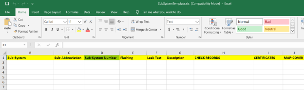
3.18.6 Import Multiple Sub Systems
If you want to import multiple sub systems together, do the following,
- Click
 (TEMPLATE button). See Fig 3.18.
An excel worksheet will be downloaded with a predefined template to enter the details of sub systems.
-
Enter the required sub system details in the respective columns of the excel worksheet.
- Once you have added the sub system details in the excel worksheet, save the excel worksheet on your computer.
- Click
 (IMPORT button). See Fig 3.18.
A new window opens for importing the excel worksheet saved on your computer.

- Click
 (Browse button) to select the excel worksheet to be uploaded.
 - Select the excel worksheet you want to upload from your computer.
-
Click
 (Upload button) to export the sub systems that are included in the excel worksheet.
 The details of the sub systems in the worksheet will be displayed in the Sub System page.


3.18.7 Attach a File into a Sub System
If you want to attach any file with any sub system listed in the Sub System page, you can attach the file by using  (Attach icon) in the Attachment column. To know how to attach, follow the procedures given in the topic “Attach a file into a client master drawing”.
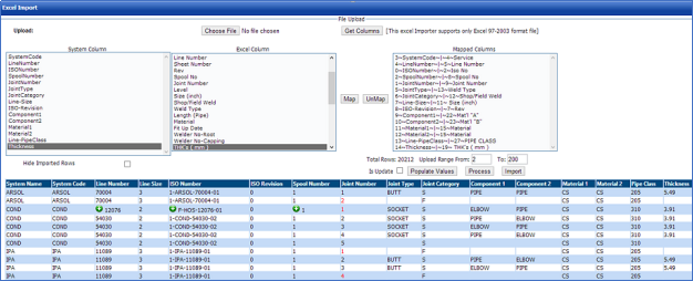
3.19 Import from Excel – Masters
The Import from Excel – Masters tab helps you to upload master data for all fields instead of uploading data for each field individually.
If you want to import master data for different fields, do the following,
- Click Import from Excel – Masters in the Project Data menu.
The File Upload page opens.
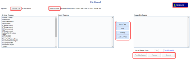
Figure 3.19: File Upload page
- Download a template by using
 (TEMPLATE button) to enter the details of master data.
An excel worksheet will be downloaded with a pre-defined template to the details.

- Enter the relevant details in the respective column of the excel worksheet.
-
Click
 (Choose File button).
Once the file has been uploaded successfully, you receive a message, “Successfully uploaded”
-
Click
 (Get Columns button).
The columns added in the excel worksheet will be listed in the Excel Column field.
 Note: Make sure that the Excel Column field must have all the columns as in the System Column field.
 -
To map the columns in the System Column and Excel Column fields, do one of the following,
-
- If you want to map the columns automatically, click
 (AutoMap button).
The columns will be mapped automatically and displayed in the Mapped Columns field.
- If you want to map each column manually, select the respective columns in both the System Columnand Excel Column fields and then click
 (Map button).
The selected columns will be mapped and displayed in the Mapped Columns field.

- If you want to map the columns automatically, click
-
- To un-map the columns in the Mapped Columns field, select the respective column and then click
 (UnMap button).
Once you have completed the mapping and un-mapping of columns, you must enter the range for uploading the data from the excel worksheet.
 Note: In the Total Rows field, the system indicates the total number of rows filled in the excel worksheet.
 Tip: You must enter the upload starting range as two in the Upload Range From field because a first row in the excel worksheet is having heading of the columns.
 - In the Upload Range From and To fields, enter the range of rows you want to upload from the excel worksheet.
-
Click
 (Populate Values button).
The data are populated.
- Click
 (Process button).
The system processes all the uploaded data and displays in the Excel Import page.

- Click
 (Update button) to import the uploaded data.
The data will be successfully imported.


3.20 Workflow Settings
The Workflow Settings tab in the Project Data menu used to set a workflow in the Structural project.
- Click Workflow Settings in the Project Data menu.
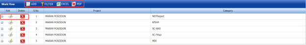
The Workflow page opens.

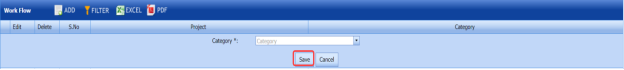
Figure 3.20: Workflow page
3.20.1 Add a Workflow
If you want to add a workflow,
- Click
 (ADD button) in the Workflow page. See Fig 3.20.
The page shows a new window to add the category.

-
In the Category box, select a category from a drop-down list.
-
Click Save.
The added category will be listed in the Workflow page. See Fig 3.20.
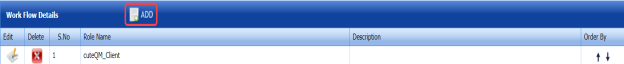
-
Click
 (Add icon) of the respective category.
The Workflow Details window opens.

- Click
 (ADD button) in the Workflow Details window.
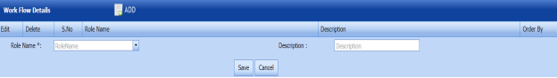

-
In the Role Name box, select a role name from a drop-down list.
-
In the Description box, enter the description for the role name.
-
Click Save.


3.20.2 Edit a Workflow
If you want to edit any existing workflow in the Workflow page,
- Click
 (Edit icon) of the respective workflow. See Fig 3.20.
The Workflow page shows the details of the selected workflow.
-
Edit the details where you want.
-
Click Save.

3.20.3 Delete a Workflow
If you want to delete any existing workflow in the Workflow page, you can use  (Delete icon) provided in the Workflow page. To know how to delete, see the topic, “Delete Any Area”.
3.20.4 Export Workflow List
You can export a list of workflows added in the Workflow page in both the pdf and excel formats by using  (PDF button) and
  (Excel button). To know how to export, see the topic, “Export Areas list” in the Area option.
3.20.5 Filter Any Workflow
If you want to filter any specific workflow, you can use (FILTER button) located on the Workflow page. To know how to filter, see the topic, ”Filter Any Area”.
3.21 Job Code
Job codes are individualized sets of numbers assigned to different jobs in order to identify which class a position belongs to. The Job Code tab in the Project Data menu used to add a job code.
- Click Job Code in the Project Data menu.
The Job Code page opens.

Figure 3.21: Job Code page

3.21.1 Add a Job Code
If you want to add a new job code, do the following steps,
- Click
 (ADD button) in the Job Code page. See Fig 3.21.
A new window opens to add a new job code.
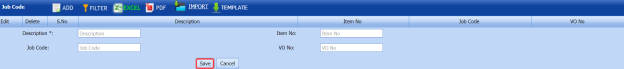
 Note: The fields notified with a symbol (*) are mandatory. You must enter the relevant details in that fields before saving.
 - In the Description box, enter the description for a job code you want to add.
-
In the Item No box, enter the item number.
-
In the Job Code box, enter the job code.
-
In the VO No box, enter the VO number.
-
Click Save.
The job code is added and listed in the Job Code page.


3.21.2 Edit Any Job Code
If you want to edit any existing job code in the Job Code page,
-
Click
 (Edit icon) of the respective job code. See Fig 3.21.
The Job Code page shows the details of the selected job code.
-
Edit the details where you want.
-
Click Save.

3.21.3 Delete Any Job Code
If you want to delete any existing job code in the Job Code page, you can use  (Delete icon) provided in the Job Code page. To know how to delete, see the topic, “Delete Any Area”.
3.21.4 Export Job Code List
You can export a list of job codes added in the Job Code page in both the pdf and excel formats by using  (PDF button) and
  (Excel button). To know how to export, see the topic, “Export Areas list” in the Area option.
3.21.5 Filter Any Job Code
If you want to filter any specific job code in the Job Code page, you can use  (FILTER button) located on the Job Code page. To know how to filter, see the topic, ”Filter Any Area”.
3.21.6 Import Multiple Job Codes
If you want to import multiple job codes together, do the following,
-
Click
 (TEMPLATE button). See Fig 3.21.
An excel worksheet will be downloaded with a predefined template to enter the details of job code.
- Enter the required job code details in the respective columns of the excel worksheet.
- Once you have added the job code details in the excel worksheet, save the excel worksheet on your computer.
- Click
 (IMPORT button). See Fig 3.21.
A new window opens for importing the excel worksheet saved on your computer.

- Click
 (Browse button) to select the excel worksheet to be uploaded.
 - Select the excel worksheet you want to upload from your computer.
- Click
 (Upload button) to export the sub systems that are included in the excel worksheet.


The details of the job codes in the worksheet will be displayed in the Job Code page.
3.22 Inspection Test Plan (ITP)
ITP is a document or series of documents used for quality assurance purposes. ITP outlines how the quality of a particular material will be ensured both at beginning and throughout the service life.
The Inspection Test Plan tab in the Project Data menu allows you to add the inspection test plan report. If you want to add the inspection test plan report, do the following,
- Click the Inspection Test Plan tab in the Project Data menu.
The Inspection Test Plan (ITP) page opens.

Figure 3.22: ITP page
 Note: The fields notified with a symbol (*) are mandatory. You must enter the relevant details in that fields before saving.
 - In the Template box, select a template from a drop-down list appears on the Select from Templates box or the Select from Equipments box.
 Tip: A report number for the ITP report will be updated automatically in the ITP Report Number box.
 - In the ITP Status box, select the ITP status from a drop-down list.
-
In the Date box, choose the date of status update.
- In the Non-Destructive Examination (NDE)box, enter the NDE details.
-
In the Remarks box, enter your remark if any.
-
In the Prepared By box, enter the name of a person who has prepared the ITP report.
-
In the Reviewed By box, enter the name of a person who has reviewed the ITP report.
-
In the Approved By box, enter the name of a person who has approved the ITP report.
-
In the Prepared Date box, choose the prepared date of the ITP report.
-
In the Reviewed Date box, choose the reviewed date of the ITP report.
-
In the Approved Date box, choose the approved date of the ITP report.
-
Click Save.
The ITP report is successfully added.
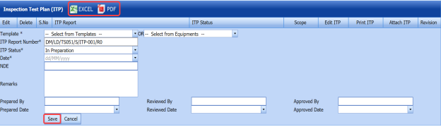


3.22.1 Export ITP reports list
You can export a list of added ITP reports in the pdf and excel formats. To know how to export, see the topic, “Export Areas list” in the Area option.
3.23 Check List
The Check List tab in the Project Data menu helps you to add a check list that will be used in adding a final visual test report.
- Click the Check List tab in the Project Data menu.
The Check List page opens.
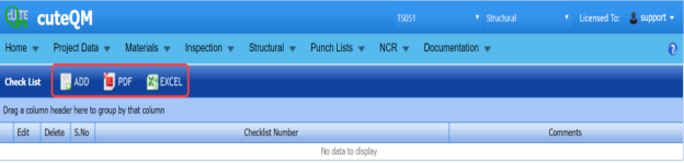
Figure 3.23: Check List page

3.23.1 Add a Check List
If you want to add a check list,
- Click
 (ADD button) in the Check List page. See Fig 3.23.
A new window opens to add a check list.

 Note: The field notified with a symbol (*) is mandatory. You must enter the relevant details in that field before saving.
 - In the Check List box, enter the check list number.
-
In the Comments box, type your comments if any.
-
Click Save.
The check list is added successfully.

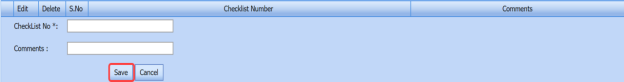

3.23.2 Export Check Lists
You can export a list of added check lists in the pdf and excel formats. To know how to export, see the topic, “Export Areas list” in the Area option.
3.24 NDT Procedures
The NDT procedures tab in the Project Data menu helps you to add an NDT procedure. If you want to add an NDT procedure, do the following,
- Click NDT Procedures in the Project Data menu.
The NDT Procedure page opens.
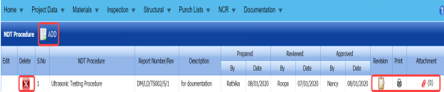
Figure 3.24: NDT Procedure page
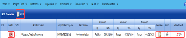
3.24.1 Add an NDT Procedure
If you want to add an NDT procedure,
- Click
 (ADD button) in the NDT Procedure page. See Fig 3.24.
A new window opens to add an NDT procedure.

-
In the NDT Procedure box, select the NDT procedure from a drop-down list.
-
In the NDT Procedure Title box, enter the NDT procedure title.
-
Click Save.

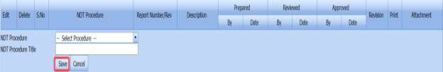
The NDT procedure is successfully added.
3.24.2 Add NDT Procedure Revision
Once you have added the NDT procedure, you must add the NDT procedure revision. You can add multiple revisions for one NDT procedure.
- Click
 (Edit icon) in the Revision column of the NDT Procedure See Fig 3.24.
The NDT Procedure Revision window opens.

-
Click
 (ADD button) in the NDT Procedure Revision window.
A new window opens to add the NDT revision procedure.

 Note: The fields notified with a symbol (*) are mandatory. You must enter the relevant details in that fields before saving.
 Tip: A report number for the revision will be updated automatically in the Report Number/ Revision box.
 - In the Description box, enter the description for the NDT procedure revision.
-
In the Prepared By box, enter the name a person who has prepared the revision.
-
In the Prepared Date box, enter the prepared date of the revision.
-
In the Reviewed By box, enter the name a person who has reviewed the revision.
-
In the Reviewed Date box, enter the reviewed date of the revision.
-
In the Approved By box, enter the name a person who has approved the revision.
-
In the Approved Date box, enter the approved date of the revision.
-
Click Save.

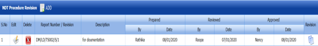

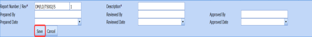


3.24.3 Print an NDT procedure report
If you want to print an NDT procedure report, click (print icon) provided in the Print column of the NDT Procedure page. See Fig 3.24.
3.24.4 Attach a File into an NDT Procedure
If you want to attach any file with the NDT procedure listed in the NDT Procedure page, follow the procedures given in the topic “Attach a file into a client master drawing” in the Client Master Drawing section.
No Comments