
Planning
2.0 Planning
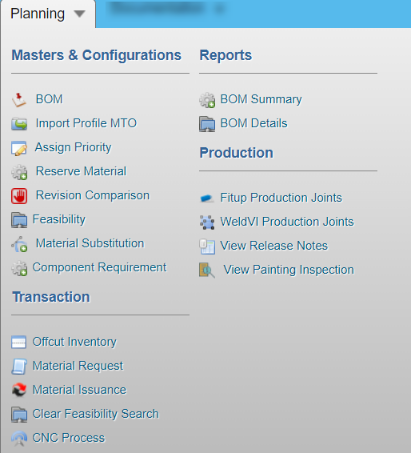
Here, you can manage the material reservation, material substitution, offcut inventory, material requisition, and material issuance. For production purpose, you can add and manage fit up, weld visual, and painting inspection requests.
Once you click the Planning menu, the following tabs open,
2.1 Bill of Material (BOM)
The BOM tab in the Planning menu used to add a BOM including quantity of items needed for the pre- fabrication from the overall quantity in the inventory. To add BOM,
1. Click BOM in the Planning
The Bill of Material page opens.
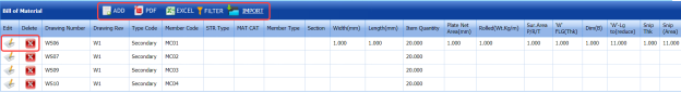
Figure 2.1: Bill of Material page
2.1.1 Add a BOM
If you want to add a BOM,
1. Click  (ADD button) in the Bill of Material See Fig 5.1.
The page opens a new window to add the details of BOM.
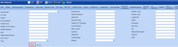
 Note: The field notified with a symbol (*) is mandatory. You must enter the relevant details in that field before saving.
2. In the Drawing No box, select a drawing number from a drop-down list.
3. In the Drawing Rev box, enter the drawing revision number.
4. In the Member Code box, enter the member code.
5. In the Str Type box, enter the structural type.
6. In the Material Category box, enter the material category.
7. In the Member Type box, enter the member type.
8. In the Section box, enter the section name.
9. In the Width MM box, enter the width of the material in mm.
10. In the Length MM box, enter the width of the material in mm.
11. In the Item Quantity box, enter the item quantity.
12. In the Plate Net Area box, enter the plate net area name.
13. In the Rolled box, enter the rolled detail.
14. In the Surface Area box, enter the surface area name.
15. In the Weight FLG Thickness box, enter the weight FLG thickness detail.
16. In the Dimension box, enter the dimension detail.
17. In the Weight LG to Reduce box, enter the weight that needs to be reduced.
18. In the Snip Thickness box, enter the snip thickness value.
19. In the Snip Area box, enter the snip area value.
20. In the Weight Reduced box, enter the reduced weight.
21. In the Mean Length No box, enter the mean length.
22. In the Item box, enter the item name.
23. In the Quantity box, enter the item quantity.
24. In the Material Description box, enter the material description.
25. In the Material Specification box, enter the material specification.
26. In the Item Code box, select an item code.
27. In the Total Quantity box, enter the item’s total quantity.
28. In the UOM box, enter the UOM detail.
29. Click Save.
The BOM including the item quantity is successfully added and listed in the Bill of Material page.
2.1.2 Edit a BOM
If you want to edit any existing BOM in the Bill of Material page, do the following,
1. Click  (Edit icon) in the Edit column for the respective BOM. See Fig 5.1.
The page shows the details of the selected BOM.
2. Click any box where you want to edit the details, and then edit the details in the respective box.
3. Click Save.
2.1.3 Delete a BOM
If you want to delete any existing BOM in the Bill of Material page, you can use  (Delete icon) provided in the Bill of Material page.
2.1.4 Export BOM List
You can export a list of BOMs added in the Bill of Material page in both the pdf and excel formats.
1. If you want to export the BOM list in the pdf format, click  (PDF button).
The BOM list will be downloaded as a pdf file.
2. If you want to export the BOM list in the excel format, click  (Excel button).
The BOM list will be downloaded as an excel file.
2.1.5 Filter a BOM
If you want to filter any BOM from the list of BOMs in the Bill of Material page, do the following,
1. Click  (FILTER button) located on the Bill of Material See Fig 5.1.
Once you clicked the Filter button, the filter box opens in each column of the Bill of Material page.

2. Enter relevant detail in the respective column’s filter box to filter a BOM you want.
2.1.6 Import Multiple BOMs
If you want to import multiple BOM together, do the following,
1. Click  (IMPORT button). See Fig 5.1.
The Excel Import page opens.
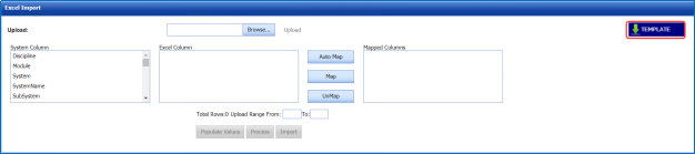
2. Click (TEMPLATE button).
An excel worksheet will be downloaded with a predefined template to enter the details of BOM.
3. Enter the required BOM details in the respective columns of the excel worksheet.
4. Once you have added the BOM details in the excel worksheet, save the excel worksheet on your computer.
5. Click  (Browse button) to select the excel worksheet to be uploaded.
6. Select the excel worksheet you want to upload from your computer.
7. Click  (Upload button) to export the BOM details that are included in the excel worksheet.
The columns added in the excel worksheet will be listed in the Excel Column field.
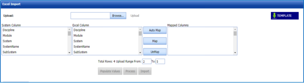
 Note: Make sure that the Excel Column field must have all the columns as in the System Column field.
8. To map the columns in the System Column and Excel Column fields, do one of the following,
a. If you want to map the columns automatically, click  (AutoMap button).
The columns will be mapped automatically and displayed in the Mapped Columns field.
b. If you want to map each column manually, select the respective columns in both the System Column and Excel Column fields and then click  (Map button).
The selected columns will be mapped and displayed in the Mapped Columns field.
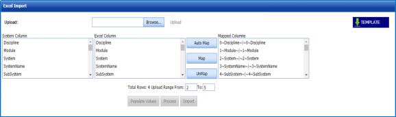
9. To un-map the columns in the Mapped Columns field, select the respective column and then click  (UnMap button).
 Note: In the Total Rows field, the range for uploading the data from the excel worksheet will be updated automatically.
10. Click 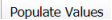 (Populate Values button).
The data are populated.
11. Click  (Process button).
The system processes all the uploaded data and shows if any error with the uploaded data. You can download the error details in the excel worksheet by clicking  (Export to Excel button).
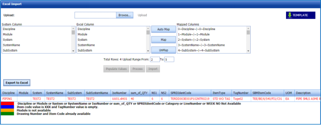
 Note: Different color code explains the different types of errors.
12. Once you have rectified the identified error in the excel worksheet, follow the above procedures to upload the worksheet.
13. Click (Import button) to import the uploaded data.
The data will be successfully imported.
2.2 Import Profile MTO
2.3 Assign Priority
The Assign Priority tab in the Planning menu helps to assign the priority for JDE, Offcut, and FIM warehouses. Likewise, you can assign priority for Module, Level, Type Code, and Cutting Plan Drawing. For example, if you assign the high priority for any warehouse, the materials from the high priority warehouse will be taken initially for performing piping feasibility.
To assign priority,
1. Click Assign Priority in the Planning
The Assign Priority page opens.
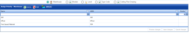
Figure 2.3: Assign Priority page
 Note: You can assign the priority by giving the numbers from 1 to 99.
2. If you want to assign priority for warehouses,
a. Select the Warehouse
The added warehouses will be listed.
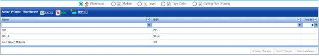
b. In the Priority column, enter the priority numbers for the respective warehouse.
c. Click Save Changes.
3. If you want to assign priority for project modules,
a. Select the Module
The added project modules will be listed.
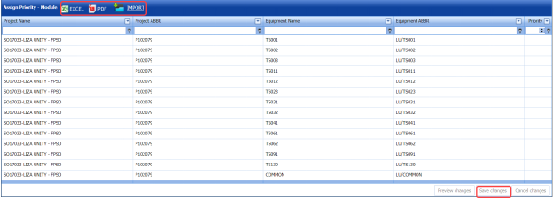
b. In the Priority column, enter the priority numbers for the respective module.
c. Click Save Changes.
4. If you want to assign priority for levels,
a. Select the Level
The added levels will be listed.
Add image
b. In the Priority column, enter the priority numbers for the respective test pack.
c. Click Save Changes.
5. If you want to assign priority for type code,
a. Select the Type Code
The added type code will be listed.
Add image
b. In the Priority column, enter the priority numbers for the respective system.
c. Click Save Changes.
6. If you want to assign priority for cutting plan drawings,
a. Select the Cutting Plan Drawing
The added cutting plan drawings will be listed.
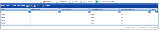
b. In the Priority column, enter the priority numbers for the respective line.
c. Click Save Changes.
2.3.1 Export Assigned Priority List
You can export the assigned priority list in the Assign Priority page in the pdf and excel formats by using  (PDF button) and
  (Excel button). To know how to export, see the topic, “Export BOM List”.
2.4 Reserve Material
The Reserve Material tab in the Planning menu helps to reserve the material from the inventory quantity. To reserve the material,
1. Click Reserve Material in the Planning
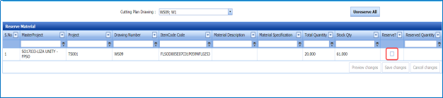
The Reserve Material page opens.
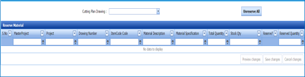
Figure 2.4: Reserve Material page
2.4.1 Reserve a Material
If you want to reserve a material,
1. In the Cutting Plan Drawing box, select a cutting plan drawing number from a drop-down list. See Fig 5.4.
The page shows a list of BOM item codes including the BOM quantity and inventory stock quantity for this corresponding cutting plan drawing number.
 Note: The quantity you want to reserve should be less than the BOM quantity.
2. In the Reserved Qty column, enter the number of items you want to reserve.
3. Once you have entered the reserve quantity, select the respective checkbox in the Reserve?
4. Click Save changes.
The entered material quantity will be reserved.
 Note: If you want to unreserve all the reserved material quantity, click
  (Unreserve All button).
2.5 Revision Comparison
In BOM, when you subsequently revise the quantity of items added against the ISO number, the revision number will be changed. The revision history will be maintained in the back end.
The Revision Comparison tab in the Planning menu helps you to view the revision history of items added in the BOM.
1. Click Revision Comparison in the Planning
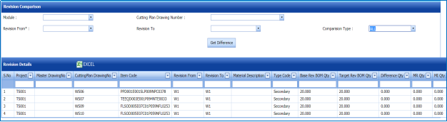
The Revision Comparison page opens.
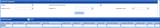
Figure 2.5: Revision Comparison page
2. In the Module box, select a module from a drop-down list.
3. In the Cutting Plan Drawing Number box, select a cutting plan drawing number from a drop-down list.
4. In the Revision From and Revision To boxes, select the revision numbers.
5. In the Comparison Type box, select one of the following,
- If you want to view the revision history for all items, select
- If you want to view the revision history for added items, select
- If you want to view the revision history for removed items, select
- If you want to view the difference in comparison, select Difference Only.
6. Click Get Difference.
The revision history opens based on the given criteria. The revision history shows the total quantity and difference quantity after completing the revision.
2.5.1 Export Revision Comparison Detail
You can export the revision detail generated in the Revision Comparison page in the pdf and excel formats by using  (PDF button) and
  (Excel button). To know how to export, see the topic, “Export BOM List”.
2.6 Feasibility
The Feasibility tab in the Planning menu helps to search the feasibility percentage of items available in the warehouses. Based on the feasibility search percentage, the inspectors will move furtherly for material requisition and material issuance.
1. Click Feasibility in the Planning
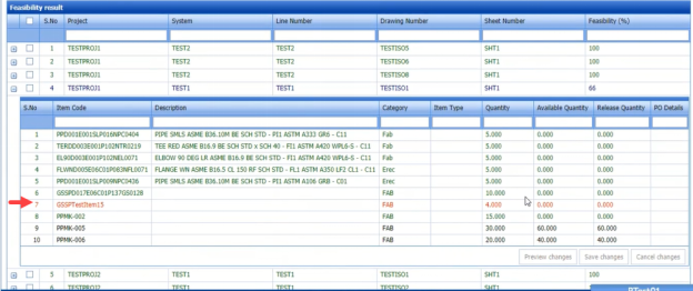
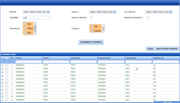
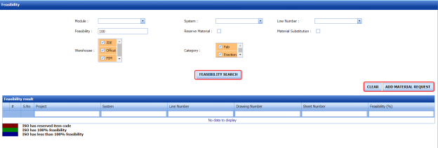 Figure 2.6: Feasibility page
 Note: The feasibility result displayed in different colors explains that status of ISO feasibility.
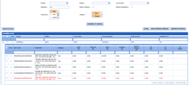
- The feasibility result displayed in Red color shows that the ISO has reserved items.
- The feasibility result displayed in Green color shows that the ISO has 100 percentage feasibility.
- The feasibility result displayed in Blue color shows that the ISO has less than 100 percentage feasibility.
2.6.1 To do Feasibility Search
To search the feasibility percentage, do the following steps in the Feasibility page,
1. In the Module box, select the modules you want.
 Note: According to the selection of modules, the system list will be updated in the System box.
2. In the System box, select the systems you want.
 Note: According to the selection of systems, the line list will be updated in the Line box.
3. In the Line Number box, select the line numbers you want.
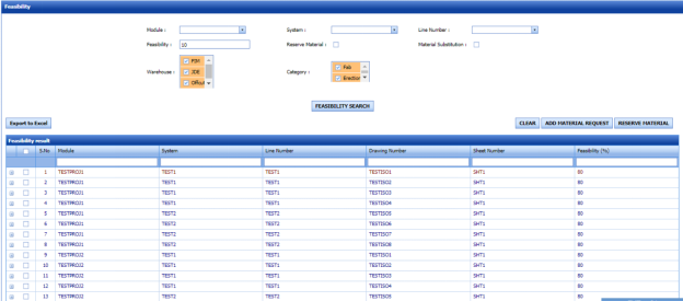
4. In the Feasibility box, enter the feasibility percentage.
 Tip: If you enter 100, the items which have the feasibility percentage of 100 will be listed. If you enter 10, the items which have the feasibility percentage above 10 will be listed.
5. Select the checkbox of Reserve Material option if you want to filter the reserve material items.
The page shows the feasibility of the reserved materials.
6. Select the checkbox of Material Substitution option if you want to filter the material substitution items.
7. If you want to see the feasibility percentage for any particular warehouse, select the warehouse listed in the Warehouse
- If you want to view the feasibility percentage for the items in the JDE warehouse, select the checkbox of JDE.
- If you want to view the feasibility percentage for the items in the Offcut warehouse, select the checkbox of Offcut.
- If you want to view the feasibility percentage for the items in the FIM warehouse, select the checkbox of FIM.
8. In the Category field, select the category whether Fab or Erection.
 Note: If you want clear the given input data, click
  (CLEAR button).
9. Click FEASIBILITYSEARCH.
The feasibility result opens based on the given feasibility percentage.
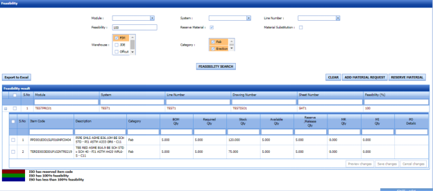
10.  Click (Expand icon) of the respective module.
A new window opens and shows a list of items included in the module.
- BOM Qty – shows the item’s quantity added in the BOM.
- Required Qty – shows the required quantity of item.
- Stock Qty – shows the overall quantity of stock available in all the inventories.
- Available Qty – shows the available quantity of item.
- Reserve/Release Qty – shows the reserve/release quantity of an item.
You can reserve the item here while doing feasibility itself by entering the reserve quantity in the respective field. Make sure that the reserve quantity should not be exceeded the stock quantity.
To reserve the items,
- Select the checkbox of the item for which you want to reserve the quantity.
- Enter the reserve quantity in the Reserve/Release Qty
- Click
 (RESERVE MATERIAL button).
The added quantity will be reserved and updated in the Reserve Material page.
- MR Qty– shows the quantity of item for which the material requests has added
- MI Qty– shows the quantity of item for which the material issuance has done
- The feasibility percentage is calculated based on the available quantity. For example, in the below figure, the given BOM quantity is higher than the available quantity, so the feasibility percentage will be less than 100.
- If you want to give purchase order details, enter in the PO Details
- Click Save changes.
2.7 Clear Feasibility Search Data
If you want to clear the data of feasibility search done by any of the users, you can use this clear feasibility search data functionality.
Users assigned with Admin role only have access to view the Clear Feasibility Search Data tab in the Planning menu.
To clear the feasibility search data,
1. Click Clear Feasibility Search Data in the Planning
The Feasibility Search Clear page opens.
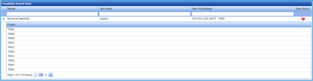
Figure 2.7.1: Feasibility Search Clear page
The page shows the feasibility search data of all the users.
2. Click  (Clear icon) of the respective user to clear the feasibility search data.
The feasibility search data of the selected user will be cleared.
2.8 Material Substitution
The Material Substitution tab in the Planning menu helps to substitute one item for another item. To perform the material substitution,
1. Click Material Substitution in the Planning
The Material Substitution page opens.
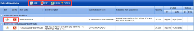
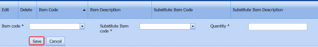
Figure 2.8: Material Substitution
2.8.1 Add Material Substitution
If you want to do material substitution,
1. Click  (ADD button) in the Material Substitution See Fig 5.8.
The page opens a new window to add the details of material substitution.
 Note: The field notified with a symbol (*) is mandatory. You must enter the relevant details in that field before saving.
2. In the Item Code box, select an item code from a drop-down list.
 Note: In the Item Code box, a list of item codes added in the BOM will be listed.
3. In the Substitute Item Code box, select a substitute item code from a drop-down list.
 Note: In the Substitute Item Code box, a list of item codes added in the inventory will be listed.
4. In the Quantity box, select the quantity of items you want to substitute.
5. Click Save.
The entered quantity of items will be substituted successfully. After completing the material substitution, you can do the feasibility search to check the feasibility percentage of the substituted materials.
2.8.2 Export Material Substitution List
You can export a list of material substitutions added in the Material Substitution page in the pdf and excel formats by using  (PDF button) and
  (Excel button). To know how to export, see the topic, “Export BOM List”.
2.8.3 Filter a Material Substitution
If you want to filter any material substitution from the list of material substitutions in the Material Substitution page, you can use
 (FILTER button). To know how to filter, see the topic, “Filter a BOM”.
2.9 Component Requirement
The Component Requirement tab in the Planning menu helps to add the components required for the items. To add the component requirement,
1. Click Component Requirement in the Planning
The Component Requirement page opens with a list of components.
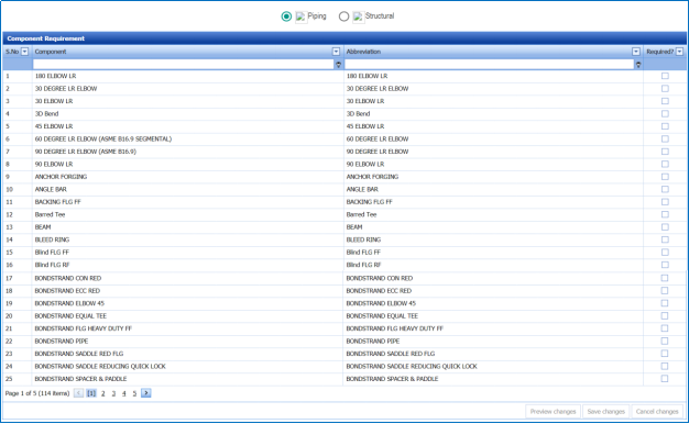
Figure 2.9: Component Requirement page
2. Select the module whether Piping or Structural.
3. Select the checkbox of the component you require.
4. Click Save changes.
2.10 Offcut Inventory
When a material issuance has been created with the Offcut material, we need to add the offcut material details in the Offcut inventory. To add the offcut material details,
1. Click Offcut Inventory in the Planning
The Offcut Inventory page opens.
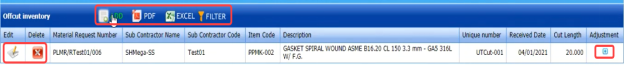
Figure 2.10: Offcut Inventory page
2.10.1 Add Offcut Material Detail
To add the offcut material detail,
1. Click  (ADD button) in the Offcut Inventory See Fig 5.10.
A new window opens to add the details of offcut material.
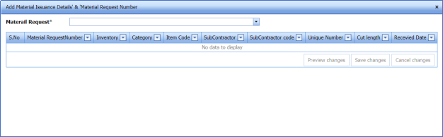
2. In the Material Request box, select a material request from a drop-down list.
The cut length for the selected material request opens.
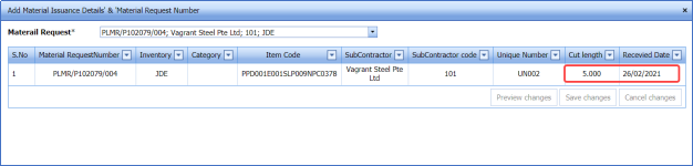
3. In the Cut Length column, change the cut length of the offcut item if you want.
 Note: The cut length should not be exceeded the material issuance quantity.
4. In the Received Date box, choose the date when the offcut material received in the Offcut inventory.
5. Click Save changes.
The offcut material is added.
2.10.2 Adjust Cut Length Quantity
To adjust the cut length quantity,
1. Click  (Add icon) in the Adjustment
The Adjustment window opens.
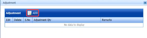
2. Click  (ADD button) in the Adjustment
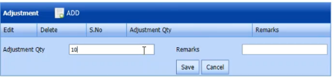
3. In the Adjustment Qty box, enter the adjustment cut length quantity.
4. In the Remarks box, enter your remarks if any.
5. Click Save.
The adjusted cut length quantity will be updated.
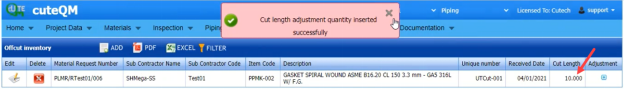
2.10.3 Export Offcut Inventory List
You can export a list of offcut materials added in the Offcut Inventory page in the pdf and excel formats by using
 (PDF button) and
  (Excel button). To know how to export, see the topic, “Export BOM List”.
2.10.4 Filter an Offcut Material
If you want to filter any offcut material from the list of offcut materials in the Offcut Inventory page, you can use
 (FILTER button). To know how to filter, see the topic, “Filter a BOM”.
2.11 Material Request
The Material Request tab in the Planning menu helps to manage the material requests added in the Feasibility page.
2.11.1 Add a Material Request
If you want to create a material request, do the following steps,
2. Select the checkbox of the project for which you want to add the material requests.
3. Click  (ADD MATERIAL REQUEST button).
The Sub con Details window opens.
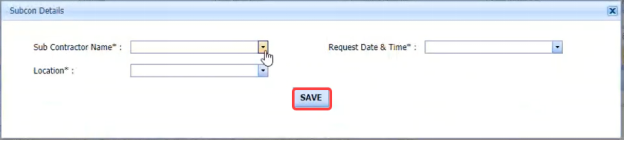
4. In the Sub Contractor Name box, select a sub-contractor.
5. In the Request Date & Time box, choose the request date and time.
6. In the Location box, select a location.
7. Click SAVE.
The material request will be added in the Material Request page.
 Note: For each item code included in the project, one material request will be created individually.
For example, The BOM quantity is 18 and you set the high priority for JDE and the least priority for Offcut. A material request will be created with the JDE inventory if the JDE has the same quantity of 18. If the JDE is available with quantity of 10, then two material requests will be created separately for quantity of 10 in JDE and quantity of 8 in Offcut.
8. Click Material Request in the Planning
The Material Request page opens and shows the list of created material requests.
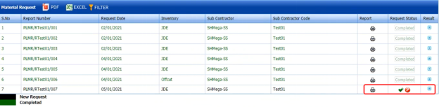
Figure 2.11: Material Request page
 Note: The material request displayed in different colors explains the status of the request.
- The material request displayed in Blue color indicates a new material request.
- The material request displayed in Green color indicates the completed material request.
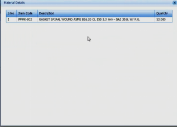
9. If you want to view the material details, click (Expand icon) of the respective request.
The Material Details window opens and shows the material details.
2.11.2 Approve a Material Request
Once you have added the material request, the Request Status column in the Material Request page is appeared with 
(Submit and Reject icons).
1. If you want to approve the material request, click  (Approve icon) in the Request Status Otherwise click
  (Reject icon) to reject the request.
The approved material request will be moved for Material Acceptance.
2.11.3 View a Material Request Report
If you want to view a material request report, click  (Report icon) provided in the Report column of the Material Request page.
2.11.4 Export Material Request List
You can export a list of material requests added in the Material Request page in the pdf and excel formats by using 
(PDF button) and  (Excel button). To know how to export, see the topic, “Export BOM List”.
2.11.5 Filter a Material Request
If you want to filter any material request from the list of material requests in the Material Request page, you can use 
2.12 Material Issuance
When a material request has been created with the Offcut inventory, we need to issue materials from the Offcut inventory for the created request.
 Note: You can do the material issuance process for materials only in the Offcut inventory.
The Material Issuance tab in the Planning menu helps to issue the materials from the Offcut inventory based on the added material request.
1. Click Material Issuance in the Planning
The Material Issuance page opens.
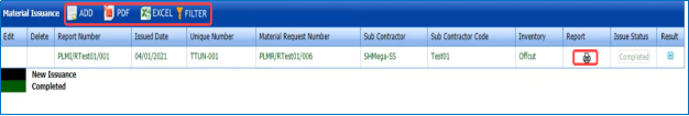
Figure 2.12: Material Issuance
2.12.1 Add a Material Issuance Report
If you want to add a material issuance report,
1. Click  (ADD button) in the Material Issuance See Fig 2.12.
The page opens a new window to add the details of material issuance.

 Note: The field notified with a symbol (*) is mandatory. You must enter the relevant details in that field before saving.
2. In the Material Request Number box, select a material request number from a drop-down list.
3. In the Issued Date box, choose the issued date.
4. Click Save.
The material issuance request will be added.
2.12.2 Add Issued Quantity
Once you have added the material issuance request, you must add the issued quantity details. To add,
1. Click  (Add icon) in the Result
The Material Details window opens.
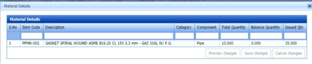
2. Check the available quantity in the Total Quantity
3. In the Issued Qty column, enter the issued quantity.
 Note: The issued quantity can be higher than the available total quantity for all type of components.
4. Click Save changes.
2.12.3 Approve a Material Issuance
Once you have added the material issuance, the Issue Status column in the Material Issuance page is appeared with 
(Submit and Reject icons).
1. If you want to approve the material issuance, click  (Approve icon) in the Issue Status Otherwise click
  (Reject icon) to reject the request.
The approved material issuance will be moved to Offcut Inventory.
2.12.4 View a Material Issuance Report
If you want to view a material issuance report, click  (Report icon) provided in the Report column of the Material Issuance page.
2.12.5 Export Material Issuance List
You can export a list of material issuances added in the Material Issuance page in the pdf and excel formats by using 
(PDF button) and  (Excel button). To know how to export, see the topic, “Export BOM List”.
2.12.6 Filter a Material Issuance
If you want to filter any material issuance from the list of material issuances in the Material Issuance page, you can use 
2.13 CNC Process
2.14 BOM Summary
The BOM Summary tab in the Planning menu helps to view the BOM status added against the module. To view the BOM status,
1. Click BOM Summary in the Planning
The BOM Status by ISO page opens and shows a list of modules with their cutting plan drawings.
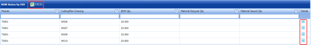
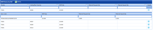
Figure 2.14: BOM Status by ISO page
2. Click  (Expand icon) in the Details
The page shows the items included in the respective module including the BOM quantity, material request quantity, and material issued quantity.
2.14.1 Export BOM Status
You can export the BOM generated in the BOM Status by ISO page in an excel format by using  (Excel button). To know how to export, see the topic, “Export BOM List”.
2.15 BOM Details
The BOM Details tab in the Planning menu helps to view the added BOM details. To view the BOM details,
1. Click BOM Details in the Planning
The BOM Details page opens.
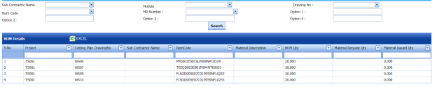
Figure 2.15: BOM Details page
2. If you want to view any particular BOM details, you can use the filter options (Explained below) given in the page,
- If you want to view the BOM details of any sub-contractor, select a sub-contractor in the Sub Contractor Name
- If you want to view the BOM details of any module, select a module in the Module
- If you want to view the BOM details against a drawing number, select a drawing number in the Drawing No
- If you want to view the BOM details for any item code, select an item code in the Item Code
- If you want to view the BOM details against a MR number, select a MR number in the MR Number
- The Option 1, Option 2, Option 3, and Option 4boxes are provided to filter the BOM details by giving the BOM description.
3. Click Search.
The BOM will be displayed based on the given data in the filter boxes.
2.15.1 Export BOM Details
You can export the BOM details generated in the BOM Details page in an excel format by using  (Excel button). To know how to export, see the topic, “Export BOM List”.
2.16 Fit up Production Joints
The Fit up Production Joints tab in the Planning menu helps you to add an RFI Fit up request.
1. Click Fit up Production Joints in the Planning
The Production – Joints (Structural Fit up) page opens and shows a list of added joints.
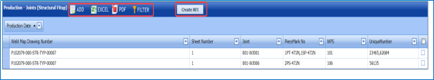
Figure 2.16: Production – Joints (Structural Fit up) page
2.16.1 Add New Joints
Before creating an RFI fit up request, you can add the joints. If you want to add a new joint, do the following steps.
1. Click  (ADD button) in the Production – Joints (Structural Fit up)
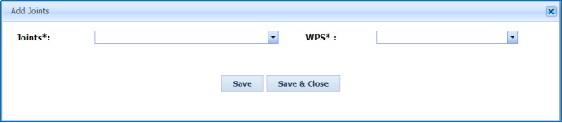
The Add Joints window opens.
 Note: The field notified with a symbol (*) is mandatory. You must enter the relevant details in that field before saving.
2. In the Joints box, select a joint from a drop-down list.
After the selection of joint, the Unique Number 1 and Piece Mark 1 boxes appear.
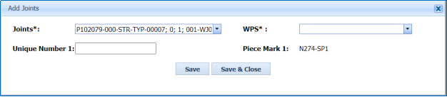
3. In the WPS box, select a WPS from a drop-down list.
4. In the Unique Number 1box, enter the unique number.
5. Click Save & Close.
The added joint will be listed in the Production – Joints (Structural Fit up) page.
2.16.2 Create an RFI Fit up Request
To create an RFI fit up request,
1. Select the checkbox of the joints for which you want to create an RFI fit up request.
2. Click  (Create RFI button).
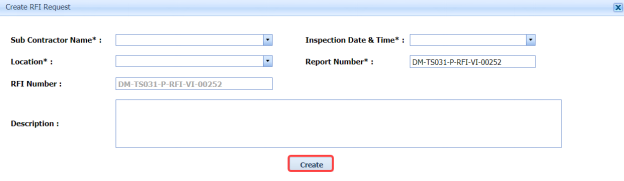
The Create RFI window opens.
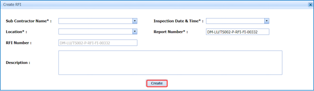
 Note: The field notified with a symbol (*) is mandatory. You must enter the relevant details in that field before saving.
3. In the Sub Contractor Name box, select a sub-contractor from a drop-down list.
4. In the Inspection Date & Timebox, choose the inspection date and time.
5. In the Location box, select a location from a list of locations.
6. In the Report Number box, edit/change the report number if you want.
7. In the Description box, enter the description for the request.
8. Click Create.
The added fit up request will be created successfully. The added fit up request will be moved to the View RFI Fit up tab in the Inspection menu. See Fig 4.1.

9. To view the added request,
The REQUEST FOR INSPECTION page opens and shows the added request.
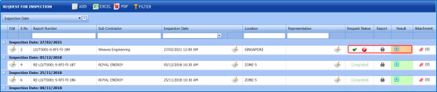
10. To submit the request, click  (Submit icon) in the Request Status
Once you have submitted the request, the result icon will be enabled in the Result column.
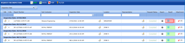
11. Click  (Result icon) and add your fit up inspection results.
2.16.3 Export Joints List
You can export a list of joints added in the Production – Joints (Structural Fit up) page in the pdf and excel formats by using
 (PDF button) and
  (Excel button). To know how to export, see the topic, “Export BOM List”.
2.16.4 Filter a joint
If you want to filter any joint from the list of joints in the Production – Joints (Structural Fit up) page, you can use
 (FILTER button). To know how to filter, see the topic, “Filter a BOM”.
2.17 Weld VI Production Joints
The Weld VI Production Joints tab in the Planning menu helps you to add a weld VI request.
1. Click Weld VI Production Joints in the Planning
The Production – Joints (Structural Weld VI) page opens and shows a list of added joints.
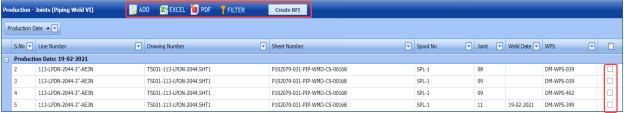
Figure 2.17: Production – Joints (Piping Weld VI) page
2.17.1 Add New Joints
Before creating a weld request, you should add the joints. If you want to add a new joint, do the following steps.
1. Click  (ADD button) in the Production – Joints (Piping Weld VI)
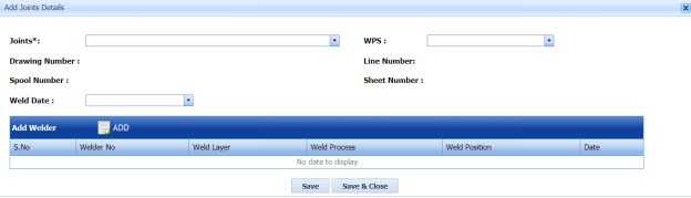
The Add Joints window opens.
 Note: The field notified with a symbol (*) is mandatory. You must enter the relevant details in that field before saving.
2. In the Joints box, select a joint from a drop-down list.
According to the selection of joints, the drawing number, line number, spool number, and sheet number will be updated.
3. In the WPS box, select a WPS from a drop-down list.
4. In the Weld Date box, choose the weld date.
5. In the Add Welder window, click  (ADD button).
A new field opens to add the welder details.
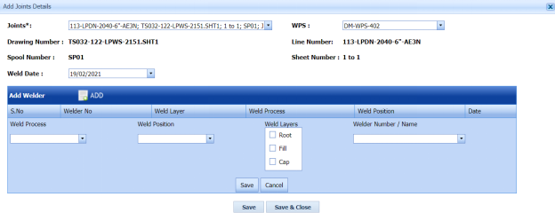
- In the Weld Process box, select a weld process.
- In the Weld Position box, select a weld position.
- In the Weld Layers box, select the checkbox of the weld layers.
- In the Welder Number / Name box, select a welder name and number.
- Click Save.
6. Click Save & Close.
The added joint will be listed in the Production – Joints (Piping Weld VI) page.
2.17.2 Create a Weld VI Request
To create a weld VI request,
1. Select the checkbox of the joints for which you want to create a weld VI request.
2. Click  (Create RFI button).
The Create RFI window opens.
 Note: The field notified with a symbol (*) is mandatory. You must enter the relevant details in that field before saving.
3. In the Sub Contractor Name box, select a sub-contractor from a drop-down list.
4. In the Inspection Date & Timebox, choose the inspection date and time.
5. In the Location box, select a location from a list of locations.
6. In the Report Number box, edit/change the report number if you want.
7. In the Description box, enter the description for the request.
8. Click Create.
The added weld VI request will be created successfully. The added weld VI request will be moved to the View RFI Weld VI tab in the Inspection menu. See Fig 4.1.
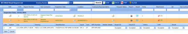
9. To view the added request, navigate to the View RFI Weld VI tab in the Inspection
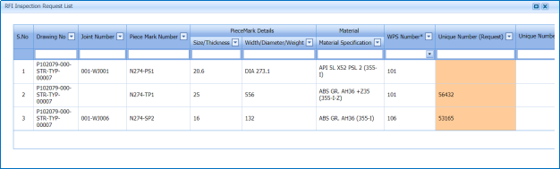
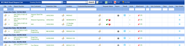
The RFI Weld Visual Request List page opens and shows the added weld VI request.
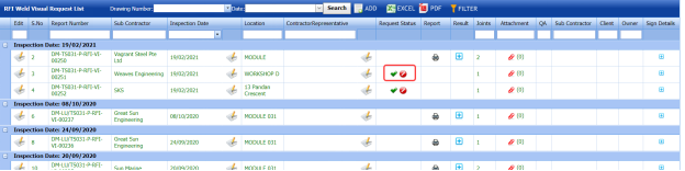
10. To submit the request, click  (Submit icon) in the Request Status
Once you have submitted the request, the result icon will be enabled in the Result column.
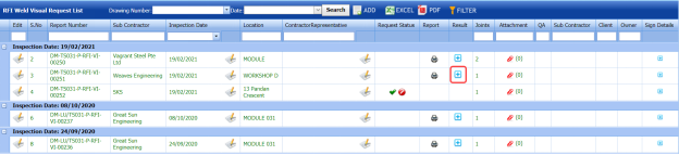
11. Click  (Result icon) and add your weld visual inspection results.
2.17.3 Export Joints List
You can export a list of joints added in the Production – Joints (Piping Weld VI) page in the pdf and excel formats by using
 (PDF button) and
  (Excel button). To know how to export, see the topic, “Export BOM List”.
2.17.4 Filter a joint
If you want to filter any joint from the list of joints in the Production – Joints (Piping Weld VI) page, you can use
 (FILTER button). To know how to filter, see the topic, “Filter a BOM”.
No Comments