
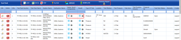
Test Pack (ISO)
7.1 Test Pack (ISO)
The Test Pack (ISO) tab in the Test Pack menu helps you to add a test back (ISO). To navigate to the test pack adding page,
- Click Test Pack (ISO) in the Test Pack menu. The Test Pack page opens.

Figure 7.1: Test Pack (ISO) page
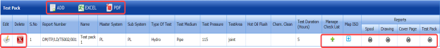
7.1.1 Add a Test Pack
If you want to add a test pack, do the following steps,
-
Click
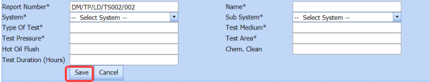
 (ADD button) in the Test Pack page. See Fig 7.1.
The page opens a new window to add the details of a test pack.

 Note: The field notified with a symbol (*) is mandatory. You must enter the relevant details in that fields before saving.
 Tip: A report number for a new test pack will be updated automatically in the Report Number box. If you want to change the report number, you can change.
 -
In the System box, select a system from a drop-down list.
-
In the Name box, enter the name of the test pack.
-
In the Sub System box, select a sub system from a drop-down list.
-
In the Type of Test box, enter the type of test.
-
In the Test Medium box, enter the name of a test medium.
-
In the Test Pressure box, enter the test pressure value.
-
In the Test Area box, enter the name of a test area.
-
In the Hot Oil Flush box, enter the detail of hot oil flush.
-
In the Chem. Clean box, enter the detail of chemical cleaning.
-
In the Test Duration (Hours) box, enter the duration of test.
-
Click Save.
The test pack is successfully added and listed in the Test Pack page. Once you have added a test pack, you can manage the checklist of MCR and map ISO drawings/spool for the added test pack.


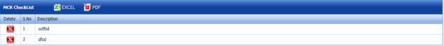
7.1.2 Manage a Checklist
If you want to manage the checklist of test pack,
- Click (Add icon) in the Manage Checklist See Fig 7.1.
The page redirects you to the Checklist Name page.

-
Click
 (ADD button) in the Checklist Name page.
The page opens a new window to add the details of the checklist.
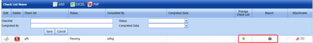
-
In the Checklist box, enter the checklist name.
-
In the Status box, select the status of the checklist.
-
In the Completed by box, enter the name of a person who has completed checklist.
-
In the Completed Date box, select the completed date of the checklist.
-
Click Save.
The added checklist will be listed in the Checklist Name page.
- If you want to manage the added checklist, click (Add icon) in the Manage Checklist column of the Checklist Name page.
The MCR Checklist page opens for the selected checklist.
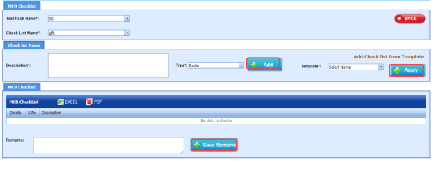
-
In the Description box, enter the description for the checklist you want to add.
- In the Type box, select the checklist type and click
 .
.
The added checklist will be listed in the MCR Checklist window.
- If you want to add the checklists from a template, in the Template box, select the template from a drop-down list and click
 .
.
The checklists in the template will be listed in the MCR Checklist window.
-
In the Remarks box, enter your remarks.
-
Click
 .
.


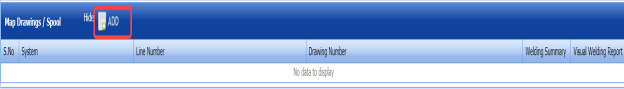
7.1.3 Map ISO
If you want to map ISO drawings/ spool for the added test pack, do the following steps,
- Click
 (Add icon) in the Map ISO column of the respective test pack.
The Map Drawings/Spool window opens.

- Click
 (ADD button) in the Map Drawings/Spool window.
The window shows a list of drawing and their spools.
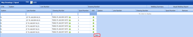
- Do one of the following steps to add spools,
-
-
If you want to add a spool, click
 (Add icon) provided in the Add column.
The added spools will be moved to right side of the window.
- If you want to add all spools in the drawing, click
 (Add icon) provided in the Drawing Number column.
The added spools will be moved to right side of the window.
-
-
-
Click Save.
The added spools will be listed in the in the Map Drawings/Spool window.
-
-
If you want to view a weld inspection summary report, click
 (print icon) provided in the Welding Summary column.
 -
If you want to view a visual welding report, click
 (print icon) provided in the Visual Welding Report column.
-
-


7.1.4 Edit a Test Pack
If you want to edit any added test pack in the Test Pack page,
- Click
 (Edit icon) of the respective test pack. See Fig 7.1.
The Test Pack page shows the details of the selected test pack.
-
Edit the details where you want.
-
Click Save.

7.1.5 Delete a Test Pack
If you want to delete any existing test pack in the Test Pack page, you can use  (Delete icon) provided in the Test Pack page. To know how to delete, see the topic, “Delete P&ID”.
7.1.6 View a Test Pack Spool List Report
If you want to view a test pack spool list report, click  (print icon) provided in the Spool column.
7.1.7 View a Drawing List Report
If you want to view a drawing list report, click (print icon) provided in the Drawing column.
7.1.8 View a Cover Page of Test Pack
If you want to view a cover page of test pack, click  (print icon) provided in the Cover Page column.
7.1.9 View a Test Pack Report
If you want to view a test pack report, click  (print icon) provided in the Test Pack column.
7.1.10 Export Test Pack list
You can export a list of test packs added in the Test Pack page in both the pdf and excel formats by using  (PDF button) and
  (Excel button). To know how to export, see the topic, “Export P&ID list”.
7.2 Test Pack (Spool)
The Test Pack (Spool) tab in the Test Pack menu helps you to add a test back (Spool). To navigate to the test pack adding page,
- Click Test Pack (Spool) in the Test Pack menu.
The Test Pack page opens.

Figure 7.2: Test Pack page
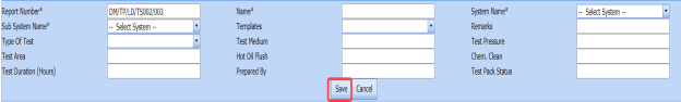
7.2.1 Add a Test Pack
If you want to add a test pack, do the following steps,
- Click
 (ADD button) in the Test Pack See Fig 7.2.
The page opens a new window to add the details of a test pack.
 Note: The field notified with a symbol (*) is mandatory. You must enter the relevant details in that fields before saving.
 Tip: A report number for a new test pack will be updated automatically in the Report Number box. If you want to change the report number, you can change.
 -
In the System Name box, select a system from a drop-down list.
-
In the Name box, enter the name of the test pack.
-
In the Sub System Name box, select a sub system from a drop-down list.
-
In the Type of Test box, enter the type of test.
-
In the Templates box, select a template from a drop-down list.
-
In the Remarks box, enter your remarks if any.
-
In the Test Medium box, enter the name of a test medium.
-
In the Test Pressure box, enter the test pressure value.
-
In the Test Area box, enter the name of a test area.
-
In the Hot Oil Flush box, enter the detail of hot oil flush.
-
In the Chem. Clean box, enter the detail of chemical cleaning.
-
In the Test Duration (Hours) box, enter the duration of test.
-
In the Prepared By box, enter the name of a person who has prepared the test pack.
-
In the Test Pack Status box, enter the status of the test pack.
-
Click Save.
The test pack is successfully added and listed in the Test Pack page. Once you have added a test pack, you can manage the checklist and assign spools and components for the added test pack.
 Note: If you want to perform the above tasks, click
  (Add icon) in the Assign Spool/ Components column of the respective test pack.
The page shows the Manage Checklist, Assign Spool, and Assign Component options.


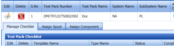
7.2.2 Manage a Checklist
If you want to manage the test pack checklist, Click the Manage Checklist option.
The Test Pack Checklist window opens.

If you want to edit any checklist, you can edit the checklist.
7.2.3 Assign a Spool
If you want to assign spool for the added test pack, do the following steps,
- Select the Assign Spool option.
The Assign Spool window opens.
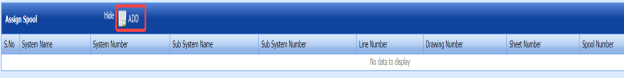
-
Click
 (ADD button) in the Assign Spool window.
The window shows a list of spools.
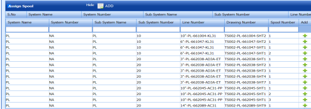
- If you want to add a spool, click
 (Add icon) provided in the Add column.
 -
Click Save.
The added spools will be listed in the in the Assign Spool window.


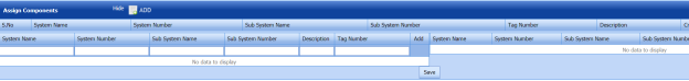
7.2.4 Assign a Component
If you want to assign a component, click the Assign Component option.
The Assign Component window opens.
7.2.5 Add Test Pack Result
After completing the spool test for the added test pack request, you can add the result details. To add results, do the following steps,
- Click
 (Add icon) in the Result column of the Test Pack See Fig 7.2.
The Test Package window opens.


The Test Package window contains the following options: Index, Pre-Pressure Checklist, Pressure Test, Final Review, Flushing Test, Content, Work instruction, Pre-Checklist, Punch List, Weld Inspection, Hydro Test Report, Flushing Check, BP Test, Instrument List, and Post Checklist.


Index
If you want to add index for the test pack,
- Click Index option.
The Index window opens with a list of contents.
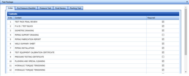
-
Select the contents which you want to add in the Index.

Pre-Pressure Checklist
If you want to add pre-pressure checklist for the test pack,
- Click Pre-Pressure Checklist option.
The Pre-Pressure Checklist window opens with a list of checklists.
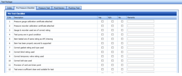
-
Select the checklists which you want to add.
-
-
If you want to add the checklist, select the checkbox in the Yes column for the respect checklist.
- If the checklist is not applicable, select the checkbox in the N/A column.
- If you do not want to any checklist, select the checkbox in the No column for the respect checklist.
-
-

Pressure Test
If you want to add pressure test results,
- Click Pressure Test option.
The Pressure Test window opens with the following boxes: ISO List, Test Description, and Test Equipment.
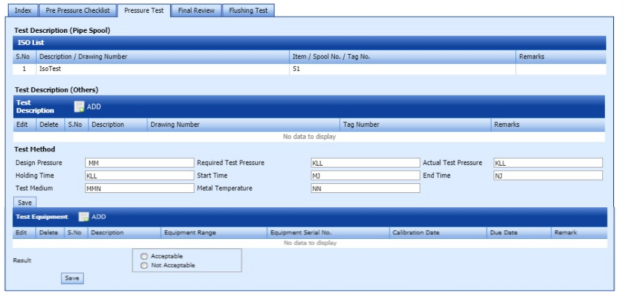
-
In the Test Description box, click
 (ADD button).
The Test Method box opens.
-
-
In the Design Pressure box, enter the design pressure value.
-
In the Required Test Pressure box, enter the required test pressure value.
-
In the Actual Test Pressure box, enter the actual test pressure value.
-
In the Holding Time box, enter the holding time range.
-
In the Start Time box, enter the start time of the pressure test.
-
In the End Time box, enter the end time of the pressure test.
-
In the Test Medium box, enter the test medium name.
- In the Metal Temperature box, enter the metal temperature value.
-
Click Save.
-
-
- In the Result field, select the result of the pressure test whether Acceptable or Not Acceptable.
-
Click Save.


Final Review
If you want to view the final review of the test pack,
- Click Final Review option.
The Final Review window opens with the final review report.
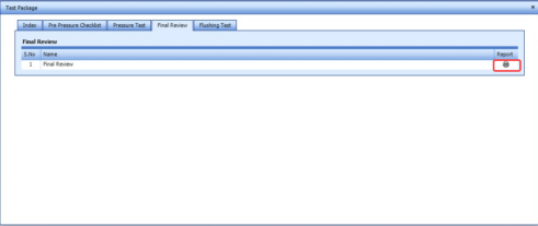
-
If you want to view the final review report, click
 (print icon).


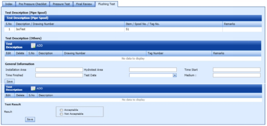
Flushing Test
If you want to add flushing test results,
- Click Flushing Test option.
The Flushing Test window opens with the following boxes: Test Description (Pipe Spool), Test Description, and Test Equipment.
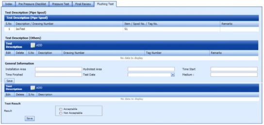
-
In the Test Description (Others) box, click
 (ADD button).
The General Information box opens.
-
-
In the Installation Area box, enter the installation area value.
-
In the Hydrotest Area box, enter the hydrotest area value.
-
In the Start Time box, enter the start time of the flushing test
-
In the Time Finished box, enter the finished time of the flushing test.
-
In the Test Date box, select the date of flushing test.
-
In the Test Medium box, enter the test medium name.
-
Click Save.
-
-
- In the Test Result field, select the result of the pressure test whether Acceptable or Not Acceptable.
-
Click Save.

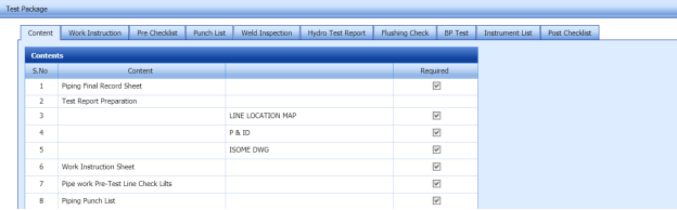
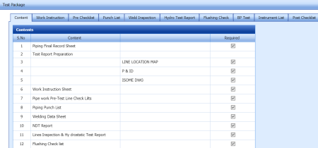
Content
If you want to add content for the test pack,
-
Click Content option.
The Contents window opens with a list of contents.
-
Select the contents which you want to add in the Content.

Work Instruction Sheet
If you want to add the work instruction,
- Click Work Instruction Sheet option.
The Work Instruction Sheet window opens.
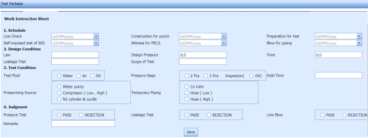
-
In the Schedule field, enter the work schedule details.
-
In the Design Condition field, enter the design condition details.
-
In the Test Condition field, enter the test condition details.
-
In the Judgement field, enter the judgement details.
-
Click Save.

Pre-Test Checklist
If you want to add pre-test checklist for the test pack,
- Click Pre-Test Checklist option.
The Pre-Test Checklist window opens with a list of checklists.
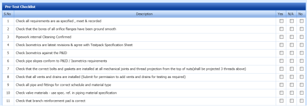
- Select the checklists which you want to add.
-
- If you want to add the checklist, select the checkbox in the Yes column for the respect checklist.
-
If the checklist is not applicable, select the checkbox in the N/A column.
- If you do not want to any checklist, select the checkbox in the No column for the respect checklist.
-

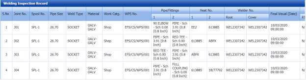
Welding Inspection Record
If you want to view the welding inspection record,
-
Click Welding Inspection Record option.
The Welding Inspection Record window shows the welding inspection record.

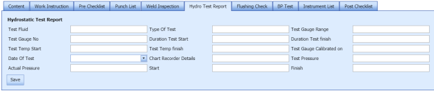
Hydro Test Report
If you want to add the hydro test report,
- Click Hydro Test Report option.
The Hydrostatic Test Report window shows a new window to add the hydrostatic test report details.

-
In the Test Fluid box, enter the test fluid name.
-
In the Type of Test box, enter the test type.
-
In the Test Gauge Range box, enter the test gauge range.
-
In the Test Gauge No box, enter the test gauge number.
-
In the Duration Test Start box, enter the test starting time.
-
In the Duration Test Finish box, enter the test finishing time.
-
In the Date of Test box, select the test date.
-
In the Test Pressure box, enter the test pressure value.
-
In the Actual Pressure box, enter the actual pressure value.
-
Click Save.
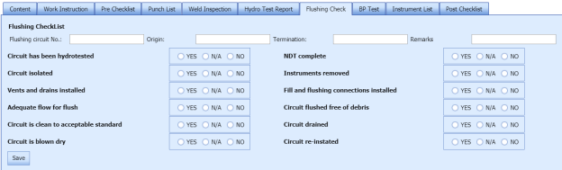
Flushing Check List
If you want to add the flushing check list,
- Click Flushing Check List option.
The Flushing Check List window shows a new window to add the flushing check list details.

-
In the Flushing Circuit No box, enter the flushing circuit number.
-
In the Origin box, enter the origin name.
-
In the Termination box, enter the termination detail.
-
In the Remarks box, enter your remarks if any.
-
Select the appropriate checklist.
-
Click Save.
BP List
If you want to add the BP list detail,
- Click BP List option.
The BP List window shows a new window to add the BP list details.
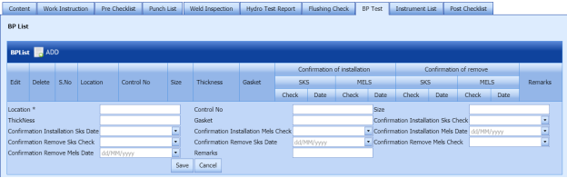
-
Click
 (ADD button) in the BP List window.
 -
In the Location box, enter the location name.
-
In the Control No box, enter the control number.
-
In the Size box, enter the size vale.
-
In the Thickness box, enter the thickness value.
-
In the Gasket box, enter the gasket detail.
-
Click Save.


Instrument List
If you want to add the instrument list detail,
- Click Instrument List option.
The Instrument List window shows a new window to add the instrument list details.
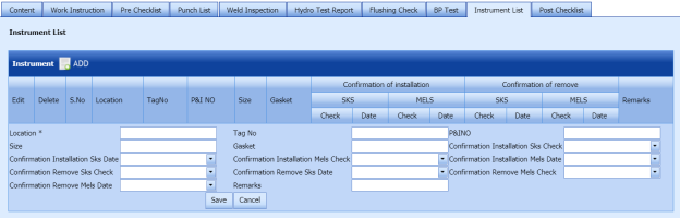
-
Click
 (ADD button) in the Instrument List window.
 -
In the Location box, enter the location name.
-
In the Tag No box, enter the tag number.
-
In the P&I No box, enter the P&I number.
-
In the Size box, enter the size vale.
-
In the Gasket box, enter the gasket detail.
-
In the Remarks box, enter your remarks if any.
-
Click Save.


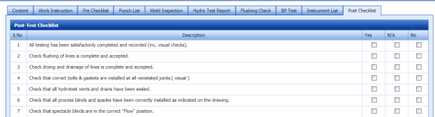
Post-Test Checklist
If you want to add post-test checklist for the test pack,
- Click Post-Test Checklist option.
The Post-Test Checklist window opens with a list of checklists.

- Select the checklists which you want to add.
-
- If you want to add the checklist, select the checkbox in the Yes column for the respect checklist.
-
If the checklist is not applicable, select the checkbox in the N/A column.
- If you do not want to any checklist, select the checkbox in the No column for the respect checklist.
-
7.2.6 Edit a Test Pack
If you want to edit any added test pack in the Test Pack page,
-
Click
 (Edit icon) of the respective test pack. See Fig 7.2.
The Test Pack page shows the details of the selected test pack.
-
Edit the details where you want.
-
Click Save.

7.2.7 Delete a Test Pack
If you want to delete any existing test pack in the Test Pack page, you can use  (Delete icon) provided in the Test Pack page. To know how to delete, see the topic, “Delete P&ID”.
7.2.8 View a Test Pack MDR Report
If you want to view a test pack MDR report, click  (print icon) provided in the Assign Spool/Components column.
7.2.9 Attach a File into a Test Pack
If you want to attach any file with any test pack listed in the Test Pack page, you can attach the file by using (Attach icon) in the Attachment column. To know how to attach, follow the procedures given in the topic “Attach a file into P&ID”.
7.2.10 Export Test Pack list
You can export a list of test packs added in the Test Pack page in both the pdf and excel formats by using  (PDF button) and
  (Excel button). To know how to export, see the topic, “Export P&ID list”.
7.2.11 Filter a Test Pack
If you want to filter any specific test pack in the Test Pack page, you can use  (FILTER button) located on the Test Pack page. To know how to filter, see the topic, “Filter P&ID”.
7.2.12 Import Multiple Test Packs
If you want to import multiple test packs together, do the following,
- Click
 (TEMPLATE button). See Fig 7.2.
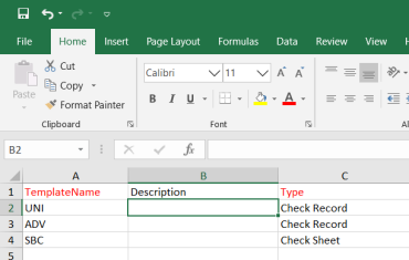
An excel worksheet will be downloaded with a predefined template to enter the details of systems.

-
Enter the required test pack details in the respective columns of the excel worksheet.
- Once you have added the test pack details in the excel worksheet, save the excel worksheet on your computer.
-
Click
 (IMPORT button). See Fig 7.2.
A new window opens for importing the excel worksheet saved on your computer.

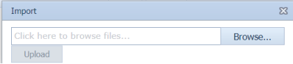
-
Click
 (Browse button) to select the excel worksheet to be uploaded.
 -
Select the excel worksheet you want to upload from your computer.
-
Click
 (Upload button) to export the test pack details that are included in the excel worksheet.


The details of the test packs in the worksheet will be displayed in the Test Pack page.
7.2.13 View a Test Pack Summary Report
If you want to view a test pack summary report, click (Summary Report icon) provided in the Test Pack page.
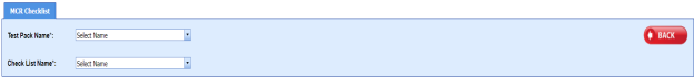
7.3 Test Pack Checklist
The Test Pack Checklist tab in the Test Pack menu helps you add the checklist items for the specific test pack. To add the checklist,
- Click Test Pack Checklist in the Test Pack menu.
The MCR Checklist page opens.

-
In the Test Pack Name box, select the test pack name from a drop-down list.
-
In the Checklist Name box, select a checklist from a drop-down list.
The Checklist Items and MCR Checklist windows open.
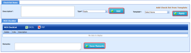
-
In the Description box, enter the description for the checklist you want to add.
-
In the Type box, select the checklist type and click
 .
.The added checklist will be listed in the MCR Checklist window.

- If you want to add the checklists from a template, in the Template box, select the template from a drop-down list and click
 .
.
The checklists in the template will be listed in the MCR Checklist window.
- In the Remarks box, enter your remarks.
-
Click
 .
.


7.4 MCR Checklist Template
The MCR Checklist Template tab in the Test Pack menu helps you to add MC/SC – Check Record (CR)/Check Sheet (CS) templates. To navigate to the templates adding page,
-
Click MCR Checklist Template in the Test Pack menu.
The MC/SC – CR/CS Templates page opens.

Figure 7.4: MC/SC – CR/CS Templates page
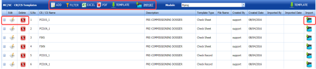
7.4.1 Add a CR/CS Template
If you want to add a CR/CS template,
-
Click
 (ADD button) in the MC/SC – CR/CS Templates page. See Fig 7.4.
The page opens a new window to add the details of a test pack.

 Note: The field notified with a symbol (*) is mandatory. You must enter the relevant details in that fields before saving.
 - In the CR/CS Name box, enter the name for CR/CS.
- In the Template Type box, select a template whether CR or CS.
-
In the Description box, enter the description for CR/CS.
-
Click Save.
The template is successfully added and listed in the MC/SC – CR/CS Templates page. Once you have added the template details, you must import the respective template.


7.4.2 Import a CR/CS Template
If you want to import CR/CS template,
- Click
 (Add icon) of the respective CR/CS name in the MC/SC – CR/CS Templates page.
The Check Records window opens.
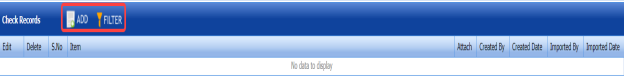
-
Click
 (ADD button) in the Check Records window.
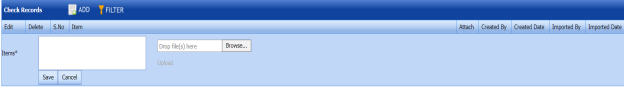
-
In Items box, enter the details of items.
-
Browse and attach a CS/CR template you want to import.
-
Click Save.


7.4.3 Edit a CR/CS Template
If you want to edit any added CR/CS template in the MC/SC – CR/CS Templates page,
- Click
 (Edit icon) of the respective CR/CS template. See Fig 7.4.
The MC/SC – CR/CS Templates page shows the details of the selected CR/CS template.
-
Edit the details where you want.
-
Click Save.

7.4.4 Delete a CR/CS Template
If you want to delete any existing CR/CS template in the MC/SC – CR/CS Templates page, you can use  (Delete icon) provided in the MC/SC – CR/CS Templates page. To know how to delete, see the topic, “Delete P&ID”.
7.4.5 Export CR/CS Template list
You can export a list of CR/CS templates added in the MC/SC – CR/CS Templates page in both the pdf and excel formats by using  (PDF button) and
  (Excel button). To know how to export, see the topic, “Export P&ID list”.
7.4.6 Filter a CR/CS Template
If you want to filter any specific CR/CS template in the MC/SC – CR/CS Templates page, you can use  (FILTER button) located on the Test Pack page. To know how to filter, see the topic, “Filter P&ID”.
7.4.7 Import Multiple CR/CS Templates
If you want to import multiple CR/CS templates together, do the following,
- Click
 (TEMPLATE button). See Fig 7.4.
An excel worksheet will be downloaded with a predefined template to enter the details of CR/CS templates.

-
Enter the required CR/CS template details in the respective columns of the excel worksheet.
- Once you have added the CR/CS template details in the excel worksheet, save the excel worksheet on your computer.
- Click
 (IMPORT button). See Fig 7.4.
A new window opens for importing the excel worksheet saved on your computer.

-
Click
 (Browse button) to select the excel worksheet to be uploaded.
 -
Select the excel worksheet you want to upload from your computer.
-
Click
 (Upload button) to export the CR/CS template details that are included in the excel worksheet.


The details of the CR/CS templates in the worksheet will be displayed in the MC/SC – CR/CS Templates page.
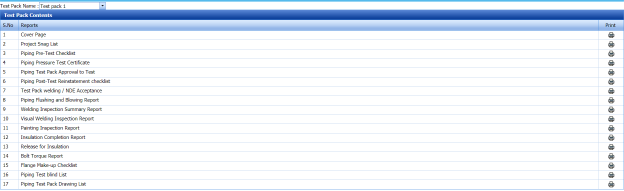
7.5 Test Pack Contents
The Test Pack Contents page used to view a list of reports of the documents included in the Test Pack. To view the test pack content’s report,
- Click Test Pack Contents in the Test Pack menu.
The Test Pack Contents page opens.

Figure 7.5: Test Pack Contents page
-
In the Test Pack Name box, select a test pack from a drop-down list.
The Test Pack Contents page shows a list of reports in the selected test pack.
 Note: If you want to view any specific report, click the respective (Print icon) in the Print column.

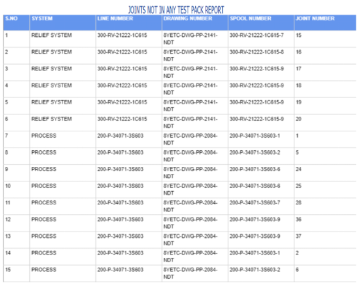
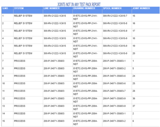
7.6 Joints Not in Any Test Pack Report
The Joints Not in Any Test Pack Report tab in the Test Pack menu shows a list of joints not added in any test pack report. To view of the details of joints,
- Click Joints Not in Any Test Pack Report in the Test Pack menu.
-
The Joints Not in Any Test Pack Report page opens with a list of joints, which are not added in any test pack report.
7.7 Overall Status
The Overall Status tab in the Test Pack menu helps you to view the overall status of NDT inspection, welding progress and piping. To view the overall status,
-
Click Overall Status in the Test Pack menu.
The page shows the overall status.


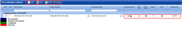
7.8 Acid Pickling Certificate
Pickling is a metal surface treatment used to remove impurities such as stains, inorganic contaminants, rust or scale from ferrous metals, copper, precious metals and aluminum alloys. A solution called pickle liquor, which usually contains acid, is used to remove the surface impurities.
The Acid Pickling Certificate tab in the Test Pack menu used to add the acid pickling certificate. To add the acid pickling certificate, do the following steps,
- Click Acid Pickling Certificate in the Test Pack menu.
The View Acid Pickling Certificate page opens.

Figure 7.8: View Acid Pickling Certificate page
7.8.1 Add an Acid Pickling Certificate
If you want to add an acid pickling certificate, do the following steps,
- Click
 (ADD button) in the View Acid Pickling Certificate page.
The ACID PICKLING page opens.
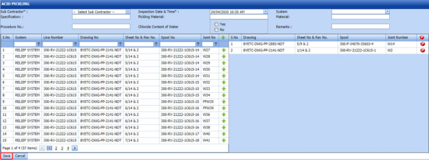
-
In the Sub Contractor box, select a sub-contractor from a drop-down list.
-
In the Inspection Date & Time box, select the inspection date and time.
-
In the Specification box, enter the specification.
-
In the Pickling Material box, enter the name of the pickling material.
-
In the System Material box, select the system material.
-
In the Procedure No box, enter the procedure number.
- If you use the chloride content of water for the acid pickling testing, select Yes in the Chloride Content of Water option otherwise select No.
-
In the Remarks box, enter your remarks if any.
Before saving the added acid pickling certificate, you must add joints for the acid pickling certificate.
 Note: You can add multiple joints for one acid pickling certificate.
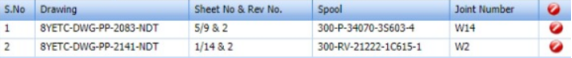
The ACID PICKLING page shows a list of joints for the corresponding line and drawing numbers including the spool number. If you want to add joints for the acid pickling certificate, do the following steps,
- Click
 (Add icon) of the respective joints you want to add.
The added joints will be moved and listed in the right side of the page.

-
Click Save.
The acid pickling certificate will be added and listed in the View Acid Pickling Certificate page.


7.8.2 Edit an Acid Pickling Certificate
If you want to edit any existing acid pickling certificate added in the View Acid Picking Certificate page, do the following steps,
- Click
 (Edit icon) in the Edit column for the respective acid pickling certificate. See Fig 10.8.
The ACID PICKLING page opens with the details of the selected acid pickling certificate.
-
Click any box where you want to edit the details, and then edit the details in the respective box.
-
Click Save.

7.8.3 Approve an Acid Pickling Certificate
Once you have added the acid pickling certificate, the Request Status column in the View Acid Pickling Certificate page is appeared with (Approve and Reject icons).
- If you want to approve the acid pickling certificate, click
 (Approve icon) in the Request Status column. Otherwise click
  (Reject icon) to reject the certificate.


7.8.4 Add RFI Data for an Acid Pickling Certificate
If you want to add the details of RFI data for the added acid pickling certificate, do the following steps,
- Click
 (Edit icon) in the RFI Data column of the View Acid Pickling Certificate See Fig 7.8.
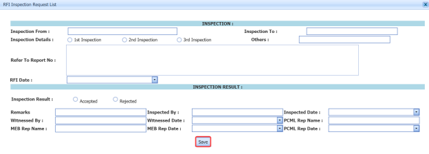
The RFI Inspection Request List window opens.
-
In the Inspection From box, enter the detail from where the inspection should start.
-
In the Inspection To box, enter the detail to where the inspection should end.
- In the Inspection Details option, select 1stInspection, 2nd Inspection or 3rd Inspection according to the inspection details.
-
In the Others box, enter any other inspection related details.
-
In the Refer to Report No box, enter the report number for reference.
-
In the RFI Date box, choose the RFI date.
- In the Inspection Result option, if the inspection result is accepted, select Accepted otherwise select Rejected.
- In the Remarks box, enter your remarks if any.
-
In the Inspected by box, enter the name of a person who has done inspection.
-
In the Inspected Date box, choose the date of inspection.
-
In the Witnessed By box, enter the name of the witnessed person.
-
In the Witnessed Date box, choose the date of witnessed.
-
In the PCML Rep Name box, enter the representative name of PCML.
-
In the PCML Rep Date box, choose the PCML rep date.
-
In the MEB Rep Name box, enter the representative name of MEB.
-
In the MEB Rep Date box, choose MEB rep date.
-
Click Save.


The RFI data for the acid pickling certificate is added successfully.
7.8.5 View an RFI Report for Acid Pickling Certificate
If you want to view an RFI report for the acid pickling certificate, click  (print icon) provided in the RFI Report column of the View Acid Pickling Certificate page. See Fig 7.8.
7.8.6 View an Acid Pickling Report
If you want to view the acid pickling report, click  (print icon) provided in the Print column of the View Acid Pickling Certificate page. See Fig 7.8.
7.8.7 Add Result for Acid Pickling Test
After completing the acid pickling test for the added request, you can add the result details. To add results, do the following steps,
- Click
 (Edit icon) in the RFI Data column of the View Acid Pickling Certificate page.
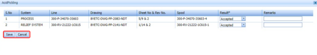
The Result window opens a list of systems added for the particular request.

-
In the Result column, select the result of each system from the given result options in the drop-down list.
-
In the Remarks column, enter your remarks if any.
-
Click Save.

7.8.8 Attach a File into an Acid Pickling Certificate
If you want to attach a file with any acid pickling certificate listed in the View Acid Pickling Certificate page, you can attach the file by using  (Attach icon) in the Attachment column. To know how to attach, follow the procedures given in the topic “Attach a file into P&ID”.
7.8.9 Export Acid Pickling Certificate List
You can export a list of acid pickling certificates added in the View Acid Pickling Certificate page in both the pdf and excel formats by using  (PDF button) and
  (Excel button). To know how to export, see the topic, “Export P&ID list”.
7.8.10 Filter an Acid Pickling Certificate
If you want to filter any specific acid pickling certificate in the View Acid Pickling Certificate page, you can use  (FILTER button) located on the View Acid Pickling Certificate page. To know how to filter, see the topic, “Filter P&ID”.
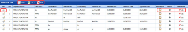
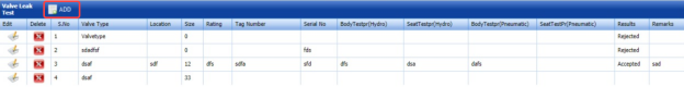
7.9 Valve Leak Test Record
All valves are inspected and tested by the inspectors to ensure that they conform to the required valve leakage standards. Valve leakage is tested using either a hydrostatic test that is the test medium is a liquid, such as water or kerosene, or a pneumatic test that is the test medium is a gas, such as air or nitrogen.
The Valve Leak Test Record tab in the Test Pack menu used to add the valve leak test report. To add the valve leak test report, do the following steps,
- Click Valve Leak Test Record in the Test Pack menu.
The Valve Leak Test page opens.

Figure 7.9: Valve Leak Test page
7.9.1 Add a Valve Leak Test Report
If you want to add a valve leak test report, do the following steps,
- Click
 (ADD button) in the Valve Leak Test page.
A new window opens to add the details of the valve leak test report.

 Note: The fields notified with a symbol (*) are mandatory. You must enter the relevant details in that fields before saving.
 Tip: A report number for a new valve leak test report will be updated automatically in the Report Number box. If you want change the report number, you can change.
 -
In the Test Pack box, select a test pack from a drop-down list.
-
In the Specification box, enter the specification.
- In the Prepared By box, enter the name a person who has prepared the valve leak test report.
- In the Prepared Date box, enter the prepared date of the valve leak test report.
- In the Reviewed By box, enter the name a person who has reviewed the valve leak test report.
- In the Reviewed Date box, enter the reviewed date of the valve leak test report.
-
In the Approved By box, enter the name a person who has approved the valve leak test report.
- In the Approved Date box, enter the approved date of the valve leak test report.
-
Click Save.


The valve leak test report will be added and listed in the Valve Leak Test page.
7.9.2 Edit a Valve Leak Test Report
If you want to edit any existing valve leak test report added in the Valve Leak Test page, do the following steps,
- Click
 (Edit icon) in the Edit column for the respective valve leak test report. See Fig 7.9.
The Valve Leak Test page opens with the details of the selected valve leak test report.
- Click any box where you want to edit the details, and then edit the details in the respective box.
-
Click Save.

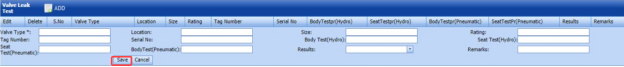
7.9.3 Add Result for Valve Leak Test
After completing the valve leak test, you can add the test result details. To add results, do the following steps,
- Click
 (Edit icon) in the Edit Report column of the Valve Leak Test page.
The Result window opens.

-
Click (Add button).

-
In the Valve Type box, enter the type of the valve.
-
In the Location box, enter the location of the valve.
-
In the Size box, enter the size of the valve.
-
In the Rating box, enter the rating of the valve.
-
In the Tag Number box, enter the tag number of the valve.
-
In the Serial No box, enter the serial number of the valve.
-
In the Body Test (Hydro) box, enter the detail of hydrostatic valve body test.
-
In the Seat Test (Hydro) box, enter the detail of the hydrostatic valve seat test.
-
In the Body Test (Pneumatic) box, enter the detail of pneumatic valve body test.
-
In the Seat Test (Pneumatic) box, enter the detail of the pneumatic valve seat test.
-
In the Results box, select the results whether Accepted or Rejected.
-
In the Remarks box, enter your remarks if any.
-
Click Save.

7.9.4 View a Valve Leak Test Report
If you want to view the valve leak test report, click  (print icon) provided in the Report column of the Valve Leak Test page. See Fig 7.9.
7.9.5 Attach a File into a Valve Leak Test Report
If you want to attach a file with any valve leak test report listed in the Valve Leak Test page, you can attach the file by using  (Attach icon) in the Attachment column. To know how to attach, follow the procedures given in the topic “Attach a file into P&ID”.
7.9.6 Export Valve Leak Test Report List
You can export a list of valve leak test reports added in the Valve Leak Test page in both the pdf and excel formats by using  (PDF button) and
  (Excel button). To know how to export, see the topic, “Export P&ID list”.
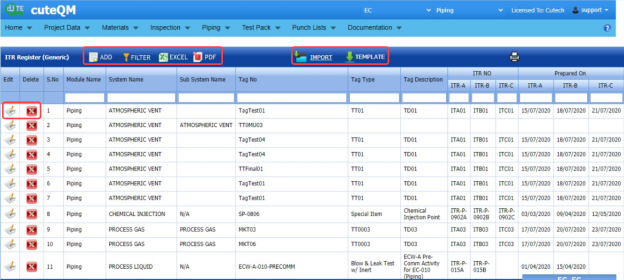
7.10 ITR Register (Generic)
The ITR Register (Generic) tab in the Test Pack menu used to add the ITR register.
-
Click ITR Register (Generic) in the Test Pack menu.
The ITR Register (Generic) page opens.

Figure 10.10: ITR Register (Generic) page
7.10.1 Add an ITR Register
If you want to add an ITR Register,
- Click (Add button) in the ITR Register (Generic) page.
The ITR Register (Generic) page opens a new window to add the details of the ITR register.

-
In the System box, enter the system name.
-
In the Sub System box, enter the subsystem name.
-
In the Tag No box, enter the tag number.
-
In the Tag Type box, enter the tag type.
-
In the Tag Description box, enter the tag description.
The page shows three options such as ITR-A Check Sheet (Construction), ITR-B Check Sheet (Pre-Commissioning), ITR-C Check Sheet (Commissioning).
You must add the following details for each option individually.
-
In the ITR No box, enter the ITR number for each option.
-
In the Prepared by MEB box, select the prepared date of ITR register for each option.
-
In the Submitted to Client box, select the submitted date of ITR register for each option.
-
In the Accepted to Client box, select the accepted date of ITR register for each option.
-
Click Save.
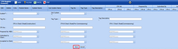
The ITR register will be saved and listed in the ITR Register (Generic) page.
7.10.2 Edit an ITR Register
If you want to edit any existing ITR register in the ITR Register (Generic) page, do the following steps,
- Click
 (Edit icon) in the Edit column for the respective ITR register. See Fig 7.10.
The ITR Register (Generic) page shows the details of the added ITR register.
-
Click any box where you want to edit the details, and then edit the details in the respective box.
-
Click Save.

7.10.3 Delete an ITR Register
If you want to delete any ITR register in the ITR Register (Generic) page, you can use  (Delete icon) provided in the ITR Register (Generic) page. To know how to delete, see the topic, “Delete P&ID”.
7.10.4 View an ITR Register Report
If you want to view the ITR register report, click  (print icon) provided in the upper side of the ITR Register (Generic) page. See Fig 7.10.
7.10.5 Filter an ITR Register
If you want to filter any ITR register in the ITR Register (Generic) page, you can use  (FILTER button) located on the ITR Register (Generic) page. To know how to filter, see the topic, “Filter P&ID”.
7.10.6 Export an ITR Register
You can export the ITR Register in the ITR Register (Generic) page in both the pdf and excel formats by using  (PDF button) and
  (Excel button). To know how to export, see the topic, “Export P&ID list”.
7.10.7 Import Multiple ITR Register
If you want to import multiple ITR register together, do the following,
- Click
 (TEMPLATE button). See Fig 7.10.
An excel worksheet will be downloaded with a predefined template to enter the details of ITR register.

- Enter the required ITR register details in the respective columns of the excel worksheet.
-
Once you have added the ITR register details in the excel worksheet, save the excel worksheet on your computer.
-
Click
 (IMPORT button). See Fig 7.10.
A new window opens for importing the excel worksheet saved on your computer.

-
Click
 (Browse button) to select the excel worksheet to be uploaded.
 -
Select the excel worksheet you want to upload from your computer.
-
Click
 (Upload button) to export the ITR register details that are included in the excel worksheet.


The details of the ITR register in the worksheet will be displayed in the ITR Register (Generic) page.
7.10 ITR Register Summary
The ITR Register Summary tab in the Test Pack menu helps you to view the ITR register summary report. To view the report,
- Click ITR Register Summary in the Test Pack menu.
The ITR Register (Generic) Summary Report page opens.
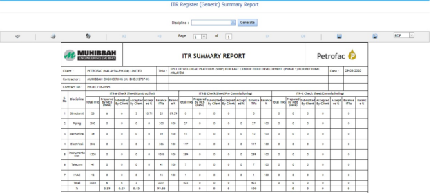
Figure 10.11: ITR Register (Generic) Summary Report page

7.11.1 Print an ITR Register Summary Report
If you want to print an ITR register summary report, use  and
and  (print icons) provided in the ITR Register (Generic) Summary Report page.
- If you want to print the current page of the ITR register summary report, click
 (print icon including the page number).
 -
If you want to print all the pages of the ITR register summary report, click
 (print icon).


7.11.2 View an ITR Register Summary Report
You can view the ITR register summary report in various formats by using the option  provided in the upper right corner of the ITR Register (Generic) Summary Report page.
7.12 Management of Change
Management of change (MOC) is a systematic approach to organizational changes with the aim of ensuring the continued safety of the workforce throughout the process. These systematic processes ensure that the change is dealt with in a proactive fashion.
The Management of Change tab in the Test Pack menu used to add the details of the management of change.
- Click Management of Change in the Test Pack menu.
The Management of Change page opens.
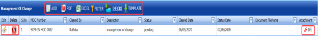
Figure 7.12: Management of Change page

7.12.1 Add the Details of Management of Change
If you want to add the details of the management of change, do the following steps,
- Click
 (Add button) in the Management of Change page.
The page shows a new window to add the details of the management of change.
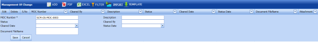
-
In the MOC Number box, enter the management of change number.
-
In the Description box, enter the description for the management of change.
-
In the Status box, enter the status of the management of change.
-
In the Cleared by box, enter the name of a person who has cleared the management of change.
-
In the Cleared Date box, select the cleared date of the management of change.
-
In the Status Date box, select the status date of the management of change.
-
In the Document File Name box, enter the document file name.
-
Click Save.
The management of change is added and listed in the Management of Change page.


7.12.2 Edit a Management of Change
If you want to edit any existing management of change in the Management of Change page, do the following steps,
- Click
 (Edit icon) in the Edit column for the respective management of change. See Fig 7.12.
The page opens with the details of the selected management of change.
-
Click any box where you want to edit the details, and then edit the details in the respective box.
-
Click Save.

7.12.3 Attach a File into a Management of Change
If you want to attach a file with any existing management of change listed in the Management of Change page, you can attach the file by using  (Attach icon) in the Attachment column. To know how to attach, follow the procedures given in the topic “Attach a file into P&ID”.
7.12.4 Export Management of Change List
You can export a list of management of change added in the Management of Change page in both the pdf and excel formats by using  (PDF button) and
  (Excel button). To know how to export, see the topic, “Export P&ID list”.
7.12.5 Filter a Management of Change
If you want to filter any specific management of change in the Management of Change page, you can use  (FILTER button) located on the Management of Change page. To know how to filter, see the topic, “Filter P&ID”.
7.12.6 Import Multiple Management of Change
If you want to import multiple management of change together, do the following,
-
Click
 (TEMPLATE button). See Fig 7.12.
An excel worksheet will be downloaded with a predefined template to enter the details of management of change.
-
Enter the required management of change details in the respective columns of the excel worksheet.
-
Once you have added the management of change details in the excel worksheet, save the excel worksheet on your computer.
-
Click
 (IMPORT button). See Fig 7.12.
A new window opens for importing the excel worksheet saved on your computer.

- Click
 (Browse button) to select the excel worksheet to be uploaded.
 -
Select the excel worksheet you want to upload from your computer.
- Click
 (Upload button) to export the management of change that are included in the excel worksheet.


The details of the management of change in the worksheet will be displayed in the Management of Change page.
7.13 Technical Queries
Technical queries are used by companies and their contractors to ask each other questions or to gather more information.
The Technical Queries tab in the Test Pack menu used to add the details of the technical query.
- Click Technical Queries in the Test Pack menu.
The Technical Queries page opens.

Figure 7.13: Technical Queries page

7.13.1 Add the Details of Technical Query
If you want to add the details of the technical query, do the following steps,
-
Click
 (Add button) in the Technical Queries page.
The page shows a new window to add the details of the technical query.
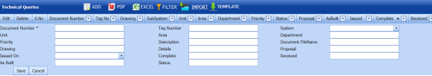
-
In the Document Number box, enter the document number.
-
In the Tag Number box, enter the tag number.
-
In the System box, select a system.
-
In the Unit box, enter the name of a unit.
-
In the Area box, enter the name of an area.
-
In the Department box, enter the department name.
-
In the Priority box, enter the priority detail.
-
In the Description box, enter the description of the technical query.
-
In the Document File Name box, enter the document file name.
-
In the Drawing box, enter the drawing number.
-
In the Issued on box, enter the issued date of technical query.
-
In the Status box, enter the status of the technical query.
-
Click Save.
The technical query is added and listed in the Technical Queries page.


7.13.2 Edit a Technical Query
If you want to edit any existing technical query in the Technical Queries page, do the following steps,
- Click
 (Edit icon) in the Edit column for the respective technical query. See Fig 7.13.
The page opens with the details of the selected technical query.
- Click any box where you want to edit the details, and then edit the details in the respective box.
-
Click Save.

7.13.3 Attach a File into a Technical Query
If you want to attach a file with any existing technical query listed in the Technical Queries page, you can attach the file by using  (Attach icon) in the Attachment column. To know how to attach, follow the procedures given in the topic “Attach a file into P&ID”.
7.13.4 Export Technical Queries List
You can export a list of technical queries added in the Technical Queries page in both the pdf and excel formats by using  (PDF button) and
  (Excel button). To know how to export, see the topic, “Export P&ID list”.
7.13.5 Filter a Technical Query
If you want to filter any specific technical query in the Technical Queries page, you can use  (FILTER button) located on the Technical Queries page. To know how to filter, see the topic, “Filter P&ID”.
7.13.6 Import Multiple Technical Queries
If you want to import multiple technical queries together, do the following,
- Click
 (TEMPLATE button). See Fig 7.13.
An excel worksheet will be downloaded with a predefined template to enter the details of technical query.
- Enter the required technical query details in the respective columns of the excel worksheet.
- Once you have added the technical query details in the excel worksheet, save the excel worksheet on your computer.
- Click
 (IMPORT button). See Fig 7.13.
A new window opens for importing the excel worksheet saved on your computer.

- Click
 (Browse button) to select the excel worksheet to be uploaded.
 -
Select the excel worksheet you want to upload from your computer.
-
Click
 (Upload button) to export the technical query that are included in the excel worksheet.


The details of the technical query in the worksheet will be displayed in the Technical Queries page.
7.14 Site Instructions
A site instruction is a formal instruction sent from the head contractor that contains directives for contractors working on a piping project.
The Site Instructions tab in the Test Pack menu used to add the details of the site instruction.
- Click Site Instructions in the Test Pack menu.
The Site Instructions page opens.
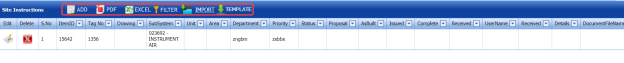

7.14.1 Add the Details of Site Instructions
If you want to add the details of the site instruction, do the following steps,
- Click
 (Add button) in the Site Instructions page.
The page shows a new window to add the details of the site instruction.
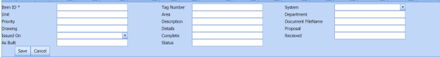
-
In the Item ID box, enter the item id number.
-
In the Tag Number box, enter the tag number.
-
In the System box, select a system.
-
In the Unit box, enter the name of a unit.
-
In the Area box, enter the name of an area.
-
In the Department box, enter the department name.
-
In the Priority box, enter the priority detail.
-
In the Description box, enter the description of the technical query.
-
In the Document File Name box, enter the document file name.
-
In the Drawing box, enter the drawing number.
-
In the Issued on box, enter the issued date of technical query.
-
In the Status box, enter the status of the technical query.
-
Click Save.
The site instruction is added and listed in the Site Instructions page.


7.14.2 Edit a Site Instruction
If you want to edit any existing site instruction in the Site Instructions page, do the following steps,
- Click
 (Edit icon) in the Edit column for the respective site instruction. See Fig 7.14.
The page opens with the details of the selected site instruction.
- Click any box where you want to edit the details, and then edit the details in the respective box.
-
Click Save.

7.14.3 Attach a File into a Site Instruction
If you want to attach a file with any existing site instruction listed in the Site Instructions page, you can attach the file by using  (Attach icon) in the Attachment column. To know how to attach, follow the procedures given in the topic “Attach a file into P&ID”.
7.14.4 Export Site Instructions List
You can export a list of site instructions added in the Site Instructions page in both the pdf and excel formats by using  (PDF button) and
  (Excel button). To know how to export, see the topic, “Export P&ID list”.
7.14.5 Filter a Site Instruction
If you want to filter any specific site instruction in the Site Instructions page, you can use  (FILTER button) located on the Site Instructions page. To know how to filter, see the topic, “Filter P&ID”.
7.14.6 Import Multiple Site Instructions
If you want to import multiple site instructions together, do the following,
- Click
 (TEMPLATE button). See Fig 7.14.
An excel worksheet will be downloaded with a predefined template to enter the details of site instruction.
- Enter the required site instruction details in the respective columns of the excel worksheet.
- Once you have added the site instruction details in the excel worksheet, save the excel worksheet on your computer.
- Click
 (IMPORT button). See Fig 7.14.
A new window opens for importing the excel worksheet saved on your computer.

- Click
 (Browse button) to select the excel worksheet to be uploaded.
 -
Select the excel worksheet you want to upload from your computer.
-
Click
 (Upload button) to export the site instruction that are included in the excel worksheet.


The details of the site instruction in the worksheet will be displayed in the Site Instructions page.
7.15 Test Pack Status Report
Test Pack Status Report shows the status of test pack.
If you want to view a test pack status report, do the following steps,
- Click Test Pack Status Report in the Piping menu.
The Test Pack Status Report page opens.

Figure 7.15: Test Pack Status Report page
- In the ISO/Drawing Number box, select the ISO/drawing from a drop-down list.
- In the Spool Number box, select the spool number from a drop-down list.
-
Click Go.
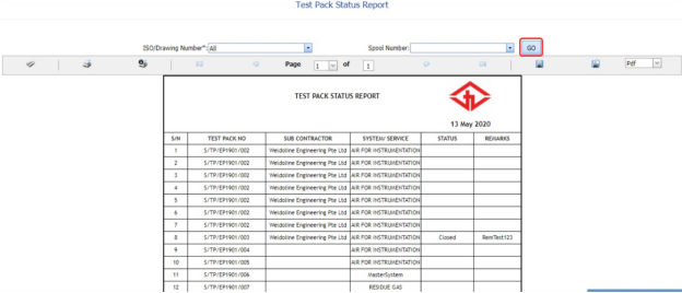
The Test Pack Status Report page shows the test pack number, subcontractor name, system/service information, and test pack status.
7.15.1 Print a Test Pack Status Report
If you want to print the test pack status report, use  and
and  (print icons) provided in the Test Pack Status Report page. See Fig 7.15.
- If you want to print the current page of the test pack status report, click
 (print icon including the page number).
 -
If you want to print all the pages of the test pack status report, click
 (print icon).


7.15.2 Export a Test Pack Status Report
You can export the test pack status report in various formats by using the option provided in the upper right corner of the Test Pack Status Report page.
No Comments