
Inspection
5.0 Inspection
5.1 RFI Fit Up Request Generic
If you want to add an RFI fit up request generic, do the following,
- Click
 (ADD button) in the RFI Fit up Request Generic page.
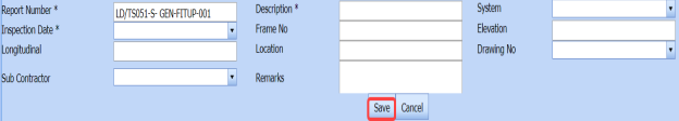
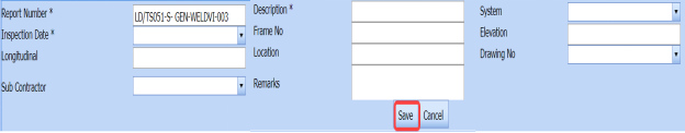
A new window opens to add an RFI fit up request generic.

 Tip: A report number for a new RFI fit up request generic will be updated automatically in the Report Number box.
 -
In the Description box, enter the description for the RFI fit up request generic.
-
In the System box, select a system from a drop-down list.
-
In the Inspection Date box, choose the date of inspection.
-
In the Frame No box, enter the frame number.
-
In the Elevation box, enter the elevation value.
-
In the Longitudinal box, enter the longitudinal value.
-
In the Location box, enter the location where the inspection to be done.
-
In the Drawing No box, select the drawing number from a drop-down list.
-
In the Sub Contractor box, select the sub-contractor from a drop-down list.
-
In the Remarks box, enter your remarks if any.
-
Click Save.


The RFI fit up request generic is inserted successfully. Once you have added the RFI fit up request generic, you must add the RFI data for the added request.
5.1.2 Add RFI Data for an Added RFI Fit Up Request Generic
If you want to add RFI data for the added RFI fit up request generic, do the following,
- Click
 (Edit icon) in the RFI Data column of the RFI Fit up Request Generic See Fig 5.1.
The RFI Inspection Request List window opens.

- In the Inspection From box, enter the detail from where the inspection should start.
-
In the Inspection To box, enter the detail to where the inspection should end.
- In the Inspection Details option, select 1stInspection, 2nd Inspection or 3rd Inspection according to the inspection details.
-
In the Others box, enter any other inspection related details.
-
In the Refer to Report No box, enter the report number for reference.
-
In the RFI Date box, choose the RFI date.
-
In the Inspection Result option, if the inspection result is accepted, select Accepted otherwise select Rejected.
-
In the Remarks box, enter your remarks if any.
-
In the Inspected by box, enter the name of a person who has done inspection.
-
In the Inspected Date box, choose the date of inspection.
-
In the Witnessed By box, enter the name of the witnessed person.
-
In the Witnessed Date box, choose the date of witnessed.
-
In the PCML Rep Name box, enter the representative name of PCML.
-
In the PCML Rep Date box, choose the PCML rep date.
-
In the MEB Rep Name box, enter the representative name of MEB.
-
In the MEB Rep Date box, choose MEB rep date.
-
Click Save.
The RFI data is successfully added.


5.1.3 Clone an RFI Fit Up Request Generic
The Clone option in the RFI Fit up Request Generic page used to create a RFI weld VI generic request in the RFI Weld VI Generic page, as a copy of RFI fit up request generic, See Fig 5.4.
If you click  (Clone icon) in the Clone column of the RFI Fit up Request Generic page, an RFI weld VI generic request is added in the RFI weld VI generic page.
 Tip: You can create multiple copies of RFI weld VI generic request for a single RFI fit up request generic.
5.1.4 Print an RFI Report
If you want to print an RFI report, click  (print icon) provided in the RFI Report column of the RFI Fit up Request Generic page. See Fig 5.1.
5.1.5 Submit an RFI Fit Up Request Generic
Once you have added the RFI fit up request generic, the Submission column in the RFI Fit up Request Generic page is appeared with  (Submit and Reject icons).
- If you want to submit the RFI fit up request generic, click
 (Submit icon) in the Submission column. Otherwise click
 (Reject icon) to reject the request.


5.1.6 Print an RFI Fit Up Request Generic Report
If you want to print an RFI fit up request generic report, click (print icon) provided in the Report column of the RFI Fit up Request Generic page. See Fig 5.1.
5.1.7 Attach a File into an RFI Fit Up Request Generic
If you want to attach any file with any RFI fit up request generic added in the RFI Fit up Request Generic page, follow the procedures given in the topic “Attach a file into a client master drawing” in the Client Master Drawing section.
5.1.8 View Signature Details of QA User, Surveyor, and Client
Once the RFI fit up inspection has completed, the QA, surveyor, and client add their signature based on their corresponding roles. You can view their signature by using  (Sign icon) in the Sign Details column in the RFI Fit up Request Generic page.
5.1.9 Edit Any RFI Fit Up Request Generic
If you want to edit any existing RFI fit up request generic in the RFI Fit up Request Generic page, do the following,
- Click
 (Edit icon) in the Edit column for the respective RFI fit up request generic. See Fig 5.1.
A new window opens to edit the RFI fit up request generic.
-
Click any box where you want to edit the details, and then edit the details in the respective box.
-
Click Save.

5.1.10 Export RFI Fit Up Request Generic List
You can export a list of RFI fit up request generic added in the RFI Fit up Request Generic page in the pdf and excel formats. To know how to export, see the topic, “Export Areas list” in the Area option.
5.1.11 Filter Any RFI Fit Up Request Generic
If you want to filter any RFI fit up request generic from the list of RFI fit up request generic in the RFI Fit up Request Generic page, you can use the (FILTER button). To know how to filter, see the topic, ”Filter Any Area”.
5.2 RFI Fit up Request (Heat Numbers)
The RFI Fit up Request tab allows you add an RFI fit up request to check the fit-up quality of pipes and joints used in the Structural project by a sub-contractor. To navigate to the RFI fit up request adding page,
- Click RFI Fit up Request in the Inspection menu.
The RFI Fit up Inspection Request page opens.
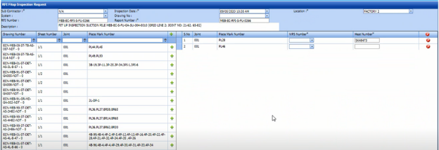
Figure 4.2: RFI Fit up Inspection Request page

5.2.1 Add an RFI Fit Up Request
If you want to add an RFI fit up request, do the following steps,
- In the Sub Contractor box, select a sub-contractor from a drop-down list.
-
In the Inspection Date box, select the inspection date.
 Note: The inspection date should be as current date or upcoming dates. The system will not accept if you have given the previous dates.
 -
In the Location box, select a location from a drop-down list.
-
In the System box, select a system from a drop-down list.
-
In the Drawing No box, select a drawing number.
- In the Description box, enter the description for the RFI fit up request.
Before saving the added fit up request, you must add joints for the fit-up request.
-
Click
 (Add icon) of the respective joints you want to add.
The added joints will be moved and listed in the right side of the page.

-
In the Heat No 1 box, enter the heat number of the first component if you know.
-
In the Heat No 2 box, enter the heat number of the second component if you know.
 Tip: If you want to remove any added joint, click
 (Remove icon) of the respective joint.
 -
Click Save.


The RFI fit up request is successfully added. If you want to view the added request, navigate to t the View RFI Fit up page.
5.3 View RFI Fit up (Heat Numbers)
The View RFI Fit up tab helps you to view and edit the RFI fit up requests, which are added by using the RFI Fit up Request tab. This tab also allows you to add a new RFI fit up request.
- Click View RFI Fit up in the Inspection menu.
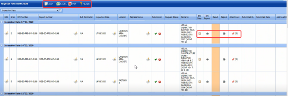
The Request for Inspection page opens with a list of added RFI fit up requests.
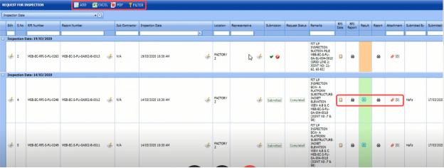
Figure 5.3: Request for Inspection page

5.3.1 Add an RFI Fit Up Request
If you want to add an RFI fit up request, do the following,
-
Click
 (ADD button) in the RFI Fit up Request List page.
The system redirects you into RFI Fit up Inspection Request page. To know how to add an RFI fit up request, See the topic, “Add an RFI Fit up Request”.

Once you have added the RFI fit up request, you must submit the added request for inspection.
5.3.2 Add Representative for Added RFI Fit Up Request
If you want to add a representative for any added RFI fit up request,
- Click
 (Edit icon) in the Representative column for the respective RFI fit up request.
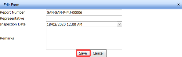
The Edit Form window opens.

-
In the Representative box, enter the name of a representative.
-
In the Inspection Date box, select the date of inspection.
-
In the Remarks box, enter your remarks if any.
-
Click Save.


5.3.3 Edit Any RFI Fit Up Request
If you want to edit any existing RFI fit up request in the Request for Inspection page, do the following,
- Click
 (Edit icon) in the Edit column for the respective RFI fit up request. See Fig 5.3.
The RFI Fit up Inspection Request page opens with the details of the selected RFI fit up request.
- Click any box where you want to edit the details, and then edit the details in the respective box.
-
Click Save.

5.3.4 Submit and Approve an RFI Fit Up Request
Once you have added the RFI fit up request, the Submission column in the RFI Fit up Request Lists page is appeared with  (Submit and Reject icons). See Fig 5.3.
- If you want to submit the RFI fit up request, click
 (Submit icon) in the Submission Otherwise click
  (Reject icon) to reject the request.
Once you have submitted the RFI fit up request, the Request Status column in the RFI Fit up Requests List page is appeared with
 (Approve and Reject icons).
 - If you want to approve the RFI fit up request, click
 (Submit icon) in the Request Status Otherwise click
 (Reject icon) to reject the request.
The approved request will be moved to for inspection.


5.3.5 Add Results of RFI Fit Up Inspection
After completing the RFI fit up inspection for the added request, you can add the inspection result details. To add results, do the following steps,
- Click
 (Add icon) in the Results column of the respective request.
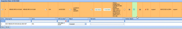
The RFI Fit up Request List window opens with a list of joints.
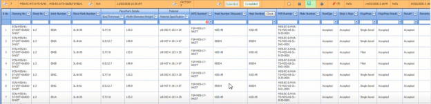
- If you want to update the heat numbers and piece mark details, click on the respective box and update.
-
If you want to update the WPS number in the WPS Number column, you can change the WPS number from a drop-down list.
- Update the result for root gap by selecting Accepted or Rejected in the Root Gap column based on the inspection.
- Update the result for straight/ alignment by selecting Accepted or Rejected in the Strgt/Align column based on the inspection.
-
In the Edge Prep column, select the type of the edge preparation from a drop-down list.
-
In the Result column, update the RFI fit up inspection result by selecting Pending, Accepted, Rejected, or Cancelled.
-
In the Remarks column, enter you remarks if any.


5.3.6 View an RFI Fit Up Report
If you want to view an RFI fit up report, click  (print icon) provided in the Report column of the Request for Inspection page. See Fig 5.3.
5.3.7 View Signature Details of Inspectors
You can view the sign details of the inspectors such as QA, Sub contractor, Client, and Owner, once they completed the RFI fit up inspection and submitted the inspection result details including their signature. To view the signature details, click  (Sign icon) in the Sign Details column in the Request for Inspection page.
5.3.8 Attach a File into an RFI Fit up Request
If you want to attach a file with any existing RFI fit up request listed in the RFI Fit up Requests List page, you can attach the file by using (Attach icon) in the Attachment column. To know how to attach, follow the procedures given in the topic “Attach a file into a client master drawing”.
5.3.9 Export RFI Fit up Request List
You can export a list of RFI fit up requests added in the RFI Fit up Requests List page in both the pdf and excel formats by using  (PDF button) and
  (Excel button). To know how to export, see the topic, “Export Areas list”.
5.3.10 Filter RFI Fit up Request
If you want to filter any specific RFI fit up request in the RFI Fit up Requests List page,
- you can use the filter box
 provided in the upper side of the RFI Fit up Requests List To filter the any specific RFI fit up request, select the Drawing Number and Date in the boxes and click Search.
 - you can use
 (FILTER button) located on the RFI Fit up Requests List page. To know how to filter, see the topic, ”Filter Any Area”.


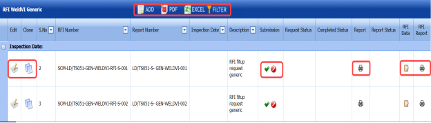
5.4 RFI Weld VI Generic
Once the RFI fit up inspection process has completed, the materials are moved for weld inspection process. The RFI Weld VI Generic tab in the Inspection menu helps you to add an RFI weld VI generic.
- Click the RFI Weld VI Generic tab in the Inspection menu.
The RFI Weld VI Generic page opens.
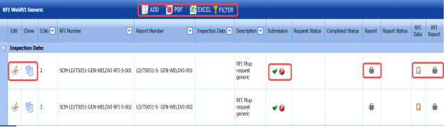
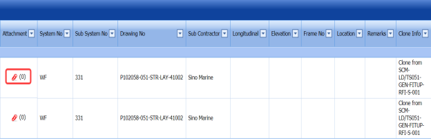

Figure 5.4: RFI Weld VI Generic page

5.4.1 Add an RFI Weld VI Generic
If you want to add an RFI weld VI generic, do the following,
- Click
 (ADD button) in the RFI Weld VI Generic page.
A new window opens to add an RFI weld VI generic.
 Note: The fields notified with a symbol (*) are mandatory. You must enter the relevant details in that fields before saving.
 Tip: A report number for a new RFI weld VI generic will be updated automatically in the Report Number box.
 - In the Description box, enter the description for the RFI weld VI generic.
-
In the System box, select a system from a drop-down list.
-
In the Inspection Date box, choose the date of inspection.
-
In the Frame No box, enter the frame number.
-
In the Elevation box, enter the elevation value.
-
In the Longitudinal box, enter the longitudinal value.
-
In the Location box, enter the location where the inspection to be done.
-
In the Drawing No box, select the drawing number from a drop-down list.
-
In the Sub Contractor box, select the sub-contractor from a drop-down list.
-
In the Remarks box, enter your remarks if any.
-
Click Save.


The RFI weld VI generic is added successfully. Once you have added the RFI weld VI generic, you must add the RFI data for the added request.
5.4.2 Add RFI Data for the Added RFI Weld VI Generic
If you want to add RFI data for the added RFI weld VI generic, do the following,
- Click
 (Edit icon) in the RFI Data column of the RFI Weld VI Generic See Fig 5.4.
The RFI Inspection Request List window opens.

-
In the Inspection From box, enter the detail from where the inspection should start.
-
In the Inspection To box, enter the detail to where the inspection should end.
-
In the Inspection Details option, select 1st Inspection, 2nd Inspection or 3rd Inspection according to the inspection details.
-
In the Others box, enter any other inspection related details.
-
In the Refer to Report No box, enter the report number for reference.
-
In the RFI Date box, choose the RFI date.
- In the Inspection Result option, if the inspection result is accepted, select Accepted otherwise select Rejected.
-
In the Remarks box, enter your remarks if any.
-
In the Inspected by box, enter the name of a person who has done inspection.
-
In the Inspected Date box, choose the date of inspection.
-
In the Witnessed By box, enter the name of the witnessed person.
-
In the PCML Rep Name box, enter the representative name of PCML.
-
In the PCML Rep Date box, choose the PCML rep date.
-
In the MEB Rep Name box, enter the representative name of MEB.
-
In the MEB Rep Date box, choose MEB rep date.
-
Click Save.


The RFI data is successfully added.
5.4.3 Clone an RFI Weld VI Generic
The Clone option in the RFI Weld VI Generic page used to create a vacuum test request, an air test request, a hydrostatic test request, and an NDT request, as a copy of RFI weld VI generic request.
- Click
 (Clone icon) in the Clone column of the RFI Weld VI Generic page.
The Clone box opens.
-
Select any test from the given list.
-
Click
 (Add button).
A new request for the selected test will be added in the respective pages.


5.4.4 Print an RFI Report
If you want to print an RFI report, click  (print icon) provided in the RFI Report column of the RFI Weld VI Generic page. See Fig 5.4.
5.4.5 Submit an RFI Weld VI Generic
Once you have added the RFI weld VI generic, the Submission column in the RFI Weld VI Generic page is appeared with  (Submit and Reject icons).
- If you want to submit the RFI weld VI generic, click
 (Submit icon) in the Submission column. Otherwise click
 (Reject icon) to reject the request.


5.4.6 Print an RFI Weld VI Generic Report
If you want to print an RFI weld VI generic report, click  (print icon) provided in the Report column of the RFI Weld VI Generic page. See Fig 5.4.
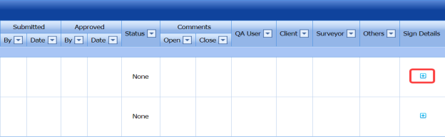
5.4.7 View Signature Details of QA User, Surveyor, and Client
Once the weld VI inspection has completed, the QA, surveyor, and client add their signature based on their corresponding roles. You can view their signature by using (Sign icon) in the Sign Details column in the RFI Weld VI Generic page.
5.4.8 Attach a File into an RFI Weld VI Generic
If you want to attach any file with any RFI weld VI generic added in the RFI Weld VI Generic page, follow the procedures given in the topic “Attach a file into a client master drawing” in the Client Master Drawing section.
5.4.9 Edit Any RFI Weld VI Generic
If you want to edit any existing RFI weld VI generic in the RFI Weld VI Generic page, do the following,
- Click
 (Edit icon) in the Edit column for the respective RFI weld VI generic. See Fig 5.4.
A new window opens to edit the RFI weld VI generic.
- Click any box where you want to edit the details, and then edit the details in the respective box.
-
Click Save.

5.4.10 Export RFI Weld VI Generic List
You can export a list of RFI weld VI generic added in the RFI Weld VI Generic page in the pdf and excel formats. To know how to export, see the topic, “Export Areas list” in the Area option.
5.4.11 Filter Any RFI Weld VI Generic
If you want to filter any RFI weld VI generic from the list of RFI weld VI generic in the RFI Weld VI Generic page, you can use the  (FILTER button). To know how to filter, see the topic, ”Filter Any Area”.
5.5 RFI Weld VI Request (Heat Numbers)
The RFI Weld VI Request tab in the Inspection menu allows you to add an RFI weld VI request to perform visual inspection of welded pipes and joints used in the Structural project. To navigate to the RFI weld VI request adding page,
- Click RFI Weld VI Request in the Inspection menu.
The RFI Weld Visual Request page opens.
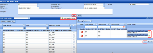
Figure 5.5: RFI Weld Visual Request page

5.5.1 Add an RFI Weld VI Request
If you want to add an RFI weld VI request, do the following steps,
- In the Sub Contractor box, select the name of a sub-contractor from a drop-down list.
-
In the Inspection Date box, select the inspection date.
 Note: The inspection date should be as current date or upcoming dates. The system will not accept if you have given the previous dates.
 -
In the Location box, select a location from a drop-down list.
-
In the System box, select a system from a drop-down list.
-
In the Drawing No box, select the drawing number from a drop-down list.
-
In the Description box, enter the description for the request.
Before saving the added weld VI request, you must add joints for the weld VI request.
 Note: You can add multiple joints for one request.
The RFI Weld Visual Request page shows a list of joints including the corresponding sheet and piece mark numbers. If you want to add joints for the RFI weld VI request, do the following steps,

- Select the checkbox of the respective joints you want to add.
The added joints will be moved and listed in the right side of the page.

- Update the welder details by using (Add icon) provided in the Welder Details column.
-
-
Click (Add icon) of the respective joint number.
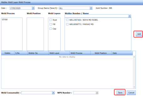
The Welder- Weld Layer- Weld Process window opens.

-
In the Date box, select the date.
-
In the Group Name box, select the group name from a drop-down list.
-
In the Weld Process field, select a weld process.
-
In the Weld Position field, select the welding position.
-
In the Weld Layers field, select the weld layers you want add.
-
In the Welder Number/ Name field, select the welders you want to add.
-
Click Add.
The selected welders will be added and listed in the below table. See the above figure.
-
In the Weld Consumable box, select the weld consumable from a drop-down list.
-
In the WPS Number box, select the WPS number from a drop-down list.
-
Click Save.
 Tip: If you want to remove any added joint, click (Remove icon) of the respective joint.
-
-
- Click Save.


The RFI weld VI request is successfully added. If you want to view the added request, navigate to View RFI Weld VI.
5.6 View RFI Weld VI (Heat Numbers)
The View RFI Weld VI tab helps you to view and edit the RFI weld VI request, which is added by using the RFI Weld VI Request tab. This tab also allows you to add a new RFI weld VI request.
- Click View RFI Weld VI in the Inspection menu.
The Request for Inspection page opens with a list of added RFI weld VI requests.

Figure 5.6: Request for Inspection page
5.6.1 Add an RFI Weld VI Request
If you want to add an RFI weld VI request, do the following,
- Click
 (ADD button) in the Request for Inspection page.
The system redirects you into Request for Inspection page. To know how to add an RFI weld VI request, See the topic, “Add an RFI Weld VI Request”.

Once you have added the RFI weld VI request, you must submit the added request for weld visual inspection.
5.6.2 Add Representative for Added RFI Weld VI Request
If you want to add a representative for any added RFI weld VI request,
- Click
 (Edit icon) in the Representative column for the respective RFI weld VI request.
The Edit Form window opens.
-
In the Representative box, enter the name of a representative.
-
In the Inspection Date box, select the date of inspection.
-
In the Remarks box, enter your remarks if any.
-
Click Save.


5.6.3 Edit Any RFI Weld VI Request
If you want to edit any existing RFI weld VI request in the Request for Inspection page, do the following,
- Click
 (Edit icon) in the Edit column for the respective RFI weld VI request. See Fig 5.6.
The Request for Inspection page opens with the details of the selected RFI weld VI request.
- Click any box where you want to edit the details, and then edit the details in the respective box.
-
Click Save.

5.6.4 Submit and Approve an RFI Weld VI Request
Once you have added the RFI weld VI request, the Submission column in the Requests for Inspection page is appeared with  (Submit and Reject icons). See Fig 5.6.
-
If you want to submit the RFI weld VI request, click
 (Submit icon) in the Submission column. Otherwise click
  (Reject icon) to reject the request.
Once you have submitted the RFI weld VI request, the Request Status column in the Request for Inspection page is appeared with
 (Approve and Reject icons).
 - If you want to approve the RFI weld VI request, click
 (Submit icon) in the Request Status Otherwise click
  (Reject icon) to reject the request.


The approved request will be moved to for inspection.
5.6.5 Add Results of RFI weld Visual Inspection
After completing the RFI weld visual inspection for the added request, you can add the inspection result details. To add results, do the following steps,
- Click
 (Add icon) in the Results column of the respective request.
The Request for Inspection window opens with a list of joints added for the particular request.

- In the Result column, select the result for each joint from the given result options in the drop-down list.
-
In the Remarks box, enter your remarks if any.
-
Click Save.

5.6.6 View an RFI Weld VI Report
If you want to view an RFI weld VI report, click  (print icon) provided in the Report column of the RFI Weld Visual Requests List page. See Fig 5.6.
5.6.7 View Signature Details of Inspectors
You can view the sign details of the inspectors such as QA, Sub contractor, Client, and Owner, once they completed the RFI weld visual inspection and submitted the inspection result details including their signature. To view the signature details, click (Sign icon) in the Sign Details column in the RFI Weld Visual Requests List page.
5.6.8 Attach a File into an RFI Weld VI Request
If you want to attach a file with any existing RFI weld VI request listed in the RFI Weld Visual Requests List page, you can attach the file by using  (Attach icon) in the Attachment column. To know how to attach, follow the procedures given in the topic “Attach a file into a client master drawing”.
5.6.9 Export RFI Weld VI Request List
You can export a list of RFI weld VI requests added in the RFI Weld Visual Requests List page in both the pdf and excel formats by using  (PDF button) and
  (Excel button). To know how to export, see the topic, “Export Areas list”.
5.6.10 Filter RFI Weld VI Request
If you want to filter any specific RFI weld VI request in the RFI Weld Visual Requests List page,
- you can use the filter box
 provided in the upper side of the RFI Weld Visual Requests List To filter the any specific RFI weld VI request, select the Drawing Number and Date in the boxes and click Search.
 - you can use
 (FILTER button) located on the RFI Weld Visual Requests List page. To know how to filter, see the topic ”Filter Any Area”.


5.7 NDT Inspection Generic
NDT inspection used to find out welding defects of the materials. Once the fit up and welding process of the materials has completed, the materials will be moved for the NDT inspection. The currently following NDT inspection methods are RT, UT, MT, PT, Ultrasonic Thickness Gaging (UTG), Magnetic Particle Inspection (MPI) after load test, UT/MT, and PT after load test.
The NDT Inspection Generic tab in the Inspection menu helps you to add an NDT inspection generic. If you want to navigate the NDT inspection generic,
- Click the NDT Inspection Generic in the Inspection menu.
The NDT Inspection Generic page opens.
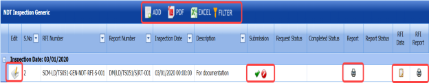


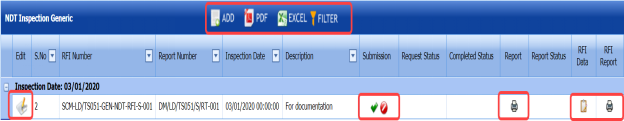
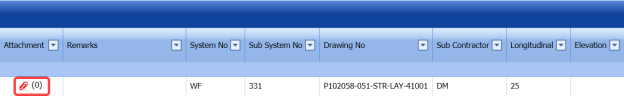
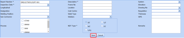
Figure 5.7: NDT Inspection Generic page
5.7.1 Add an NDT Inspection Generic
If you want to add an NDT inspection generic, do the following,
- Click
 (ADD button) in the NDT Inspection Generic page.
A new window opens to add an NDT Inspection generic.

 Note: The fields notified with a symbol (*) are mandatory. You must enter the relevant details in that fields before saving.
 Tip: A report number for a new NDT inspection generic will be updated automatically in the Report Number box.
 -
In the Description box, enter the description for the RFI weld VI generic.
-
In the System box, select a system from a drop-down list.
-
In the Inspection Date box, choose the date of inspection.
-
In the Frame No box, enter the frame number.
-
In the Elevation box, enter the elevation value.
-
In the Longitudinal box, enter the longitudinal value.
-
In the Location box, enter the location where the inspection to be done.
-
In the Drawing No box, select the drawing number from a drop-down list.
-
In the Designation box, enter the designation detail.
-
In the Cost Centre box, enter the cost centre detail.
-
In the Requisition box, select the type of request from a drop-down list.
-
In the Welding Position box, enter the position of welding.
-
In the Weld Type box, enter the type of welding.
-
In the Thickness box, enter the thickness of the welding.
-
In the Sub Contractor box, select the sub-contractor from a drop-down list.
-
In the Welder box, select the name of a welder from a drop-down list.
-
In the WPS box, enter the WPS detail.
-
In the Process box, select the welding process to be done from a specified category.
-
In the NDT Type box, select the type of NDT to be done from a specified category.
-
In the Remarks box, enter your remarks if any.
-
Click Save.


The NDT inspection generic is added successfully. Once you have added the NDT inspection generic, you must add the RFI data for the added NDT inspection generic.
5.7.2 Add RFI Data for the Added NDT Inspection Generic
If you want to add RFI data for the added NDT inspection generic, do the following,
- Click
 (Edit icon) in the RFI Data column of the NDT Inspection Generic See Fig 5.7.
The RFI Inspection Request List window opens.

- In the Inspection From box, enter the detail from where the inspection should start.
-
In the Inspection To box, enter the detail to where the inspection should end.
-
In the Inspection Details option, select 1st Inspection, 2nd Inspection or 3rd Inspection according to the inspection details.
-
In the Others box, enter any other inspection related details.
-
In the Refer to Report No box, enter the report number for reference.
-
In the RFI Date box, choose the RFI date.
-
In the Inspection Result option, if the inspection result is accepted, select Accepted otherwise select Rejected.
-
In the Remarks box, enter your remarks if any.
-
In the Inspected by box, enter the name of a person who has done inspection.
-
In the Inspected Date box, choose the date of inspection.
-
In the Witnessed By box, enter the name of the witnessed person.
-
In the Witnessed Date box, choose the date of witnessed.
-
In the PCML Rep Name box, enter the representative name of PCML.
-
In the PCML Rep Date box, choose the PCML rep date.
-
In the MEB Rep Name box, enter the representative name of MEB.
-
In the MEB Rep Date box, choose MEB rep date.
-
Click Save.


The RFI data is successfully added.
5.7.3 Print an RFI Report
If you want to print an RFI report, click (print icon) provided in the RFI Report column of the NDT Inspection Generic page. See Fig 5.7.
5.7.4 Submit an NDT Inspection Generic
Once you have added the NDT inspection generic, the Submission column in the NDT Inspection Generic page is appeared with  (Submit and Reject icons).
If you want to submit the added NDT inspection generic, click (Submit icon) in the Submission column. Otherwise click
  (Reject icon) to reject the request.
5.7.5 Print an NDT Inspection Generic Report
If you want to print an NDT inspection generic report, click (print icon) provided in the Report column of the NDT Inspection Generic page. See Fig 5.7.
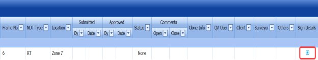
5.7.6 View Signature Details of QA User, Surveyor, and Client
Once the NDT inspection has completed, the QA, surveyor, and client add their signature based on their corresponding roles. You can view their signature by using  (Sign icon) in the Sign Details column in the NDT Inspection Generic page.
5.7.7 Attach a File into an NDT Inspection Generic
If you want to attach any file with any NDT inspection generic added in the NDT Inspection Generic page, follow the procedures given in the topic “Attach a file into a client master drawing” in the Client Master Drawing section.
5.7.8 Edit Any NDT Inspection Generic
If you want to edit any existing NDT inspection generic in the NDT Inspection Generic page, do the following,
- Click
 (Edit icon) in the Edit column for the respective NDT inspection generic. See Fig 5.7.
A new window opens to edit the NDT inspection generic.
- Click any box where you want to edit the details, and then edit the details in the respective box.
-
Click Save.

5.7.9 Export NDT Inspection Generic List
You can export a list of NDT inspection generic added in the NDT Inspection Generic page in the pdf and excel formats. To know how to export, see the topic, “Export Areas list” in the Area option.
5.7.10 Filter Any NDT Inspection Generic
If you want to filter any NDT inspection generic from the list of NDT inspection generic in the NDT Inspection Generic page, you can use the  (FILTER button). To know how to filter, see the topic, ”Filter Any Area”.
5.8 NDT Inspection Request
The NDT Inspection Request tab in the Inspection menu helps you to add an NDT inspection request to perform the NDT inspection.
5.8.1 Add an NDT Inspection Request
If you want to add an NDT inspection request, do the following
- Click the NDT Inspection Request tab in the Inspection menu.
A new page opens to add an NDT inspection request.
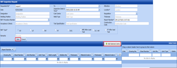
Figure 5.8: NDT Inspection Request page
 Tip: A report number and the request adding date for a new NDT inspection request will be updated automatically in the Report Number and the Date boxes, respectively.
 Note: The fields notified with a symbol (*) are mandatory. You must enter the relevant details in that fields before saving.
 - In the Requested By box, enter the name of person who has requested for the inspection.
-
In the To box, select the name of a sub-contractor from a drop-down list.
-
In the Attention box, enter any note if you want for attention.
-
In the Inspection Date & Time box, select the date of inspection.
-
In the Location box, enter the location where the inspection to be done.
-
In the Designation box, enter the designation detail.
-
In the Cost Centre box, enter the cost centre detail.
-
In the Requisition box, select the type of request from a drop-down list.
-
In the Welding Position box, enter the position of welding.
-
In the Weld Type box, enter the type of welding.
-
In the Thickness box, enter the thickness of the welding.
-
In the NDT Procedure Number, select the NDT procedure number from a drop-down list.
-
In the Acceptance Criteria box, enter the detail of acceptance criteria.
-
In the Test Specification box, enter the test specification detail.
-
In the Construction Code box, enter the construction code.
-
In the NDT Type box, select any type of NDT you want to add.
-
In the Remarks box, enter your remarks if any.
 Note: Before saving the added NDT request, you must add the details of joints. You can add multiple joints for any added NDT inspection request by using a box provided in the left side of the page. To know how to add joints, see the topic “Add joints for an NDT inspection request”.
 -
Click Save.


5.8.2 Add Joints for an NDT Inspection Request
If you want to add joints for any added NDT inspection request, do the following,
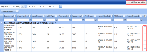
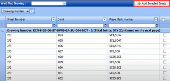
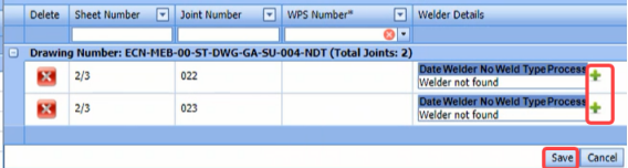
-
Click the check box of the respective joints.
-
Click
 (Add Selected Joints button).
The selected joints are moved into the Added Joints box located in the right side of the page.
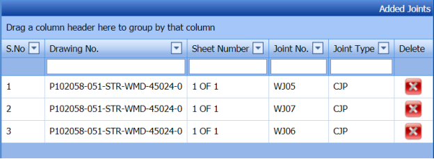


The selected joints are successfully added for the NDT inspection request.
5.9 View NDT Request
The View NDT Request tab helps you to view and edit the added NDT inspection request, which is added by using the NDT Inspection Request tab.
- Click the View NDT Request tab in the Inspection menu.
The View NDT Inspection List page opens with a list of added NDT inspection requests.
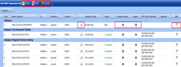
Figure 5.9: View NDT Inspection List page
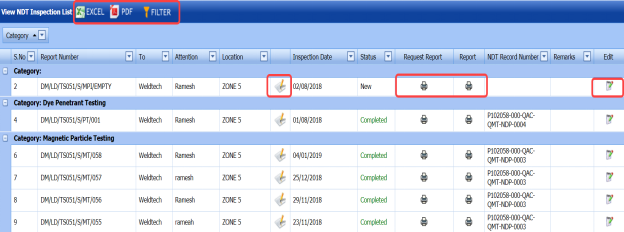
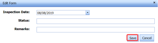
5.9.1 Change the Inspection Date for Any Added NDT Inspection Request
If you want to change the inspection date of any added NDT inspection request,
- Click
 (Edit icon) in the Inspection Date column for the respective NDT inspection request, See Fig 5.9.
The Edit Form window opens.

-
-
In the Inspection Date box, select the date of inspection.
-
Click Save.
-
-

5.9.2 Print an NDT Inspection Request Report
If you want to print an NDT inspection request report, click (print icon) provided in the Report column of the View NDT Inspection List page. See Fig 5.9.
5.9.3 Edit Any NDT Inspection Request
If you want to edit any existing NDT Inspection request in the View NDT Inspection List page, do the following,
- Click
 (Edit icon) in the Edit column for the respective NDT inspection request. See Fig 5.9.
The NDT Inspection Request page opens to edit the NDT Inspection request.
- Click any box where you want to edit the details, and then edit the details in the respective box.
-
Click Save.

5.9.4 Export NDT Inspection Request List
You can export a list of NDT inspection request added in the View NDT Inspection List page in the pdf and excel formats. To know how to export, see the topic, “Export Areas list” in the Area option.
5.9.5 Filter Any NDT Inspection Request
If you want to filter any NDT inspection request from the list of NDT inspection requests in the View NDT Inspection List page, you can use the  (FILTER button). To know how to filter, see the topic, ”Filter Any Area”.
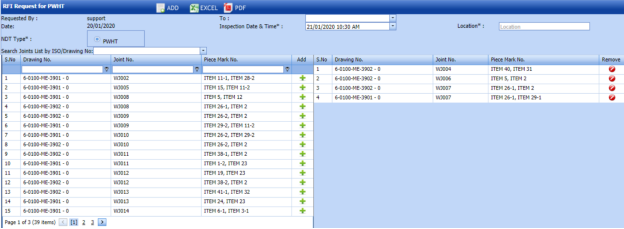
5.10 RFI Request for Post Weld Heat Treatment (PWHT)
PWHT is defined as a heat treatment after welding performed to strengthen the weld metal and heat affected zone. Thus, decreasing hardness and improving toughness, and decreasing the residual stresses associated with welding.
The RFI Request for PWHT tab in the Inspection menu used to add an RFI request for PWHT.
- Click the RFI Request for PWHT tab in the Inspection menu.
The RFI Request for PWHT page opens.

Figure 5.10: RFI Request for PWHT page
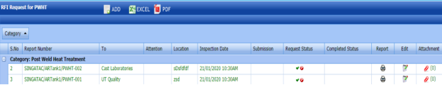
5.10.1 Add an RFI Request for PWHT
If you want to add an RFI request for PWHT, do the following,
- Click
 (ADD button) in the RFI Request for PWHT page. See Fig 5.10.
A new window opens to add an RFI request for PWHT.

 Note: The fields notified with a symbol (*) are mandatory. You must enter the relevant details in that fields before saving.
 - Note: The fields notified with a symbol (*) are mandatory. You must enter the relevant details in that fields before saving.
-
In the Location box, enter a location where the inspection to be done.
-
In the Inspection Date box, select the date of inspection.
-
In the NDT Type box, select PWHT.
- In the Search Joints List by ISO/ Drawing No box, select a drawing number from a drop-down list.
The Joint numbers and the piece mark numbers will be listed for the selected drawing number.
- If you want to add joints, click
 (Add icon) of the respective joint number.
The added joints will be moved into the left side window of the RFI Request for PWHT page.
-
Click Save AFI Request.
The RFI request for PWHT is successfully added.


5.10.2 Submit and Approve an RFI Request for PWHT
Once you have added the RFI request for PWHT, the Request Status column in the RFI Request for PWHT page is appeared with (Submit and Reject icons).
- If you want to submit the RFI request for PWHT, click
 (Submit icon) in the Request Status column. Otherwise click
 (Reject icon) to reject the request.
Once you have submitted the RFI request for PWHT, the Completed Status column in the RFI Request for PWHT page is appeared with
 (Accept and Reject icons).
 - If you want to approve the RFI request for PWHT, click
 (Submit icon) in the Completed Status Otherwise click
 (Reject icon) to reject the request.


5.10.3 Attach a File into an RFI Request for PWHT
If you want to attach any file with any RFI request for PWHT listed in the RFI Request for PWHT page, follow the procedures given in the topic “Attach a file into a client master drawing” in the Client Master Drawing section.
5.10.4 Print an RFI Request for PWHT Report
If you want to print an RFI request for PWHT report, click  (print icon) provided in the Report column of the RFI Request for PWHT page. See Fig 5.12.
5.10.5 Edit Any RFI Request for PWHT
If you want to edit any existing RFI request for PWHT in the RFI Request for PWHT page, do the following,
- Click
 (Edit icon) in the Edit column for the respective RFI request for PWHT. See Fig 5.10.
A new window opens to edit the RFI request for PWHT.
- Click any box where you want to edit the details, and then edit the details in the respective box.
-
Click Save AFI Request.

5.10.6 Export RFI Request for PWHT
You can export a list of RFI request for PWHT added in the RFI Request for PWHT page in the pdf and excel formats. To know how to export, see the topic, “Export Areas list” in the Area option.
5.11 NDT Job Order
The NDT Job Order tab in the Inspection menu allows you to add a job order for a specific NDT-contractor to carry out the NDT inspection. Once you have added the job order, you can add the NDT request including the quantity and schedule date to complete the NDT inspection.
-
Click the NDT Job Order tab in the Inspection menu.
The Job Order page opens.

Figure 5.11: Job Order page
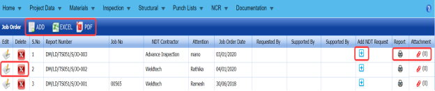
5.11.1 Add NDT Job Order
If you want to add an NDT job order, do the following,
- Click
 (ADD button) in the Job Order page. See Fig 5.11.
A new window opens to add an NDT job order.
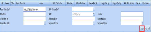
 Note: The fields notified with a symbol (*) are mandatory. You must enter the relevant details in that fields before saving.
 Tip: A report number for a new job order will be updated automatically in the Report Number box.
 -
In the NDT Contractor box, select the name of an NDT contractor from a drop-down list.
-
In the Attention box, enter any note if you want for attention.
-
In the Date box, select the date of adding an NDT job order.
-
In the Job No box, enter the job number.
-
In the Requested By box, enter the name of a person who has requested for an NDT job order.
-
In the Requested Date box, select requested date of an NDT job order.
-
In the Supported By boxes, enter the name of a project lead and a HOD, respectively.
-
Click Save.


The NDT job order is successfully added.
5.11.2 Add an NDT request
- Click
 (Add icon) of the respective job order in the Add NDT Request column of the Job Order See Fig 5.13.
A new window shows a list of added NDT request.
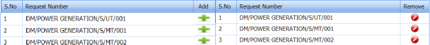
-
If you want to add any request, click
 (Add icon) of the respective request.
The added NDT request will be assigned under the respective job order.
- If you want to delete any request, click
 (Delete icon) of the respective request.


5.11.3 Attach a File into an NDT Job Order
If you want to attach any file with any NDT job order listed in the Job Order page, follow the procedures given in the topic “Attach a file into a client master drawing” in the Client Master Drawing section.
5.11.4 Print an NDT Job Order Report
If you want to print an NDT job order report, click  (print icon) provided in the Report column of the Job Order page. See Fig 5.11.
5.11.5 Edit Any NDT Job Order
If you want to edit any existing NDT job order in the Job Order page, do the following,
-
Click
 (Edit icon) in the Edit column for the respective NDT job order. See Fig 5.11.
A new window opens to edit the job order.
- Click any box where you want to edit the details, and then edit the details in the respective box.
-
Click Save.

5.11.6 Export NDT Job Order List
You can export a list of NDT job order added in the Job Order page in the pdf and excel formats. To know how to export, see the topic, “Export Areas list” in the Area option.
5.12 NDT Job Verification
The NDT Job Verification tab helps you to add an NDT job verification request. This tab helps the NDT contractor to verify the quantity of job done based on the request issued. If you want to navigate NDT Job Verification,
- Click the NDT Job Verification tab in the Inspection menu.
The Job Verification page opens.

Figure 5.12: Job Verification page
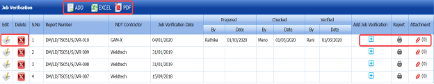
5.12.1 Add NDT Job Verification
If you want to add an NDT job verification, do the following,
- Click
 (ADD button) in the Job Verification page. See Fig 5.12.
A new window opens to add an NDT job verification request.
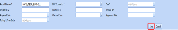
 Note: The fields notified with a symbol (*) are mandatory. You must enter the relevant details in that fields before saving.
 Tip: A report number for a new job verification will be updated automatically in the Report Number box.
 -
In the NDT Contractor box, select the name of an NDT contractor from a drop-down list.
-
In the Date box, select the date of adding an NDT job verification request.
-
In the Job No box, enter the job number.
-
In the Prepared By box, enter the name of a person who prepared the NDT job verification request.
- In the Prepared Date box, select prepared date of the NDT job verification request.
-
In the Checked By box, enter the name of a person who has checked the request.
-
In the Checked Date box, select checked date of the request.
- In the Verified By box, enter the name of a person who has verified the request.
-
Click Save.

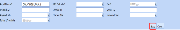


The NDT job verification request is successfully added.
5.12.2 Attach a File into an NDT Job Verification Request
If you want to attach any file with any NDT job verification request listed in the Job Verification page, follow the procedures given in the topic “Attach a file into a client master drawing” in the Client Master Drawing section.
5.12.3 Print an NDT Job Verification Report
If you want to print an NDT job verification report, click (print icon) provided in the Report column of the Job Verification page. See Fig 5.12.
5.12.4 Edit Any NDT Job Verification Request
If you want to edit any existing NDT job verification request in the Job Verification page, do the following,
- Click
 (Edit icon) in the Edit column for the respective NDT job verification request. See Fig 5.12.
A new window opens to edit the job order.
- Click any box where you want to edit the details, and then edit the details in the respective box.
-
Click Save.

5.12.5 Export NDT Job Verification Request List
You can export a list of NDT job verification request added in the Job Verification page in the pdf and excel formats. To know how to export, see the topic, “Export Areas list” in the Area option.
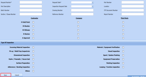
5.13 Survey form
The Survey form tab in the Inspection menu helps you to add a survey form. To navigate the Survey form,
- Click the Survey form tab in the Inspection menu.
The Survey form page opens.

Figure 5.13: Survey form page
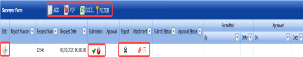
5.13.1 Add a Survey Form
If you want to add a survey form, do the following,
- Click
 (ADD button) in the Survey form page. See Fig 5.13.
A new window opens to add a survey form.

 Note: The fields notified with a symbol (*) are mandatory. You must enter the relevant details in that fields before saving.
 -
In the Report Number box, enter the report number of the survey form.
-
In the Request Date box, select the request date of the survey form.
-
In the Part Number box, enter the part number for the survey form.
-
In the Part Description box, enter the description for the added part number.
-
In the Inspection Request Date box, select the inspection request date.
-
In the Location box, enter the location where the inspection to be done.
-
In the Batch Number box, enter the batch number for the survey form.
-
In the Drawing Number box, enter the drawing number for the survey form.
-
In the Inspection and Test Plan (ITP) Document Number box, enter ITP document number.
-
In the Section / Clause Number box, enter the section / clause number.
-
In the Reference Number box, enter the reference number.
-
In the Report Number box, enter the report number.
-
In the Report Number box, enter the report number.
-
In the Type of Inspection option, select the required inspection types from the given inspection type list.
-
Click Save.


The survey form is successfully added.
5.13.2 Attach a File into a Survey Form
If you want to attach any file with any survey form added in the Survey form page, follow the procedures given in the topic “Attach a file into a client master drawing” in the Client Master Drawing section.
5.13.3 Submit and Approve a Survey Form
Once you have added the surveyor, the Submission column in the Survey form page is appeared with  (Submit and Reject icons).
-
If you want to submit the survey form, click
 (Submit icon) in the Submission column. Otherwise click
  (Reject icon) to reject the survey form.
Once you have submitted the survey form, the Approval column in the Survey form page is appeared with
 (Accept and Reject icons).
 - If you want to approve the survey form, click
 (Submit icon) in the Approval Otherwise click
  (Reject icon) to reject the survey form.


5.13.4 Print a Structural Survey Report
If you want to print a structural survey report, click  (print icon) provided in the Report column of the Survey form page. See Fig 5.13.
5.13.5 Edit Any Survey Form
If you want to edit any existing survey form in the Survey form page, do the following,
- Click
 (Edit icon) in the Edit column for the respective survey form. See Fig 5.13.
A new window opens to edit the survey form.
-
Click any box where you want to edit the details, and then edit the details in the respective box.
-
Click Save.

5.13.6 Export Survey Form List
You can export a list of survey forms added in the Survey Form page in the pdf and excel formats. To know how to export, see the topic, “Export Areas list” in the Area option.
5.14 Dimensional Inspection Request
The Dimensional Inspection Request tab in the Inspection menu helps you to add a dimensional inspection request. To navigate to the dimensional inspection request adding page,
- Click Dimensional Inspection Request in the Inspection menu.
The Dimensional Inspection Request page opens.

Figure 5.14: Dimensional Inspection Request page
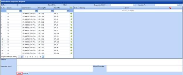
5.14.1 Add a Dimensional Inspection Request
If you want to add a new dimensional inspection request, do the following steps.
- In the Inspection Date box, select the date of dimensional inspection.
-
In the Location box, select the location where the dimensional inspection to be performed.
Before saving the added dimensional inspection request, you must add spools. You can add multiple spools for one dimensional inspection request.
 Note: The page shows a list of added spools. If you want to view the specific spools, use the filter options provided in the System, Line Number, Drawing Number, and Spool Number columns.
 - Click
 (Add icon) of the respective spool which you want to add.
The added spools will be moved to the right side of the page.
-
In the Remarks box, enter your remarks if any.
-
In the Inspection Item box, enter the details of inspection items.
-
Click Save.


The dimensional inspection request will be added and listed in the Dimensional Inspection List page.
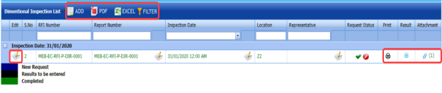
5.15 Dimensional Inspection List
The Dimensional Inspection List tab helps you to view and edit the dimensional inspection request, which is added by using the Dimensional Inspection Request tab. This tab also allows you to add a new dimensional inspection request.
- Click Dimensional Inspection List in the Inspection menu.
The Dimensional Inspection List page opens with a list of added dimensional inspection requests.

Figure 5.15: Dimensional Inspection List page
5.15.1 Add a Dimensional Inspection Request
If you want to add a dimensional inspection request, do the following steps,
- Click
 (ADD button) in the Dimensional Inspection List page.
The system redirects you into the Dimensional Inspection Request page. To know how to add a dimensional inspection request, See the topic, “Add a Dimensional Inspection Request”.

Once you have added the dimensional inspection request, you must submit the added request to perform the dimensional inspection.
5.15.2 Add Representative for Added Dimensional Inspection Request
If you want to add a representative for any added dimensional inspection request,
- Click
 (Edit icon) in the Representative column for the respective spool release request.
The Edit Form window opens.
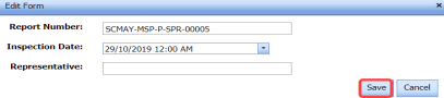
- In the Inspection Date box, select the date of inspection.
-
In the Representative box, enter the name of a representative.
-
Click Save.


5.15.3 Edit Any Dimensional Inspection Request
If you want to edit any existing dimensional inspection request in the Dimensional Inspection List page, do the following,
- Click
 (Edit icon) in the Edit column for the respective dimensional inspection request. See Fig 5.15.
The page opens with the details of the selected dimensional inspection request.
- Click any box where you want to edit the details, and then edit the details in the respective box.
-
Click Save.

5.15.4 Submit a Dimensional Inspection Request
Once you have added the dimensional inspection request, the Request Status column in the Dimensional Inspection List page is appeared with (Submit and Reject icons). See Fig 5.15.
- If you want to submit the dimensional inspection request, click
 (Submit icon) in the Request Status Otherwise click
  (Reject icon) to reject the request.


The submitted request will be moved to for the dimensional inspection.
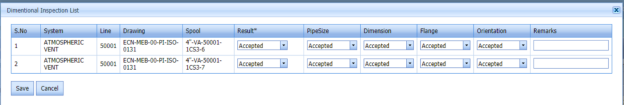
5.15.5 Add Results of Dimensional Inspection
After completing the dimensional inspection for the added request, you can add the inspection result details. To add results, do the following steps,
- Click
 (Add icon) in the Results column of the respective request.
The Dimensional Inspection List window opens with a list of added spools.

-
In the Result column, select the result for each spool from the given result options.
-
In the Pipe Size column, select the result of pipe size.
-
In the Dimension column, select the result of pipe dimension.
-
In the Flange column, select the result of flange.
-
In the Orientation column, select the result of orientation.
-
In the Remarks box, enter your remarks if any.
-
Click Save.

5.15.6 View a Dimensional Inspection Report
If you want to view a dimensional inspection report, click (print icon) provided in the Print column of the Dimensional Inspection List page. See Fig 5.15.
5.15.7 Attach a File into a Dimensional Inspection Request
If you want to attach a file with an existing dimensional inspection request listed in the Dimensional Inspection List page, you can attach the file by using  (Attach icon) in the Attachment column. To know how to attach, follow the procedures given in the topic “Attach a file into a client master drawing”.
5.15.8 Export Dimensional Inspection Request List
You can export a list of dimensional inspection requests added in the Dimensional Inspection List page in both the pdf and excel formats by using  (PDF button) and
  (Excel button). To know how to export, see the topic, “Export Areas list”.
5.15.9 Filter Dimensional Inspection Request
If you want to filter any dimensional inspection request in the Dimensional Inspection List page, you can use  (FILTER button) located on the Dimensional Inspection List page. To know how to filter, see the topic, ”Filter Any Area”.
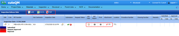
5.16 Inspection Release Note
The Inspection Release Note tab in the Inspection menu helps you to add an inspection release note. If you want to navigate the inspection release note adding page,
- Click Inspection Release Note in the Inspection menu.
The Inspection Release Note page opens.

Figure 5.16: Inspection Release Note page
5.16.1 Add an Inspection Release Note
If you want to add an inspection release note, do the following,
- Click
 (ADD button) in the Inspection Release Note page.
A new window opens to add an Inspection release note.
 Note: The fields notified with a symbol (*) are mandatory. You must enter the relevant details in that fields before saving.
 -
In the Sub Contractor Name box, select a sub-contractor from a drop-down list.
-
In the Inspection Date & Time box, select the date and time of inspection.
-
In the Location box, select a location where the inspection to be held.
-
In the System/Area box, enter the name of area/system.
-
In the Sub System No box, enter the sub system number.
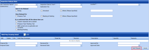
- In the Item to be Released field, select the detail of the item to be released that is whether Piping or Structural. If another item means select the checkbox of Others and enter the item detail.
- In the Item to be Released for field, select the reason of the item to be released for that is whether for Pressure Test or Blasting & Painting. If any other reason means select the checkbox of Others and enter the reason.
-
In the Sheet No box, enter the sheet number.
-
In the Revision box, enter the revision for the weld map drawing.
-
In the Description box, enter the description for the weld map drawing.
-
In the Quantity box, enter the quantity of the weld map drawing.
-
In the Remarks box, enter your remarks if any.
-
Click Update.
The weld map drawing is updated.
-
In the Prepared By box, enter the name of a person who has prepared the inspection release note.
- In the Prepared Date box, select the prepared date of the inspection release note.
-
In the Reviewed By box, enter the name of a person who has reviewed the inspection release note.
- In the Reviewed Date box, select the reviewed date of the inspection release note.
- In the Approved By box, enter the name of a person who has approved the inspection release note.
- In the Approved Date box, select the approved date of the inspection release note.
-
In the Remarks box, enter your remarks if any.
-
Click Send Request.


The inspection release will be added and listed in the Inspection Release Note page.
5.16.2 Add RFI Data for the Added Inspection Release Note
If you want to add RFI data for the added inspection release note, do the following,
- Click
 (Edit icon) in the RFI Data column of the Inspection Release Note See Fig 5.16.
The RFI Inspection Request List window opens.

-
In the Inspection From box, enter the detail from where the inspection should start.
-
In the Inspection To box, enter the detail to where the inspection should end.
-
In the Inspection Details option, select 1st Inspection, 2nd Inspection or 3rd Inspection according to the inspection details.
-
In the Others box, enter any other inspection related details.
-
In the Refer to Report No box, enter the report number for reference.
-
In the RFI Date box, choose the RFI date.
- In the Inspection Result option, if the inspection result is accepted, select Accepted otherwise select Rejected.
-
In the Remarks box, enter your remarks if any.
-
In the Inspected by box, enter the name of a person who has done inspection.
-
In the Inspected Date box, choose the date of inspection.
-
In the Witnessed By box, enter the name of the witnessed person.
-
In the Witnessed Date box, choose the date of witnessed.
-
In the PCML Rep Name box, enter the representative name of PCML.
-
In the PCML Rep Date box, choose the PCML rep date.
-
In the MEB Rep Name box, enter the representative name of MEB.
-
In the MEB Rep Date box, choose MEB rep date.
-
Click Save.


The RFI data is successfully added.
5.16.3 Submit and Approve an NDT Inspection Generic
Once you have added the inspection release note, the Submission column in the Inspection Release Note page is appeared with  (Submit and Reject icons).
- If you want to submit the inspection release note, click
 (Submit icon) in the Submission Otherwise click
  (Reject icon) to reject the request.
Once you have submitted the inspection release note, the Request Status column in the Inspection Release Note page is appeared with
 (Approve and Reject icons).
 - If you want to approve the inspection release note, click
 (Approve icon) in the Request Status Otherwise click
  (Reject icon) to reject the request.


5.16.4 Print an RFI Report
If you want to print an RFI report, click  (print icon) provided in the RFI Report column of the Inspection Release Note page. See Fig 5.16.
5.16.5 Print an Inspection Release Note
If you want to print an inspection release note, click  (print icon) provided in the Print column of the Inspection Release Note page. See Fig 5.16.
5.16.6 Attach a File into an Inspection Release Note
If you want to attach a file with an inspection release note added in the Inspection Release Note page, follow the procedures given in the topic “Attach a file into a client master drawing” in the Client Master Drawing section.
5.16.7 Edit Any Inspection Release Note
If you want to edit any existing inspection release note in the Inspection Release Note page, do the following,
- Click
 (Edit icon) in the Edit column for the respective NDT inspection generic. See Fig 5.16.
A new window opens to edit the inspection release note.
- Click any box where you want to edit the details, and then edit the details in the respective box.
-
Click Save.

5.16.8 Export Inspection Release Note List
You can export a list of inspection release notes added in the Inspection Release Note page in the pdf and excel formats. To know how to export, see the topic, “Export Areas list” in the Area option.
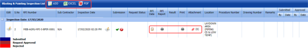
5.17 Blasting and Painting Inspection Report
The Blasting and Painting Inspection Report tab in the Inspection menu helps you to add a blasting and painting inspection report. If you want to navigate the blasting and painting inspection report adding page,
- Click Blasting and Painting Inspection Report in the Inspection menu.
The Blasting and Painting Inspection List page opens.

Figure 5.17: Blasting and Painting Inspection List page
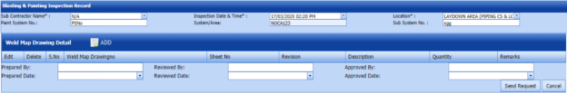
5.17.1 Add a Blasting and Painting Inspection Report
If you want to add a blasting and painting inspection report, do the following,
- Click
 (ADD button) in the Blasting and Painting Inspection List page.
A new window opens to add the blasting and painting inspection report details.
 Note: The fields notified with a symbol (*) are mandatory. You must enter the relevant details in that fields before saving.
 - In the Sub Contractor Name box, select a sub-contractor from a drop-down list.
-
In the Inspection Date & Time box, select the date and time of inspection.
-
In the Location box, select a location where the inspection to be held.
-
In the Paint System No box, enter the paint system number.
-
In the System/Area box, enter the name of area/system.
-
In the Sub System No box, enter the sub system number.
Before saving the blasting and painting inspection report, you must add the weld map drawing detail.
-
Click
 (ADD button) in the Weld Map Drawing Detail window.
The Edit Form window shows a new window to add the details of weld map drawing.

-
In the Weld Map Drawing No box, enter the weld map drawing number.
-
In the Sheet No box, enter the sheet number.
-
In the Revision box, enter the revision for the weld map drawing.
-
In the Description box, enter the description for the weld map drawing.
-
In the Quantity box, enter the quantity of the weld map drawing.
-
In the Remarks box, enter your remarks if any.
-
Click Update.
The weld map drawing is updated.
- In the Prepared By box, enter the name of a person who has prepared the blasting and painting inspection report.
-
In the Prepared Date box, select the prepared date of the blasting and painting inspection report.
-
In the Reviewed By box, enter the name of a person who has reviewed the blasting and painting inspection report.
-
In the Reviewed By box, enter the name of a person who has reviewed the blasting and painting inspection report.
-
In the Approved By box, enter the name of a person who has approved the blasting and painting inspection report.
-
In the Approved Date box, select the approved date of the blasting and painting inspection report.
-
In the Remarks box, enter your remarks if any.
-
Click Send Request.

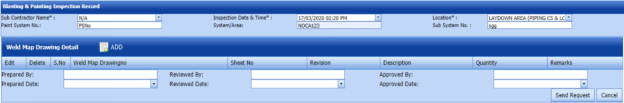


The blasting and painting inspection report will be added and listed in the Blasting and Painting Inspection List page.
5.17.2 Add RFI Data for the Added Blasting and Painting Inspection Report
If you want to add RFI data for the added blasting and painting inspection report, do the following,
- Click
 (Edit icon) in the RFI Data column of the Blasting and Painting Inspection List See Fig 5.17.
The RFI Inspection Request List window opens.

- In the Inspection From box, enter the detail from where the inspection should start.
-
In the Inspection To box, enter the detail to where the inspection should end.
- In the Inspection Details option, select 1stInspection, 2nd Inspection or 3rd Inspection according to the inspection details.
-
In the Others box, enter any other inspection related details.
-
In the Refer to Report No box, enter the report number for reference.
-
In the RFI Date box, choose the RFI date.
-
In the Inspection Result option, if the inspection result is accepted, select Accepted otherwise select Rejected.
-
In the Remarks box, enter your remarks if any.
-
In the Inspected by box, enter the name of a person who has done inspection.
-
In the Inspected Date box, choose the date of inspection.
-
In the Witnessed By box, enter the name of the witnessed person.
-
In the Witnessed Date box, choose the date of witnessed.
-
In the PCML Rep Name box, enter the representative name of PCML.
-
In the PCML Rep Date box, choose the PCML rep date.
-
In the MEB Rep Name box, enter the representative name of MEB.
-
In the MEB Rep Date box, choose MEB rep date.
-
Click Save.


The RFI data is successfully added.
5.17.3 The RFI data is successfully added.
Once you have added the blasting and painting inspection report, the Submission column in the Blasting and Painting Inspection List page is appeared with  (Submit and Reject icons).
- If you want to submit the blasting and painting inspection report, click
 (Submit icon) in the Submission Otherwise click
  (Reject icon) to reject the request.
Once you have submitted the blasting and painting inspection report, the Request Status column in the Blasting and Painting Inspection List page is appeared with (Approve and Reject icons).
- If you want to approve the blasting and painting inspection report, click
 (Approve icon) in the Request Status Otherwise click
  (Reject icon) to reject the request.
Once you have approved the blasting and painting inspection report, the Result column will be enabled with (Add icon) to add the blasting and painting inspection results.
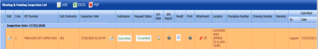


517.4 Add Blasting and Painting Inspection Results
If you want to add the blasting and painting inspection results,
- Click
 (Add icon) in the Result column of the Blasting and Painting Inspection List page.
The page shows a new window.

- Click
 (Edit icon) in the Edit column.
The page shows the Surface Preparation, Paint Preparation, and Paint Application windows.
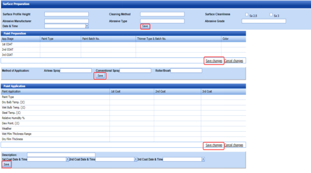
-
In the Surface Profile Height box, enter the surface profile height value.
-
In the Cleaning Method box, enter the cleaning method detail.
-
In the Surface Cleanliness box, select the surface cleanliness level.
-
In the Abrasive Manufacturer box, enter the abrasive manufacturer detail.
-
In the Abrasive Type box, enter the type name of abrasive.
-
In the Abrasive Grade box, enter the grade level of abrasive.
-
In the Date & Time box, select the date and time.
-
Click Save.
- In the Paint Preparation window, enter the detail of 1st coat, 2nd coat and 3rd coat in the respective columns.
-
Click Save changes.
-
In the Airless Spray box, enter the airless spray method detail.
-
In the Conventional Spray box, enter the conventional spray method detail.
-
In the Roller/Brush box, enter the roller/brush detail.
-
Click Save.
-
In the Paint Application window, enter the detail of 1st coat, 2nd coat and 3rd coat in the respective columns.
-
Click Save changes.
-
In the Description box, enter the description for the inspection.
-
In the 1st Coat Date & Time box, select the date and time of 1st coat.
-
In the 2nd Coat Date & Time box, select the date and time of 2nd coat.
-
In the 3rd Coat Date & Time box, select the date and time of 3rd coat.
-
Click Save.


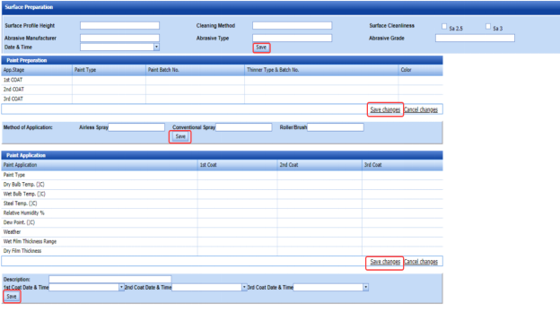
5.17.5 Print an RFI Report
If you want to print an RFI report, click  (print icon) provided in the RFI Report column of the Blasting and Painting Inspection List page. See Fig 5.17.
5.17.6 Print a Blasting and Painting Inspection Report
If you want to print a blasting and painting inspection report, click  (print icon) provided in the Print column of the Blasting and Painting Inspection List page. See Fig 5.17.
5.17.7 Attach a File into a Blasting and Painting Inspection Report
If you want to attach a file with a blasting and painting inspection report added in the Blasting and Painting Inspection List page, follow the procedures given in the topic “Attach a file into a client master drawing” in the Client Master Drawing section.
5.17.8 Edit Any Blasting and Painting Inspection Report
If you want to edit any existing blasting and painting inspection report in the Blasting and Painting Inspection List page, do the following,
- Click
 (Edit icon) in the Edit column for the respective blasting and painting inspection report. See Fig 5.17.
A new window opens to edit the blasting and painting inspection report.
-
Click any box where you want to edit the details, and then edit the details in the respective box.
-
Click Save.

5.17.9 Export Blasting and Painting Inspection Report List
You can export a list of blasting and painting inspection reports added in the Blasting and Painting Inspection List page in the pdf and excel formats. To know how to export, see the topic, “Export Areas list” in the Area option.
5.18 Painting and Coating Final Inspection Report
The Painting and Coating FIR tab in the Inspection menu helps you to add a painting and coating inspection report. If you want to navigate the painting and coating inspection report adding page,
- Click Painting and Coating FIR in the Inspection menu.
The Painting and Coating FIR page opens.

Figure 5.18: Painting and Coating FIR page
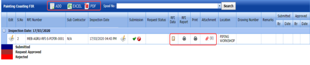
5.18.1 Add a Painting and Coating FIR
If you want to add a painting and coating FIR, do the following,
- Click
 (ADD button) in the Painting and Coating FIR page.
A new window opens to add the painting and coating inspection report details.
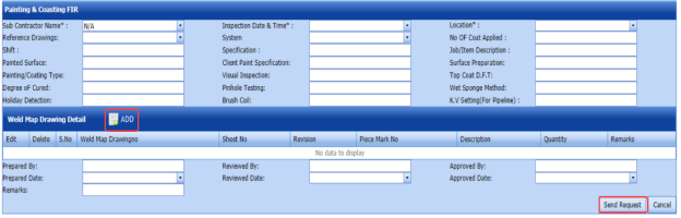
 Note: The fields notified with a symbol (*) are mandatory. You must enter the relevant details in that fields before saving.
 - In the Sub Contractor Name box, select a sub-contractor from a drop-down list.
- In the Sub Contractor Name box, select a sub-contractor from a drop-down list.
-
In the Location box, select the location where the painting and coating inspection to be performed.
- In the Reference Drawing box, select a reference drawing from a drop-down list.
-
In the System box, select a system from a drop-down list.
-
In the No of Coat Applied box, enter the number of applied coating.
-
In the Shift box, enter the shift detail.
-
In the Specification box, enter the specification detail.
-
In the Job/Item Description box, enter the description for the job/item.
-
In the Painted Surface box, enter the painted surface detail.
-
In the Client Paint Specification box, enter the client paint specification detail.
-
In the Surface Preparation box, enter the surface preparation detail.
-
In the Painting/Coating Type box, enter the painting/coating type.
-
In the Visual Inspection box, enter the visual inspection detail.
-
In the Top Coat D.F.T box, enter the top coat detail.
-
In the Degree of Cured box, enter the degree of cured.
-
In the Pinhole Testing box, enter the pinhole testing detail.
-
In the Wet Sponge Method box, enter the wet sponge method detail.
-
In the Holiday Detection box, enter the holiday detection detail.
-
In the Brush Coil box, enter the brush coil detail.
-
In the K.V Setting (For Pipeline) box, enter the K.V setting detail for pipeline.
Before saving the painting and coating inspection report, you must add the weld map drawing detail.
- Click
 (ADD button) in the Weld Map Drawing Detail
The Edit Form window shows a new window to add the details of weld map drawing.
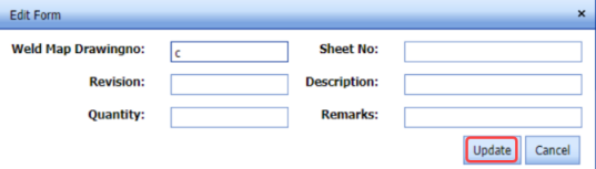
- In the Weld Map Drawing No box, enter the weld map drawing number.
-
In the Sheet No box, enter the sheet number.
-
In the Revision box, enter the revision for the weld map drawing.
-
In the Description box, enter the description for the weld map drawing.
-
In the Quantity box, enter the quantity of the weld map drawing.
-
In the Remarks box, enter your remarks if any.
-
Click Update.
The weld map drawing is updated.
-
In the Prepared By box, enter the name of a person who has prepared the painting and coating inspection report.
-
In the Prepared By box, enter the name of a person who has prepared the painting and coating inspection report.
- In the Reviewed By box, enter the name of a person who has reviewed the painting and coating inspection report.
- In the Reviewed Date box, select the reviewed date of the painting and coating inspection report.
- In the Approved By box, enter the name of a person who has approved the painting and coating inspection report.
- In the Approved Date box, select the approved date of the painting and coating inspection report.
-
In the Remarks box, enter your remarks if any.
-
Click Send Request.


The painting and coating inspection report will be added and listed in the Painting and Coating FIR page.
5.18.2 Add RFI Data for the Added Painting and Coating FIR
If you want to add RFI data for the added painting and coating inspection report, do the following,
- Click
 (Edit icon) in the RFI Data column of the Painting and Coating FIR page. See Fig 5.18.
The RFI Inspection Request List window opens.
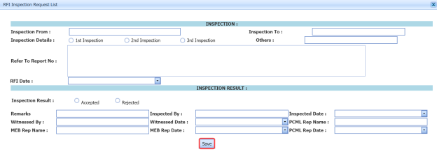
- In the Inspection From box, enter the detail from where the inspection should start.
-
In the Inspection To box, enter the detail to where the inspection should end.
- In the Inspection Details option, select 1stInspection, 2nd Inspection or 3rd Inspection according to the inspection details.
-
In the Others box, enter any other inspection related details.
-
In the Refer to Report No box, enter the report number for reference.
-
In the RFI Date box, choose the RFI date.
- In the Inspection Result option, if the inspection result is accepted, select Accepted otherwise select Rejected.
- In the Remarks box, enter your remarks if any.
-
In the Inspected by box, enter the name of a person who has done inspection.
-
In the Inspected Date box, choose the date of inspection.
-
In the Witnessed By box, enter the name of the witnessed person.
-
In the Witnessed Date box, choose the date of witnessed.
-
In the PCML Rep Name box, enter the representative name of PCML.
-
In the PCML Rep Date box, choose the PCML rep date.
-
In the MEB Rep Name box, enter the representative name of MEB.
-
In the MEB Rep Date box, choose MEB rep date.
-
Click Save.


The RFI data is successfully added.
5.18.3 Submit and Approve a Painting and Coating FIR
Once you have added the painting and coating inspection report, the Submission column in the Painting and Coating FIR page is appeared with (Submit and Reject icons).
- If you want to submit the painting and coating inspection report, click
 (Submit icon) in the Submission column. Otherwise click
  (Reject icon) to reject the request.
Once you have submitted the painting and coating inspection report, the Request Status column in the Painting and Coating FIR page is appeared with
 (Approve and Reject icons).
 - If you want to approve the painting and coating inspection report, click
 (Approve icon) in the Request Status Otherwise click
  (Reject icon) to reject the request.


5.18.4 Print an RFI report
If you want to print an RFI report, click (print icon) provided in the RFI Report column of the Painting and Coating FIR page. See Fig 5.18.
5.18.5 Print a Painting and Coating FIR
If you want to print a painting and coating inspection report, click  (print icon) provided in the Print column of the Painting and Coating FIR page. See Fig 5.18.
5.18.6 Attach a File into a Painting and Coating Inspection Report
If you want to attach a file with a painting and coating inspection report added in the Painting and Coating FIR page, follow the procedures given in the topic “Attach a file into a client master drawing” in the Client Master Drawing section.
5.18.7 Edit Any Painting and Coating FIR
If you want to edit any existing painting and coating inspection report in the Painting and Coating FIR page, do the following,
- Click
 (Edit icon) in the Edit column for the respective painting and coating inspection report. See Fig 5.18.
A new window opens to edit the painting and coating inspection report.
- Click any box where you want to edit the details, and then edit the details in the respective box.
-
Click Save.

5.18.8 Export Painting and Coating FIR list
You can export a list of painting and coating inspection reports added in the Painting and Coating FIR page in the pdf and excel formats. To know how to export, see the topic, “Export Areas list” in the Area option.
5.18.9 Filter Painting and Coating FIR
If you want to filter any specific painting and blasting inspection request in the Painting and Coating FIR page, you can filter the request based on the Spool No filter box. 
5.19 RFI Hydro Pressure
Hydro Pressure Inspection is the technique in which pipes used in the structural project, are tested at required design pressure of the pipes to check the leak and strength. You can add a request for hydro pressure inspection by using the RFI Hydro Pressure tab in the Inspection menu.
5.19.1 Add an RFI Hydro Pressure Request
If you want to add an RFI hydro pressure request, do the following steps,
- Click RFI Hydro Pressure in the Inspection menu.
The RFI Hydro Pressure page opens.
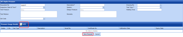
Figure 5.19: RFI Hydro Pressure page
-
In the Inspection Date & Time box, select the inspection date and time.
-
In the Description box, enter the description for the hydro pressure inspection.
-
In the Drawing No box, select a drawing number.
-
In the System box, select a system.
-
In the Test Type box, select a test type.
-
In the Test Pressure box, enter the test pressure value.
-
In the Design Pressure box, enter the design pressure value.
-
In the Classification box, enter the classification detail.
-
In the Holding Time box, enter the holding time range.
-
In the Test Medium box, enter the test medium detail.
-
In the Job Code box, enter the job code.
-
In the Remarks box, enter your remarks if any.
Before saving the added NDT request, you must add the pressure gauge details.
-
Click
 (ADD button) in the Pressure Gauge Details window.
-
In the Type of Test box, select a type of test.
-
In the Description box, enter the description detail.
-
In the Serial No box, enter the serial number.
-
In the Certificate No box, enter the certificate number.
-
In the Calibration Date box, select the calibration date.
-
In the Expiry Date box, select the expiry date.
-
Click Save Request.


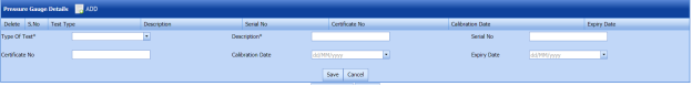
The hydro pressure inspection request will be added and listed in the RFI Hydro Pressure page.
5.20 View RFI Hydro Pressure
The View RFI Hydro Pressure tab helps you to view and edit the hydro pressure inspection request, which is added by using the RFI Hydro Pressure tab. This tab also allows you to add a new hydro pressure request.
- Click View RFI Hydro Pressure in the Inspection menu.
The RFI Hydro Pressure page opens with a list of added hydro pressure requests.
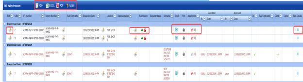
Figure 5.20: RFI Hydro Pressure page

5.20.1 Add a Hydro Pressure Inspection Request
If you want to add a hydro pressure inspection request, do the following steps,
- Click
 (ADD button) in the RFI Hydro Pressure page.
The system redirects you to a new page to add a new hydro pressure inspection request. To know how to add a hydro pressure inspection request, See the topic, “Add a Hydro Pressure Inspection Request”.

The system redirects you to a new page to add a new hydro pressure inspection request. To know how to add a hydro pressure inspection request, See the topic, “Add a Hydro Pressure Inspection Request”.
5.20.2 Edit Any Existing Hydro Pressure Inspection Request
If you want to edit any existing hydro pressure inspection request in the RFI Hydro Pressure page, do the following,
- Click
 (Edit icon) in the Edit column for the respective hydro pressure inspection request. See Fig 5.20.
The RFI Hydro Pressure page opens with the details of the selected hydro pressure inspection request.
-
Click any box where you want to edit the details, and then edit the details in the respective box.
-
Click Save.

5.20.3 Submit and Approve a Hydro Pressure Inspection Request
Once you have added the hydro pressure inspection request, the Submission column in the RFI Hydro Pressure page is appeared with (Submit and Reject icons).
- If you want to submit the hydro pressure inspection request, click
 (Submit icon) in the Submission Otherwise click
  (Reject icon) to reject the request.
Once you have submitted the hydro pressure inspection request, the Request Status column in the RFI Hydro Pressure page is appeared with
 (Approve and Reject icons).
 - If you want to approve the hydro pressure inspection request, click
 (Approve icon) in the Request Status Otherwise click
  (Reject icon) to reject the request.


The hydro pressure inspection request will be moved for hydro pressure inspection.
5.20.4 View a Hydro Pressure Inspection Report
If you want to view a hydro pressure inspection report, click  (print icon) provided in the Print column of the RFI Hydro Pressure page. See Fig 5.20.
5.20.5 Attach a File into a hydro pressure inspection Request
If you want to attach a file with any existing hydro pressure inspection request listed in the RFI Hydro Pressure page, you can attach the file by using  (Attach icon) in the Attachment column. To know how to attach, follow the procedures given in the topic “Attach a file into a client master drawing”.
5.20.6 View Signature Details of Inspectors
You can view the sign details of the inspectors such as QA, Sub contractor, Client, and Owner, once they completed the hydro pressure inspection and submitted the inspection result details including their signature. To view the signature details, click  (Sign icon) in the Sign Details column in the RFI Hydro Pressure page.
5.20.7 Export Hydro Pressure Inspection Request List
You can export a list of hydro pressure requests added in the RFI Hydro Pressure page in both the pdf and excel formats by using  (PDF button) and
  (Excel button). To know how to export, see the topic, “Export Areas list”.
5.20.8 Filter Hydro Pressure Inspection Request
If you want to filter any specific hydro pressure inspection request in the RFI Hydro Pressure page, you can use  (FILTER button) located on the RFI Hydro Pressure page. To know how to filter, see the topic, ”Filter Any Area”.
5.21 RFI Mechanical Completion Request
Mechanical completion takes place through all phases of the piping project, starting at equipment supplier and continuing through fabrication up to commissioning phase. Mechanical completion encompasses all disciplines. If you want to add an RFI mechanical completion request,
- Click RFI Mechanical Completion Request in the Inspection menu.
The RFI Mechanical Completion Request page opens.

Figure 5.21: RFI Mechanical Completion Request page
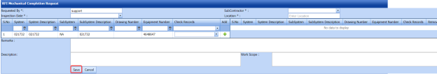
5.21.1 Add an RFI Mechanical Completion Request
If you want to add an RFI mechanical completion request, do the following steps,
- In the Sub Contractor box, select a sub-contractor from a drop-down list.
-
In the Inspection Date box, select the date of inspection.
-
In the Location box, enter the name of the location.
Before saving the added RFI mechanical completion request, you must add a system. You can add multiple system for one request.
 Note: The page shows a list of added systems. If you want to view the specific system, use the filter options provided in the System, Sub System, Drawing Number, Equipment Number and Check Records columns.
 -
Select
 (Add icon) of the respective system which you want to add.
The added system will be moved into the right side of the page.
-
In the Remarks box, enter your remarks if any.
-
In the Description box, enter the description for the request.
-
In the Work Scope box, enter the work scope detail.
-
Click Save.


The RFI mechanical completion request will be added and listed in the View RFI Mechanical Completion page.
5.22 View RFI Mechanical Completion
The View RFI Mechanical Completion tab helps you to view and edit the RFI mechanical completion request, which is added by using the RFI Mechanical Completion Request tab. This tab also allows you to add a new RFI mechanical completion request.
- Click View RFI Mechanical Completion in the Inspection menu.
The View RFI Mechanical Completion List page opens with a list of added RFI mechanical completion requests.

Figure 5.22: View RFI Mechanical Completion List page
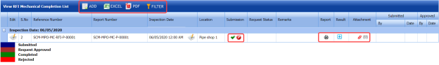
5.22.1 Add an RFI Mechanical Completion Request
If you want to add an RFI mechanical completion request, do the following steps,
- Click
 (ADD button) in the View RFI Mechanical Completion List page.
The system redirects you to a new page to add a new RFI mechanical completion request. To know how to add an RFI mechanical completion request, See the topic, “Add an RFI Mechanical Completion Request”.

Once you have added the RFI mechanical completion request, you must submit the added request to perform mechanical completion inspection.
5.22.2 Edit Any RFI Mechanical Completion Request
If you want to edit any existing mechanical completion request in the View RFI Mechanical Completion List page, do the following,
- Click
 (Edit icon) in the Edit column for the respective RFI mechanical completion request. See Fig 5.22.
The RFI Mechanical Completion Request page opens with the details of the selected RFI mechanical completion request.
-
Click any box where you want to edit the details, and then edit the details in the respective box.
-
Click Save.

5.22.3 Submit and Approve an RFI Mechanical Completion Request
Once you have added the RFI mechanical completion request, the Submission column in the RFI Mechanical Completion Request page is appeared with  (Submit and Reject icons).
- If you want to submit the mechanical completion request, click
 (Submit icon) in the Submission Otherwise click
  (Reject icon) to reject the request.
Once you have submitted the mechanical completion request, the Request Status column in the View RFI Mechanical Completion List page is appeared with
 (Approve and Reject icons).
 - If you want to approve the mechanical completion request, click
 (Approve icon) in the Request Status Otherwise click
  (Reject icon) to reject the request.
The mechanical completion request will be moved for mechanical completion inspection.


5.22.4 Add Results of Mechanical Completion Inspection
After completing the mechanical completion inspection for the added request, you can add the inspection result details. To add results, do the following steps,
- Click
 (Add icon) in the Results column of the respective request.
The Result window opens a list of test pack added for the particular request.

- In the Result column, select the result of each test pack from the given result options in the drop-down list.
-
In the Remarks column, enter your remarks if any.
-
Click Approve All & Save.


5.22.5 View a Mechanical Completion Inspection Report
If you want to view a mechanical completion inspection report, click  (print icon) provided in the Print column of the View RFI Mechanical Completion List page. See Fig 5.22.
5.22.6 Attach a File into a Mechanical Completion inspection Request
If you want to attach a file with any existing mechanical completion inspection request listed in the View RFI Mechanical Completion List page, you can attach the file by using  (Attach icon) in the Attachment column. To know how to attach, follow the procedures given in the topic “Attach a file into a client master drawing”.
5.22.7 Export Mechanical Completion Inspection Request List
You can export a list of mechanical completion inspection requests added in the View RFI Mechanical Completion List page in both the pdf and excel formats by using  (PDF button) and
  (Excel button). To know how to export, see the topic, “Export Areas list”
5.22.8 Filter Any Mechanical Completion Inspection Request
If you want to filter any specific mechanical completion inspection request in the View RFI Mechanical Completion List page, you can use  (FILTER button) located on the View RFI Mechanical Completion List page. To know how to filter, see the topic, ”Filter Any Area”.
5.23 RFI Static Commissioning
Static Commissioning take place when Mechanical completion is completed for a system or part of a system. If you want to add an RFI static commissioning request,
- Click RFI Static Commissioning in the Inspection menu.
The RFI Static Commissioning Request page opens.

Figure 5.23: RFI Static Commissioning Request page
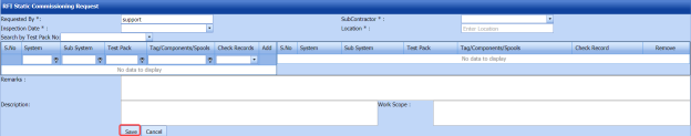
8.23.1 Add an RFI Static Commissioning Request
If you want to add an RFI static commissioning request, do the following steps,
- In the Sub Contractor box, select a sub-contractor from a drop-down list.
-
In the Inspection Date box, select the date of inspection.
-
In the Location box, enter the name of the location.
Before saving the added RFI static commissioning request, you must add a system. You can add multiple systems for one request.
 Note: The page shows a list of added systems. If you want to view the specific system, use the filter options provided in the System, Sub System, Drawing Number, Equipment Number and Check Records columns.
 - Select the checkbox of the respective system which you want to add.
The added systems will be moved into the right side of the page.
-
In the Remarks box, enter your remarks if any.
-
In the Description box, enter the description for the request.
-
In the Work Scope box, enter the work scope detail.
-
Click Save.

The RFI mechanical completion request will be added and listed in the View RFI Static Commissioning page.
5.24 View RFI Static Commissioning
The View RFI Static Commissioning tab helps you to view and edit the RFI static commissioning request, which is added by using the RFI Static Commissioning tab. This tab also allows you to add a new RFI static commissioning request.
- Click View RFI Static Commissioning in the Inspection menu.
The View RFI Static Commissioning List page opens with a list of added RFI static commissioning requests.
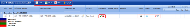
Figure 5.24: View RFI Static Commissioning List page
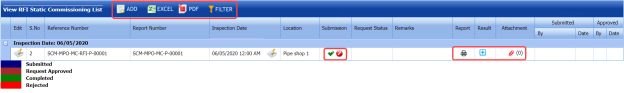
5.24.1 Add an RFI Static Commissioning Request
If you want to add an RFI static commissioning request, do the following steps,
- Click
 (ADD button) in the View RFI Static Commissioning List page.
The system redirects you to a new page to add a new RFI static commissioning request. To know how to add an RFI static commissioning request, See the topic, “Add an RFI Static Commissioning Request”.

Once you have added the RFI static commissioning request, you must submit the added request to perform the static commissioning.
5.24.2 Edit Any RFI Static Commissioning Request
If you want to edit any existing static commissioning request in the View RFI Static Commissioning List page, do the following,
- Click
 (Edit icon) in the Edit column for the respective RFI static commissioning request. See Fig 5.24.
The RFI Static Commissioning Request page opens with the details of the selected RFI request.
-
Click any box where you want to edit the details, and then edit the details in the respective box.
-
Click Save.

5.24.3 Submit and Approve an RFI Static Commissioning Request
Once you have added the RFI static commissioning request, the Submission column in the RFI Static Commissioning Request page is appeared with (Submit and Reject icons).
- If you want to submit the static commissioning request, click
 (Submit icon) in the Submission Otherwise click
  (Reject icon) to reject the request.
Once you have submitted the static commissioning request, the Request Status column in the View RFI Static Commissioning List page is appeared with
 (Approve and Reject icons).
 - If you want to approve the static commissioning request, click
 (Approve icon) in the Request Status Otherwise click
  (Reject icon) to reject the request.


The static commissioning request will be moved for static commissioning inspection.
5.24.4 Add Results of Static Commissioning Inspection
After completing the static commissioning inspection for the added request, you can add the inspection result details. To add results, do the following steps,
- Click
 (Add icon) in the Results column of the respective request.
The Result window opens a list of system added for the particular request.

-
In the Result column, select the result of each system from the given result options in the drop-down list.
-
In the Remarks column, enter your remarks if any.
-
Click Approve All & Save.


5.24.5 View a Static Commissioning Inspection Report
If you want to view a static commissioning inspection report, click  (print icon) provided in the Print column of the View RFI Static Commissioning List page. See Fig 5.24.
5.24.6 Attach a File into a Static Commissioning Inspection Request
If you want to attach a file with any existing static commissioning inspection request listed in the View RFI Static Commissioning List page, you can attach the file by using  (Attach icon) in the Attachment column. To know how to attach, follow the procedures given in the topic “Attach a file into a client master drawing”.
5.24.7 Export Static Commissioning Inspection Request List
You can export a list of static commissioning inspection requests added in the View RFI Static Commissioning List page in both the pdf and excel formats by using  PDF button) and
  (Excel button). To know how to export, see the topic, “Export Areas list”.
5.24.8 Filter Any Static Commissioning Inspection Request
If you want to filter any specific static commissioning inspection request in the View RFI Static Commissioning List page, you can use  (FILTER button) located on the View RFI Static Commissioning List page. To know how to filter, see the topic, ”Filter Any Area”.
5.25 Weekly Welders Performance Record
The Weekly Welders Performance Record tab in the Inspection menu helps you to view the welders performance record on a weekly basis. To view the report,
- Click Weekly Welders Performance Record in the Inspection menu.
The Weekly Welders Performance Record page opens.
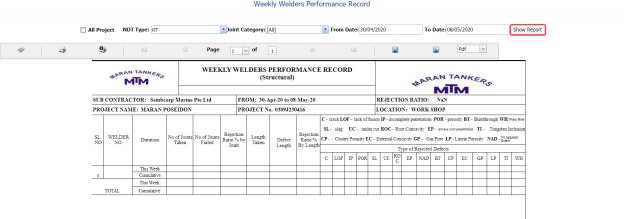
Figure 5.25: Weekly Welders Performance Record page
- If you want to view the weekly welders performance record for all project, select the checkbox of the All Project option.
-
In the NDT Type box, select an NDT type.
-
In the Joint Category box, select a joint category.
- In the From Date and To Date boxes, select the from and to dates.
-
Click Show Report.

5.25.1 Print Weekly Welders Performance Record
If you want to print a weekly welders performance record, use  and
and  (print icons) provided in the Weekly Welders Performance Record page.
- If you want to print the current page of the weekly welders performance record, click
 (print icon including the page number).
 - If you want to print all the pages of the weekly welders performance record, click
 (print icon).


5.25.2 View Weekly Welders Performance Record
You can view the weekly welders performance record in various formats by using the option  provided in the upper right corner of the Weekly Welders Performance Record page.
5.26 RFI Fit up Request (Unique Numbers)
The RFI Fit up Request tab in the Inspection menu allows you to add an RFI fit up request to check the fit-up quality of pipes and joints used in the structural project by a sub-contractor.
5.26.1 Add an RFI Fit up Request
If you want to add an RFI fit up request, do the following
- Click the RFI Fit up Request tab in the Inspection menu.
A new page opens to add an RFI fit up request.
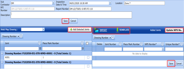
Figure 5.26: A page for adding an RFI fit up request
 Tip: A report number and an RFI number for a new RFI fit up request will be updated automatically in the Report Number and the RFI Number boxes, respectively.
 -
In the Sub Contractor box, select the name of a sub-contractor from a drop-down list.
-
In the Inspection Date & Time box, select the date of inspection.
-
In the Location box, enter the location detail.
-
In the Description box, enter the description for the inspection.
 Note: Before saving the added RFI fit up request, you must add the details of joints. You can add multiple joints for any added fit up request by using a box provided in the left side of the page. To know how to add joints, see the topic “Add joints for an RFI fit up request”.
 -
Click Save.
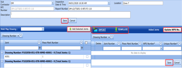


5.26.2 Add Joints for an RFI Fit up Request
This page shows a list of joints for the corresponding weld map drawing. If you want to add joints for any added RFI Fit up request, do the following,
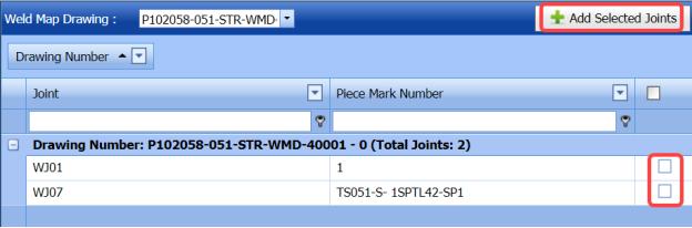
- In the Weld Map Drawing box, select a weld map drawing number from a drop-down list.
A list of joints including the piece mark numbers opens for the selected weld map drawing.
-
Click the check box of the respective joints.
-
Click
 (Add Selected Joints button).
The selected joints are moved into the Added Joints box located in the right side of the page.

- To update WPS number and unique number for the added joints, do one of the following steps,
-
-
If you want to update the WPS number for any joint, click the WPS Number column for the respective joint and then select the WPS number from a drop-down list.

- Enter the unique number for the corresponding joint number in the respective Unique Number column.
 Note: If you want to update the same WPS number of first joint to other joints, click (Update WPS No button). The WPS number for the first joint will be updated for other joints.
-
-
-
If you want to update the WPS number, unique number, piece mark number details together, do the following,
-
-
Click
 (TEMPLATE button) on the Added Joints box.
An excel worksheet will be downloaded with a pre-defined template. The template contains a list of added joints.

-
Enter the relevant details in the required columns on the excel worksheet.
- Once you have added the WPS, piece mark and other details in the excel worksheet, save the excel worksheet on your computer.
-
Click
 (IMPORT button).
A new window opens for importing the excel worksheet saved on your computer.

-
Click
 (Browse button) to select the excel worksheet to be uploaded.
 -
Select the excel worksheet you want to upload from your computer.
- Click
 (Upload button) to export the joint details that are included in the excel worksheet.
The details of the joints in the worksheet will be updated.
-
Click Save.
The RFI Fit up request is successfully added and moved to the View RFI Fit up tab.
-
-

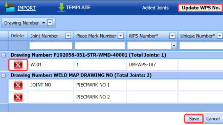
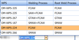


5.27 View RFI Fit up (Unique Numbers)
The View RFI Fit up tab helps you to view and edit the RFI fit up request, which added by using the RFI Fit up Request tab. This tab also allows you to add a new RFI fit up request.
- Click the View RFI Fit up tab in the Inspection menu.
The REQUEST FOR INSPECTION page opens with a list of added RFI fit up requests.

Figure 5.27: Request for Inspection page
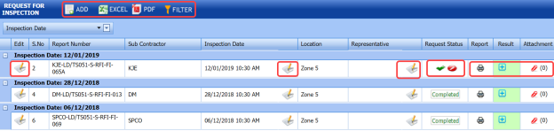
5.27.1 Add an RFI Fit up Request
If you want to add an RFI fit up request, do the following,
- Click
 (ADD button) in the REQUEST FOR INSPECTION page.
A new page opens to add an RFI fit up request. To know how to add an RFI fit up request, see the topic, “Add an RFI fit up request”.

Once you have added the RFI fit up request, you must submit the added request for inspection.
5.27.2 Submit an RFI Fit up Request
Once you have added the RFI fit up request, the Request Status column in the REQUEST FOR INSPECTION page is appeared with  (Submit and Reject icons). See Fig 5.27.
- If you want to submit the RFI fit up request, click
 (Submit icon) in the Request Status Otherwise click
  (Reject icon) to reject the request.


5.27.3 Add a Representative for Any RFI Fit up Request
If you want to add a representative for any added RFI fit up request,
- Click
 (Edit icon) in the Representative column for the respective RFI fit up request.
The Edit Form window opens.

-
In the Representative box, enter the name of a representative.
-
Click Save.

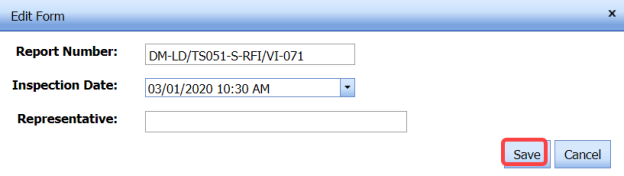
5.27.4 Print an RFI Fit up Report
If you want to print an RFI fit up report, click  (print icon) provided in the Report column of the REQUEST FOR INSPECTION page. See Fig 5.27.
5.27.5 Add Result Details of RFI Fit up Inspection
If you want to add the inspection results details of an added RFI fit up inspection request, do the following,
- Click
 (Add icon) in the Results column of the REQUEST FOR INSPECTION page.
The Joint Details window opens.

-
If you want to check and update the joint details automatically, click (Check and update button).
- If you want to update the joint details manually, do the following steps,
-
- Click the respective number in the WPS Number column and change the WPS number from a drop-down list.
- Click the respective number in the Unique Number column and change the unique number from a drop-down list.
-
Click Save changes.
-

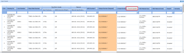
5.27.6 Attach a File into an RFI Fit up Request
If you want to attach any file with any RFI fit up request listed in the REQUEST FOR INSPECTION page, follow the procedures given in the topic “Attach a file into a client master drawing” in the Client Master Drawing section.
5.27.7 Edit Any RFI Fit up Request
If you want to edit any existing RFI fit up request in the REQUEST FOR INSPECTION page, do the following,
- Click
 (Edit icon) in the Edit column for the respective RFI fit up request. See Fig 5.27.
The page shows the added details of the RFI fit up request.
- Click any box where you want to edit the details, and then edit the details in the respective box.
- Click Save.

5.27.8 Export RFI Fit up Request List
You can export a list of RFI fit up request added in the REQUEST FOR INSPECTION page in the pdf and excel formats. To know how to export, see the topic, “Export Areas list” in the Area option.
5.27.9 Filter Any RFI Fit up Request
If you want to filter any RFI fit up request from the list of RFI fit up requests in the REQUEST FOR INSPECTION page, you can use  the (FILTER button). To know how to filter, see the topic, ”Filter Any Area”.
5.28 View Application for Inspection (AFI) Fit up (Unique Numbers)
The View AFI Fit up allows you to add a new AFI fit up request. This tab also helps you to view and edit the added AFI fit up request.
- Click the View AFI Fit up tab in the Inspection menu.
The INSPECTION REQUEST (AFI) page opens.
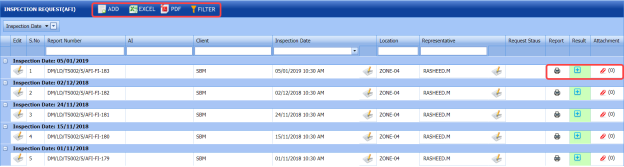
Figure 5.28: INSPECTION REQUEST (AFI) page

5.28.1 Add an AFI Fit up Request
If you want to add an AFI fit up request, do the following,
- Click
 (ADD button) in the INSPECTION REQUEST (AFI) page.
The AFI Request page opens to add an AFI fit up request.
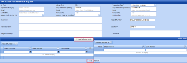
 Tip: A report number and RFI number for a new AFI fit up request will be updated automatically in the Report Number and RFI Number boxes.
 - In the Representative (AI) box, enter representative name for the application inspection and enter their email id and contact number in the Email and Contact No boxes, respectively.
-
In the Representative (Client) box, enter representative name from the client and enter their email id and contact number in the Email and Contact No boxes, respectively.
-
In the Inspection Date box, select the date of inspection.
- In the Representative (Contractor) box, enter representative name from the contractor and enter their email id and contact number in the Email and Contact No boxes, respectively.
-
In the Activity Code As Per ITP box, select the activity code as per ITP from a drop-down list.
-
In the Activity Code As Per Client box, select the activity code as per client from a drop-down list.
-
In the Location box, enter the location detail.
-
In the Description box, enter the description for the inspection.
-
In the Inspection Item box, enter the details of items to be inspected.
-
In the Subject Coverage box, enter the subject coverage detail.
-
In the Comments box, enter your comments if any.
 Note: Before saving the added AFI fit up request, you must add the details of joints. You can add multiple joints for any added fit up request by using a box provided in the left side of the page. To know how to add joints, see the topic “Add joints for an AFI fit up request”.
 - Click Save.


5.28.2 Add Joints for an AFI Fit up Request
If you want to add joints for any added AFI fit up request, do the following,
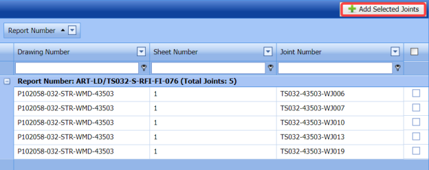
Once you enter the details to add an AFI fit up request, a list of joints including the joint numbers, sheet numbers, and drawing numbers opens.
- Click the check box of the respective joints.
-
Click
 (Add Selected Joints button).
The selected joints are moved into the Added Joints box located in the right side of the page.
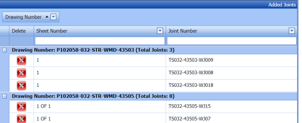
-
Click Save.


The selected joints are successfully added for the AFI fit up request.
Once you have added the RFI fit up request, you must submit the added request for inspection.
5.28.3 Submit an AFI Fit up Request
Once you have added the AFI fit up request, the Request Status column in the INSPECTION REQUEST (AFI) page is appeared with (Submit and Reject icons). See Fig 5.28.
- If you want to submit the AFI fit up request, click
 (Submit icon) in the Request Status Otherwise click
  (Reject icon) to reject the request.


5.28.4 Change the Added Representative for Any AFI Fit up Request
If you want to change the added representative for any AFI fit up request,
- Click
 (Edit icon) in the Representative column for the respective AFI fit up request.
The Edit Form window opens.
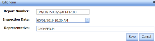
-
In the Representative box, edit the name of a representative.
-
Click Save.


5.28.5 Print an AFI Fit up Report
If you want to print an AFI fit up report, click  (print icon) provided in the Report column of the INSPECTION REQUEST (AFI) page. See Fig 5.28.
5.28.6 Add Result Details of AFI Fit up Inspection
If you want to update results for the AFI fit up inspection request, do the following,
- Click
 (Add icon) in the Results column of the INSPECTION REQUEST (AFI) page.
A new window opens.
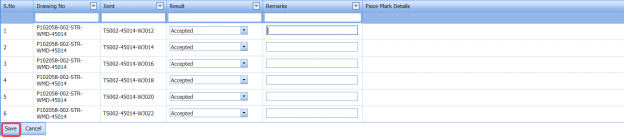
- In the Result column, select the results of AFI inspection from a drop-down list, for the respective drawing and joint numbers.
-
In the Remarks column, enter your remarks if any.
-
Click Save.

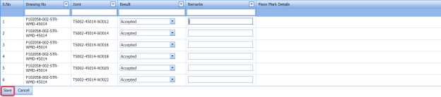
5.28.7 Attach a File into an AFI Fit up Request
If you want to attach any file with any AFI fit up request listed in the INSPECTION REQUEST (AFI) page, follow the procedures given in the topic “Attach a file into a client master drawing” in the Client Master Drawing section.
5.28.8 Edit Any AFI Fit up Request
If you want to edit any existing AFI fit up request in the INSPECTION REQUEST (AFI) page, do the following,
- Click
 (Edit icon) in the Edit column for the respective AFI fit up request. See Fig 5.28.
The page shows the added details of the AFI fit up request.
- Click any box where you want to edit the details, and then edit the details in the respective box.
-
Click Save.

5.28.9 Export AFI Fit up Request List
You can export a list of AFI fit up request added in the INSPECTION REQUEST (AFI) page in the pdf and excel formats. To know how to export, see the topic, “Export Areas list” in the Area option.
5.28.10 Filter Any AFI Fit up Request
If you want to filter any AFI fit up request from the list of AFI fit up requests in the INSPECTION REQUEST (AFI) page, you can use the (FILTER button). To know how to filter, see the topic, ”Filter Any Area”.
5.29 RFI Weld VI Request (Unique Numbers)
The RFI Weld VI Request tab in the Inspection menu allows you to add an RFI weld VI request to perform visual inspection of welded pipes and joints used in the structural project by a sub-contractor.
5.29.1 Add an RFI weld VI request
If you want to add an RFI weld VI request, do the following,
- Click the RFI Weld VI Request tab in the Inspection menu.
The REQUEST FOR INSPECTION page opens to add an RFI weld VI request.
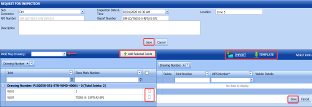
Figure 5.29: REQUEST FOR INSPECTION page
 Tip: A report number and an RFI number for a new RFI weld VI request will be updated automatically in the Report Number and the RFI Number boxes, respectively.
 -
In the Sub Contractor box, select the name of a sub-contractor from a drop-down list.
-
In the Inspection Date & Time box, select the date of inspection.
-
In the Location box, enter the location detail.
-
In the Description box, enter the description for the inspection.
 Note: Before saving the added RFI weld VI request, you must add the details of joints. You can add multiple joints for any added RFI weld VI request by using a box provided in the left side of the REQUEST FOR INSPECTION page. To know how to add joints, see the topic “Add joints for an RFI weld VI request”.
 -
Click Save.


5.29.2 Add Joints for an RFI Weld VI Request
This page shows a list of joints for the corresponding weld map drawing. If you want to add joints for any added RFI weld VI request, do the following,

- In the Weld Map Drawing box, select a weld map drawing number from a drop-down list.
A list of joints including the piece mark numbers opens for the selected weld map drawing.
-
Click the check box of the respective joints.
-
Click
 (Add Selected Joints button).
The selected joints are moved into the Added Joints box located in the right side of the page.

-
To update WPS number and unique number for the added joints, do one of the following steps,
-
-
If you want to update the WPS number for any joint, click the WPS Number column for the respective joint and then select the WPS number from a drop-down list.

-
Enter the unique number for the corresponding joint number in the respective Unique Number column.
 Note: If you want to update the same WPS number of first joint to other joints, click
  (Update WPS No button). The WPS number for the first joint will be updated for other joints.
-
-
- If you want to update the WPS number, unique number, piece mark number details together, do the following,
-
-
Click
 (TEMPLATE button) on the Added Joints box.
An excel worksheet will be downloaded with a pre-defined template. The template contains a list of added joints.

-
Enter the relevant details in the required columns on the excel worksheet.
- Once you have added the WPS, piece mark and other details in the excel worksheet, save the excel worksheet on your computer.
-
Click
 (IMPORT button).
A new window opens for importing the excel worksheet saved on your computer.

-
Click
 (Browse button) to select the excel worksheet to be uploaded.
 -
Select the excel worksheet you want to upload from your computer.
-
Click
 (Upload button) to export the joint details that are included in the excel worksheet.
 The details of the joints in the worksheet will be updated.
-
-
-
Click Save.


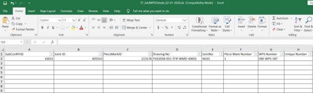

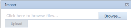


The RFI weld VI request is successfully added.
5.30 View RFI Weld VI (Unique Numbers)
The View RFI Weld VI tab helps you to view and edit the RFI weld VI request, which added by using the RFI Weld VI Request tab. This tab also allows you to add a new RFI weld VI request.
- Click the View RFI Weld VI tab in the Inspection menu.
The REQUEST FOR INSPECTION page opens with a list of added RFI weld VI requests.
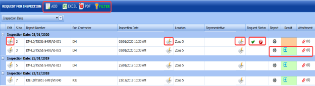
Figure 5.30: REQUEST FOR INSPECTION page

5.30.1 Add an RFI Weld VI Request
If you want to add an RFI weld VI request, do the following,
- Click
 (ADD button) in the REQUEST FOR INSPECTION page.
A new page opens to add an RFI weld VI request. To know how to add an RFI weld VI request, see the topic, “Add an RFI weld VI request”.

Once you have added the RFI weld VI request, you must submit the added request for inspection.
5.30.2 Submit an RFI Weld VI Request
Once you have added the RFI weld VI request, the Request Status column in the REQUEST FOR INSPECTION page is appeared with (Submit and Reject icons). See Fig 5.30.
- If you want to submit the RFI weld VI request, click
 (Submit icon) in the Request Status Otherwise click
  (Reject icon) to reject the request.


5.30.3 Add a Representative for Any RFI Weld VI Request
If you want to add a representative for any added RFI weld VI request,
- Click
 (Edit icon) in the Representative column for the respective RFI weld VI request.
The Edit Form window opens.

-
In the Representative box, enter the name of a representative.
-
Click Save.


5.30.4 Add Result for an RFI Weld VI Request
If you want to add for the added RFI weld VI inspection request, do the following,
- Click
 (Add icon) in the Results column of the REQUEST FOR INSPECTION page, for the respective RFI weld VI request. See Fig 5.30.
A new window opens including the drawing number, joint number and WPS number for the respective RFI weld VI request.
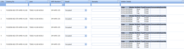
- In the Result column, select the results from a drop-down list based on your inspection.


5.30.5 Print an RFI Weld VI Report
If you want to print an RFI weld VI report, click  (print icon) provided in the Report column of the REQUEST FOR INSPECTION page. See Fig 5.30.
5.30.6 Attach a File into an RFI Weld VI Request
If you want to attach any file with any RFI weld VI request listed in the REQUEST FOR INSPECTION page, follow the procedures given in the topic “Attach a file into a client master drawing” in the Client Master Drawing section.
5.30.7 Edit Any RFI Weld VI Request
If you want to edit any existing RFI weld VI request in the REQUEST FOR INSPECTION page, do the following,
- Click
 (Edit icon) in the Edit column for the respective RFI weld VI request. See Fig 5.30.
The page shows the added details of the RFI weld VI request.
- Click any box where you want to edit the details, and then edit the details in the respective box.
-
Click Save.

5.30.8 Export RFI Weld VI Request List
You can export a list of RFI weld VI request added in the REQUEST FOR INSPECTION page in the pdf and excel formats. To know how to export, see the topic, “Export Areas list” in the Area option.
5.30.9 Filter Any RFI Weld VI Request
If you want to filter any RFI weld VI request from the list of RFI weld VI requests in the REQUEST FOR INSPECTION page, you can use the  (FILTER button). To know how to filter, see the topic, ”Filter Any Area”.
5.31 View AFI Weld VI (Unique Numbers)
The View AFI Weld VI allows you to add a new AFI weld VI request. This tab also helps you to view and edit the added AFI weld VI request.
- Click the View AFI Weld VI tab in the Inspection menu.
The WELD VI INSPECTION REQUEST page opens.
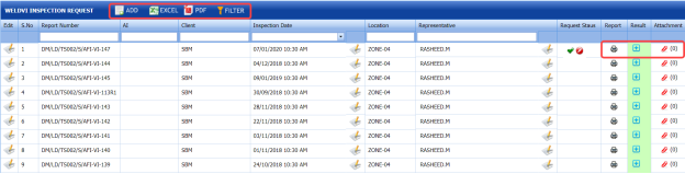
Figure 5.31: WELD VI INSPECTION REQUEST page

5.31.1 Add an AFI Weld VI Request
If you want to add an AFI weld VI request, do the following,
- Click
 (ADD button) in the WELD VI INSPECTION REQUEST page.
The WELD VI - AFI Request page opens to add an AFI weld VI request.

 Tip: A report number and RFI number for a new AFI weld VI request will be updated automatically in the Report Number and RFI Number boxes.
 - In the Representative (AI) box, enter representative name for the application inspection and enter their email id and contact number in the Email and Contact No boxes, respectively.
-
In the Representative (Client) box, enter representative name from the client and enter their email id and contact number in the Email and Contact No boxes, respectively.
-
In the Inspection Date box, select the date of inspection.
- In the Representative (Contractor) box, enter representative name from the contractor and enter their email id and contact number in the Email and Contact No boxes, respectively.
-
In the Activity Code As Per ITP box, select the activity code as per ITP from a drop-down list.
- In the Activity Code As Per Client box, select the activity code as per client from a drop-down list.
-
In the Examination Area box, enter the detail of examination area.
-
In the Viewing Condition box, enter the viewing condition detail.
-
In the Project Specification box, enter the project specification detail.
-
In the Instrument box, select an instrument from a drop-down list.
-
In the Surface Condition box, enter the surface condition detail.
-
In the Location box, enter the location detail.
- In the Description/ Code Acceptance box, enter the description or the code acceptance detail for the inspection.
- In the Inspection Item/ Technique Used box, enter the details of items to be inspected or used technique detail.
-
In the Subject Coverage/ Object box, enter the subject coverage or object detail.
-
In the Comments box, enter your comments if any.
 Note: Before saving the added AFI weld VI request, you must add the details of joints. You can add multiple joints for any added weld VI request by using a box provided in the left side of the page. To know how to add joints, see the topic “Add joints for an AFI fit up request”.
 -
Click Save.

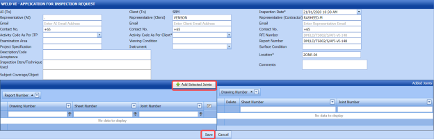


5.31.2 Add Joints for an AFI Weld VI Request
If you want to add joints for any added AFI weld VI request, do the following,
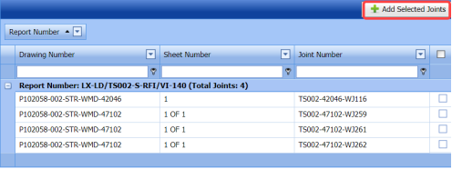
Once you enter the details to add an AFI weld VI request, a list of joints including the joint numbers, sheet numbers, and drawing numbers opens.
- Click the check box of the respective joints.
- Click
 (Add Selected Joints button).
The selected joints are moved into the Added Joints box located in the right side of the page.

-
Click Save.

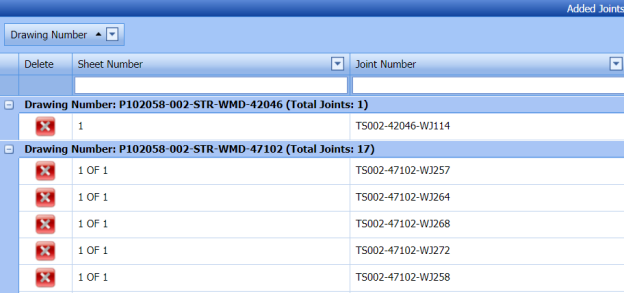
The selected joints are successfully added for the AFI weld VI request.
The AFI weld VI request is successfully added. Once you have added the AFI weld VI request, you must submit the added weld VI request for inspection.
5.31.3 Submit an AFI Weld VI Request
Once you have added the AFI weld VI request, the Request Status column in the WELD VI INSPECTION REQUEST page is appeared with (Submit and Reject icons). See Fig 5.31.
- If you want to submit the RFI weld VI request, click
 (Submit icon) in the Request Status column. Otherwise click
 (Reject icon) to reject the request.


5.31.4 Change a Representative for Any AFI Weld VI Request
If you want to change a representative for any added AFI weld VI request,
- Click
 (Edit icon) in the Representative column for the respective AFI weld VI request.
The Edit Form window opens.
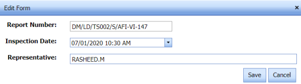
-
In the Representative box, enter the name of a representative.
-
Click Save.


5.31.5 Add Result for an AFI Weld VI Request
If you want to add result for the added AFI weld VI inspection request, do the following,
- Click
 (Add icon) in the Results column of the WELD VI INSPECTION REQUEST page, for the respective AFI weld VI request. See Fig 5.31.
A new window opens including the drawing number and joint number for the respective AFI weld VI request.

-
In the Result column, select the results from a drop-down list based on your inspection.
-
Click Save.

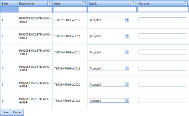
5.31.6 Print an AFI Weld VI Report
If you want to print an AFI weld VI report, click (print icon) provided in the Report column of the WELD VI INSPECTION REQUEST page. See Fig 5.31.
5.31.7 Attach a File into an AFI Weld VI Request
If you want to attach any file with any AFI weld VI request listed in the WELD VI INSPECTION REQUEST page, follow the procedures given in the topic “Attach a file into a client master drawing” in the Client Master Drawing section.
5.31.8 Edit Any AFI Weld VI Request
If you want to edit any existing AFI weld VI request in the WELD VI INSPECTION REQUEST page, do the following,
- Click
 (Edit icon) in the Edit column for the respective AFI weld VI request. See Fig 5.31.
The page shows the added details of the AFI weld VI request.
- Click any box where you want to edit the details, and then edit the details in the respective box.
-
Click Save.

5.31.9 Export AFI weld VI Request List
You can export a list of AFI weld VI request added in the WELD VI INSPECTION REQUEST page in the pdf and excel formats. To know how to export, see the topic, “Export Areas list” in the Area option.
5.31.10 Filter Any AFI Weld VI Request
If you want to filter any AFI weld VI request from the list of AFI weld VI requests in the WELD VI INSPECTION REQUEST page, you can use the  (FILTER button). To know how to filter, see the topic, ”Filter Any Area”.
5.32 Dust Level
Dust level test is performed to check the dust level. The Dust Level tab in the Inspection menu used to perform the dust level in the Structural project.
- Click Dust Level in the Inspection menu.
The Dust Level page opens.
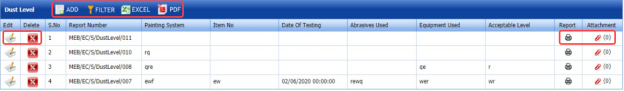
Figure 5.32: Dust Level page

5.32.1 Add a Dust Level
If you want to add a dust level,
- Click
 (ADD button) in the Dust Level See Fig 5.32.
The page shows a new window to add the details of the dust level.

-
In the Painting System box, enter the painting system name.
-
In the Item No box, enter the item number.
-
In the Date of Testing box, select the dust level testing date.
-
In the Abrasives Used box, enter the detail of abrasives used in the dust level testing.
-
In the Equipment Used box, enter the detail of equipment used in the dust level testing.
-
In the Acceptable Level box, enter the acceptable level detail.
-
Click Save.
The added dust level test will be listed in the Dust Level page.

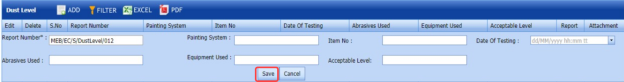
5.32.2 Edit a Dust Level
If you want to edit any existing dust level in the Dust Level page,
- Click
 (Edit icon) of the respective dust level. See Fig 5.32.
The Dust Level page shows the details of the selected dust level.
-
Edit the details where you want.
-
Click Save.

5.32.3 Delete a Dust Level
If you want to delete any existing dust level in the Dust Level page, you can use  (Delete icon) provided in the Dust Level page. To know how to delete, see the topic, “Delete Any Area”.
5.32.4 Attach a File into a Dust Level
If you want to attach any file with any dust level listed in the Dust Level page, follow the procedures given in the topic “Attach a file into a client master drawing” in the Client Master Drawing section.
5.32.5 Print a Dust Level Report
If you want to print a dust level report, click (print icon) provided in the Report column of the Dust Level page. See Fig 5.32.
5.32.6 Export Dust Level List
You can export a list of dust levels added in the Dust Level page in both the pdf and excel formats by using  (PDF button) and
  (Excel button). To know how to export, see the topic, “Export Areas list” in the Area option.
5.32.7 Filter Any Dust Level
If you want to filter any specific dust level, you can use  (FILTER button) located on the Dust Level page. To know how to filter, see the topic, ”Filter Any Area”.
5.33 Blotter Test
Blotter test is used to check the cleanliness of the compressed air, where the compressed air free from any form of contaminants is necessary before its usage. The Blotter Test tab in the Inspection menu helps you to add the results of blotter test.
- Click Blotter Test in the Inspection menu.
The Blotter Test page opens.

Figure 5.33: Blotter Test page
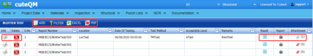
5.33.1 Add a Blotter Test Report
If you want to add a blotter test report, do the following steps,
- Click
 (ADD button) in the Blotter Test page.
The page shows a new window to add the details of the blotter test report.

-
In the Location box, enter the location name.
-
In the Date of Testing box, select the date of blotter test.
-
In the Test Method box, enter the test method detail.
-
In the Acceptable Level box, enter the acceptable level detail.
-
In the Remarks box, enter your remarks if any.
-
Click Save.

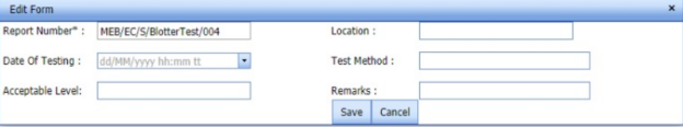
The blotter test report will be added and listed in the Blotter Test page. Once you have added the blotter test report, you must add the results of blotter test.
5.33.2 Add Results of Blotter Test
After completing the blotter test, you can add the blotter test result details. To add results, do the following steps,
- Click
 (Add icon) in the Results column of the respective report.
The Result window opens with the test readings.
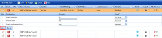
-
In the Result column, select the result of each test reading from the given result options in the drop-down list.
-
In the Remarks column, enter your remarks if any.
-
Click Save.

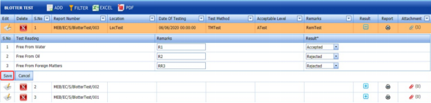
5.33.3 Edit Any Blotter Test Report
If you want to edit any existing blotter test report in the Blotter Test page, do the following,
- Click
 (Edit icon) in the Edit column for the respective blotter test report. See Fig 5.33.
The Blotter Test page opens with the details of the selected blotter test report.
- Click any box where you want to edit the details, and then edit the details in the respective box.
-
Click Save.

5.33.4 View a Blotter Test Report
If you want to view a blotter test report, click (print icon) provided in the Print column of the Blotter Test page. See Fig 5.33.
5.33.5 Attach a File into a Blotter Test Report
If you want to attach a file with any existing blotter test report listed in the Blotter Test page, you can attach the file by using  (Attach icon) in the Attachment column. To know how to attach, follow the procedures given in the topic “Attach a file into a client master drawing”.
5.33.6 Export Blotter Test Report List
You can export a list of blotter test report list added in the Blotter Test page in both the pdf and excel formats by using (PDF button) and (Excel button). To know how to export, see the topic, “Export Areas list”.
5.33.7 Filter Any Blotter Test Report
If you want to filter any specific blotter test report in the Blotter Test page, you can use  (FILTER button) located on the Blotter Test page. To know how to filter, see the topic, ”Filter Any Area”.
5.34 Fairing Report
The Fairing Report tab in the Inspection menu helps you to add the results of fairing test.
- Click Fairing Report in the Inspection menu.
The Fairing Report page opens.
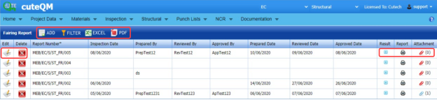
Figure 5.34: Fairing Report page

5.34.1 Add a Fairing Report
If you want to add a fairing report, do the following steps,
- Click
 (ADD button) in the Fairing Report page.
The page shows a new window to add the details of the fairing report.

- In the Inspection Date box, select the date of inspection.
-
In the Prepared By box, enter the name of a person who has prepared the fairing report.
- In the Prepared Date box, select the prepared date of the fairing report.
-
In the Reviewed By box, enter the name of a person who has reviewed the fairing report.
-
In the Reviewed Date box, select the reviewed date of the fairing report.
-
In the Approved By box, enter the name of a person who has approved the fairing report.
-
In the Approved Date box, select the approved date of the fairing report.
-
Click Save.

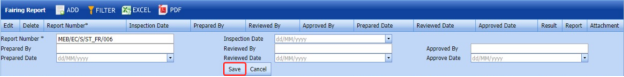
The fairing report will be added and listed in the Fairing Report page. Once you have added the fairing report, you must add the results of fairing test.
5.34.2 Add Results of Fairing Test
After completing the fairing test, you can add the fairing test result details. To add results, do the following steps,
- Click
 (Add icon) in the Results column of the respective report.
The Fairing Request Details window opens.
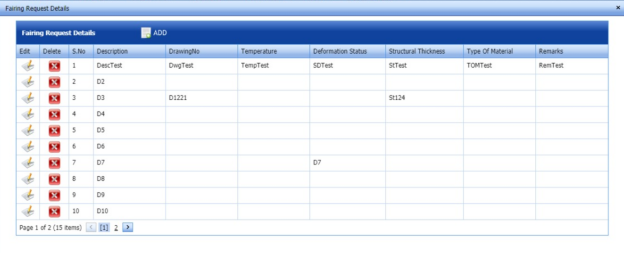
-
Click
 (ADD button) in the Fairing Request Details window.
-
In the Description box, enter the description for the fairing test.
-
In the Drawing No box, enter the drawing number.
-
In the Temperature box, enter the temperature value.
-
In the Deformation Status box, enter the deformation status detail.
-
In the Structural Thickness box, enter the structural thickness value.
-
In the Structural Thickness box, enter the structural thickness value.
-
In the Type of Material box, enter the type of material.
-
Click Save.


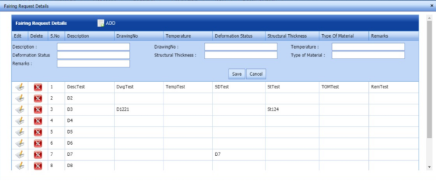
5.34.3 Edit Any Fairing Report
If you want to edit any existing fairing report in the Fairing Report page, do the following,
- Click
 (Edit icon) in the Edit column for the respective fairing report. See Fig 5.34.
The Fairing Report page opens with the details of the selected fairing report.
-
Click any box where you want to edit the details, and then edit the details in the respective box.
-
Click Save.

5.34.4 View a Fairing Report
If you want to view a fairing report, click  (print icon) provided in the Print column of the Fairing Report page. See Fig 5.34.
5.34.5 Attach a File into a Fairing Report
If you want to attach a file with any existing fairing report listed in the Fairing Report page, you can attach the file by using (Attach icon) in the Attachment column. To know how to attach, follow the procedures given in the topic “Attach a file into a client master drawing”.
5.34.6 Export Fairing Report List
You can export a list of fairing report list added in the Fairing Report page in both the pdf and excel formats by using  (PDF button) and
  (Excel button). To know how to export, see the topic, “Export Areas list”.
5.34.7 Filter Any Fairing Report
If you want to filter any specific fairing report in the Fairing Report page, you can use  (FILTER button) located on the Fairing Report page. To know how to filter, see the topic, ”Filter Any Area”.
5.35 Chloride Test
The Chloride Test tab in the Inspection menu helps you to add the results of chloride test.
- Click Chloride Test in the Inspection menu.
The Chloride Test page opens.
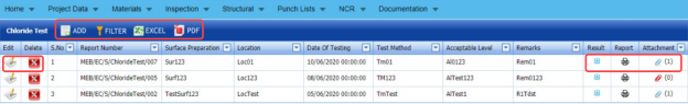
Figure 5.35: Chloride Test page

5.35.1 Add a Chloride Test Report
If you want to add a chloride test report, do the following steps,
- Click
 (ADD button) in the Chloride Test page.
The page shows a new window to add the details of the chloride test report.
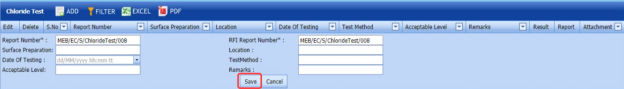
-
In the Surface Preparation box, enter the surface preparation detail.
-
In the Location box, enter the location detail.
-
In the Date of Testing box, select the date of chloride test.
-
In the Test Method box, enter the test method detail.
-
In the Acceptance Level box, enter the acceptance level detail.
-
In the Remarks box, enter your remarks if any.
-
Click Save.


The chloride test report will be added and listed in the Chloride Test page. Once you have added the chloride test report, you must add the results of chloride test.
5.35.2 Add Results of Chloride Test
After completing the chloride test, you can add the chloride test result details. To add results, do the following steps,
- Click
 (Add icon) in the Results column of the respective report.
The Chloride Request Details window opens.
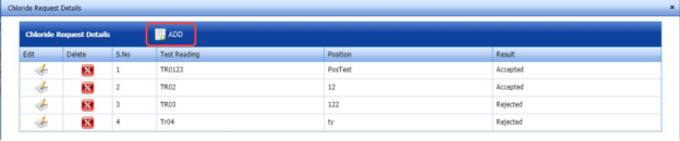
-
Click
 ADD button) in the Chloride Request Details window.
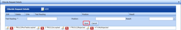
-
In the Test Reading box, enter the test reading detail.
-
In the Position box, enter the position detail.
-
In the Result box, select the result of the chloride test.
-
Click Save.


5.35.3 Edit Any Chloride Test Report
If you want to edit any existing chloride test report in the Chloride Test page, do the following,
- Click
 (Edit icon) in the Edit column for the respective chloride test report. See Fig 5.35.
The Chloride Test page opens with the details of the selected chloride test report.
-
Click any box where you want to edit the details, and then edit the details in the respective box.
-
Click Save.

5.35.4 View a Chloride Test Report
If you want to view a chloride test report, click  (print icon) provided in the Print column of the Chloride Test page. See Fig 5.34.
5.35.5 Attach a File into a Chloride Test Report
If you want to attach a file with any existing chloride test report listed in the Chloride Test page, you can attach the file by using  (Attach icon) in the Attachment column. To know how to attach, follow the procedures given in the topic “Attach a file into a client master drawing”.
5.35.6 Export Chloride Test Report List
You can export a list of chloride test report list added in the Chloride Test page in both the pdf and excel formats by using  (PDF button) and
  (Excel button). To know how to export, see the topic, “Export Areas list”.
5.35.7 Filter Any Chloride Test Report
If you want to filter any specific chloride test report in the Chloride Test page, you can use  (FILTER button) located on the Chloride Test page. To know how to filter, see the topic, ”Filter Any Area”.
5.36 Inspection Requisition Summary Report
The Inspection Requisition Summary tab in the Inspection menu used to view the inspection requisition summary report for a particular period.
- Click Inspection Requisition Summary in the Inspection menu.
The Requisition Inspection Summary page opens.
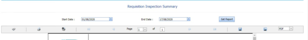
Figure 5.36: Requisition Inspection Summary page
-
In the Start Date and End Date boxes, select the start and end dates.
-
Click Get Report.
The inspection requisition summary report for the selected period will be opened.

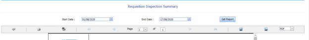
5.36.1 Print an Inspection Requisition Summary Report
If you want to print an inspection requisition summary report, use  and
and  (print icons) provided in the Requisition Inspection Summary page.
-
If you want to print the current page of the inspection requisition summary report, click
 (print icon including the page number).
 -
If you want to print all the pages of the inspection requisition summary report, click
 (print icon).


5.36.2 Export an Inspection Requisition Summary Report
You can export the inspection requisition summary report in various formats by using the option  provided in the upper right corner of the Requisition Inspection Summary page.
No Comments