Piping
- User Management
- Home
- Project Data
- Materials
- Inspection
- Piping
- Test Pack (ISO)
- Punch Lists
- Documentation
User Management
1.1 Login
To login into the cuteQM app,
- Open your web browser.
- Type the URL provided by your administrator, in the address bar of your web browser.
The login page appears.
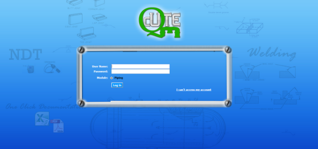
- In the login page, enter your user name and password in the respective boxes.
 Note: If you forgot your password, click “I can’t access my account”. You will be redirected into a new web page. Enter your username to receive your password.


- In the Module section, select Piping.
- Click Login.
Once you have successfully logged in into the cuteQM app, the home page of the cuteQM app opens.
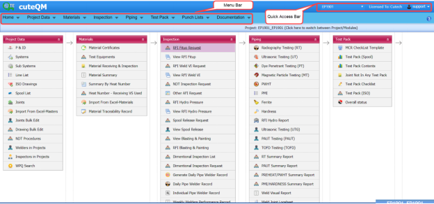
Figure 4.1 Home page of cuteQM app
 Note: The user name you have entered, the project you have been assigned, and the module you have selected are displayed in the upper right corner of the home page.
1.2 My Profile
If you want to upload digital signature ,
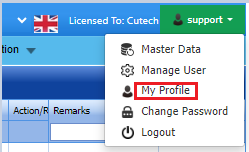
- Click your user name displayed on the quick access bar of the home page. See Fig 1.1.
A drop-down list opens with multiple options.
- Click My Profile option
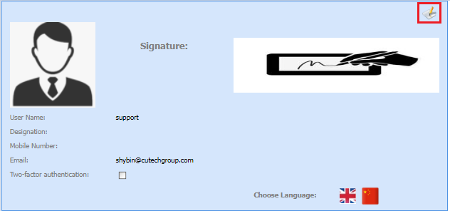
4.Click file upload icon as shown below
5.Upload the signature from device
7.Click Update button.
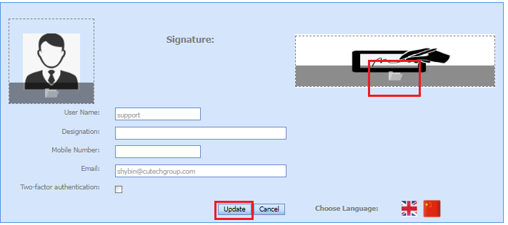
My profile updated successfully.
1.3 Change Password
If you want to change your current password,
- Click your user name displayed on the quick access bar of the home page. See Fig 1.1.
A drop-down list opens with multiple options.

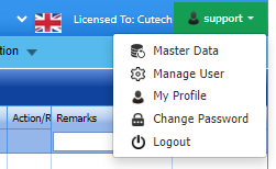
- Click the Change Password option.
The Change Password page opens.

 Note: Before changing your password read the conditions specified in the Change Password page.
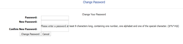

- In the Password box, enter your current password.
- In the New Password box, enter your new password.
- In the Confirm New Password box, enter your new password again.
- Click Change Password.
Your password will be successfully changed.
1.4 Log Out
If you want to log out from the app,
- Click your user name displayed on the quick access bar of the home page. See Fig 1.1.
A drop-down list opens with multiple options.
- Click Log out.
Your current session ends now. The home page appears.
Home
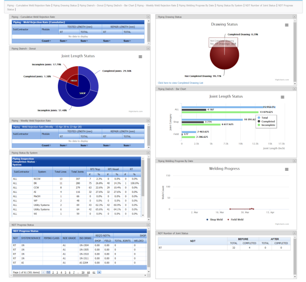
2.1 Dashboard
The Dashboard tab in the Home menu displays graphs, charts, and tables, which helps you to monitor and track the summary reports of various inspection and welding progress in the piping module.
 Note: The dashboard displayed on the app is linked to a database that allows the report to be constantly updated.
The Dashboard page shows the following graphs, charts, and tables:
- Piping – Weld Rejection Rate (Cumulative)
- Piping Drawing Status
- Piping – Weekly Weld Rejection Rate
- Piping Dia Inch
- Piping Status by System
- Piping Welding Progress by Date
- NDT Progress Status
- NDT Number of Joint Status
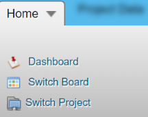
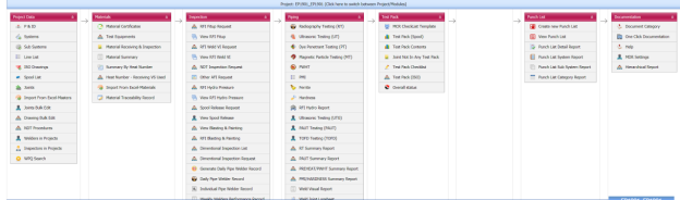
2.2 Switch Board
The Switch Board tab in the Home menu show the consolidated view of various tabs listed in multiple menus in the menu bar.
Once you have successfully logged in into the cuteQM app, you can view the Home Page. In the Home Page, the menu bar appears with multiple menus, otherwise you can select the Switch Board tab to view all the menus.
To select the Switch Board tab,
The Switch Board tab includes multiple options such as Project Data, Materials, Inspection, Piping, Test Pack, Punch List, and Documentation.
2.3 Switch Project
The Switch Project tab in the Home menu helps you to add a new project/module and switch between various projects and modules added in the app.
2.3.1 Switch between Various Projects and Modules
The switch project window opens with a list of projects and modules that are already added in the web.

Figure 5.1: Switch project window
3. If you want to switch between various projects and modules,
- Select a project you want from multiple projects listed in the left side of the window.
Once you have selected the project, a list of modules related to the project is displayed.
-
Select a module you want from multiple modules listed in the right side of the window.
4. Click Select.
2.3.2 Add a New Project
If you want to add a new project, do the following
|
If you want to add a new project, you must have been assigned as an administrator or a power user otherwise you cannot add any new project. |
- Click New Skid/ Module. See Fig 2.1.
The add project/module page opens with two options such as Projects and Skid/ Module.
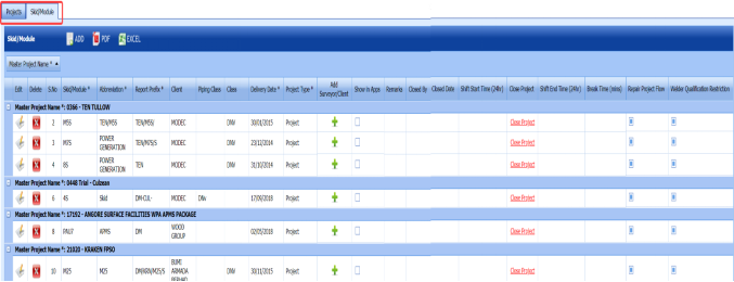
Figure 2.2: Add project/module page
2. Click Projects.
The Projects page opens.
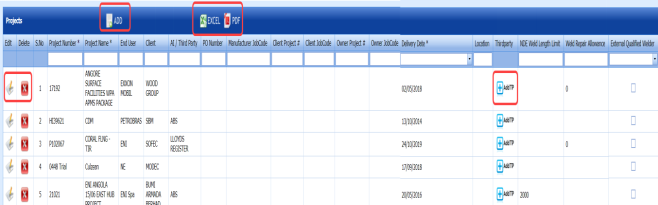
Figure 2.3: Projects page
3. Click  (ADD button) in the upper side of the Projects page.
A new window opens to add a new project.
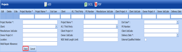
 Note: The fields notified with a symbol (*) are mandatory. You must enter the relevant details in that fields before saving.
- In the Project Number box, enter the project number.
- In the Project Name box, enter a project name.
-
In the End User box, select an end user from a drop-down list.
- In the Client box, select a client from a drop-down list.
- In the AI/ Third Party box, select an AI or a third party from a drop-down list.
 Note: If you want to add multiple third parties, add third parties by clicking
 (Add TP button) in the Third party column of the Projects page.
 - In the Purchase Order (PO) Number box, enter the PO number.
- In the Manufacturer Job Code box, enter the manufacturer job code number.
- In the Client Project box, enter the client project code.
- In the Client Job Code box, enter the client job code.
- In the Owner Project box, enter the owner project code.
- In the Owner Job Code box, enter the owner job code.
- In the Delivery Date box, choose the delivery date.
- In the Location box, enter the location detail.
- In the Non-Destructive Examination (NDE) Weld Length Limit box, enter the length limit of NDE welding.
- If you need an external qualified welder, click the check box provided with the External Qualified Welder option.
- In the Weld Repair Allowance box, enter the amount for weld repair.


4. Click Save.
A new project is added successfully.
2.3.3 Edit a Project
If you want to edit any existing project details from the list of projects in the Projects page, do the following,
1. Click  (Edit icon) in the Edit column for the respective project. See Fig 2.3.
A new window opens to edit the project.
2. Click any box where you want to edit the details, and then edit the details in the respective box in the Projects page.
3. Click Save.
2.3.4 Delete a Project.
If you want to delete any specific project from the list of projects, you can use (Delete icon) provided in the Delete column of the Projects page, See Fig 2.3.
1. Click  (Delete icon) for the corresponding project.
You receive a notification message “Do you want to delete this row?”.
2. Click OK.
2.3.5 Export Projects List
You can export a list of projects in the pdf and excel formats.
- If you want to export the projects list in the pdf format, click
 (PDF button). See Fig 2.3.
The project list will be downloaded in the pdf format.
-
If you want to export the projects list in the excel format, click
 (Excel button).
 The project list will be downloaded in the excel format.


2.3.6 Add a New Module
If you want to add a new module, do the following
|
If you want to add a new module, you must have been assigned as an administrator or a power user otherwise you cannot add any new module. |
- Click New Skid/ Module. See Fig 2.1. The add project/module page opens with two options such as Projects and Skid/ Module. See Fig 2.2.
- Click Skid/Module.
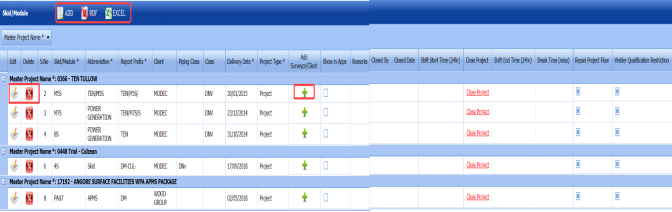
The Skid/Module page opens.
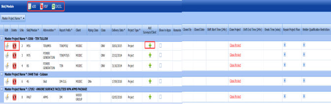
Figure 5.3.1: Skid/Module page
-
Click
 (ADD button) in the upper side of the Skid/Module page.
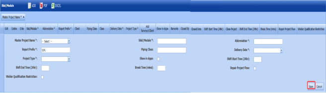
The skid/module box opens to add a new module.
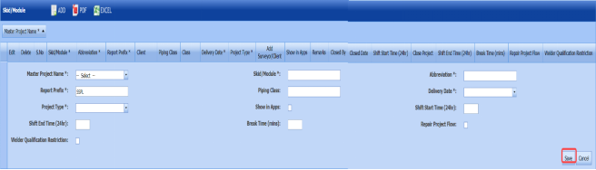
 Note: The fields notified with a symbol (*) are mandatory. You must enter the relevant details in that fields before saving.
-
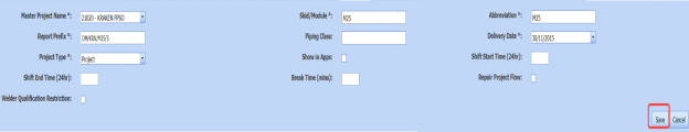
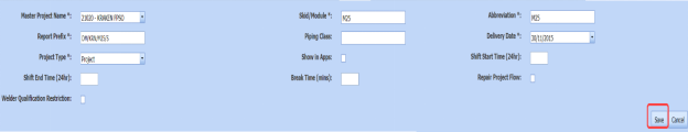
- In the Master Project Name box, enter the master project name from a drop-down list.
- In the Skid/Module box, enter a module name.
- In the Abbreviation box, enter the abbreviation for the added module.
- In the Report Prefix box, the report prefix will be entered automatically. If you want change, you can edit the report prefix.
- In the Piping Class box, enter the piping class name.
- In the Delivery Date box, choose the delivery date.
- In the Project Type box, select the type of project from a drop-down list.
-
If you want to show this module in the cuteQM mobile app, click the check box provided with the Show in Apps option.
- In the Shift Start Time (24hr)box, enter the shift starting time.
- In the Shift End Time (24hr)box, enter the shift ending time.
- In the Break Time (mins)box, enter the break time duration.
- If you want to enable the repair project flow option, select the check box provided with the Repair Project Flow column.
- If you want to enable the welder qualification restriction option, select the check box provided with the Welder Qualification Restriction column.
- Click Save.
A new module is added successfully.
-


2.3.7 Add a Surveyor, a Client or Other Role for Module
If you want to add a surveyor, a client or other role for any added module,
-
Click a respective
 (Add icon) provided in the Add Surveyor/Client column. The Add Surveyor/Client/Others window opens.
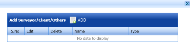
-
Click
 (ADD button). A new window opens to enter the name and type of a role.
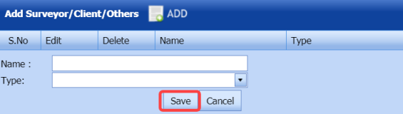
-
In the Name box, enter the name of the person to whom you want to add a role.
-
In the Type box, select the type of role from a drop-down list.
- Click Save.


2.3.8 Edit a Module
If you want to edit any existing module details from the list of modules in the Skid/Module page, do the following,
-
Click
 (Edit icon) in the Edit column for the respective module. See Fig 2.3.1.
 A new window opens to edit the module.
- Click any box where you want to edit the details, and then edit the details in the respective box in the Skid/Module page.
-
Click Save.

2.3.9 Delete a Module
If you want to delete any specific module from the list of modules, you can use  (Delete icon) provided in the Delete column of the Skid/Module page, See Fig 2.3.1.
-
Click
 (Delete icon) for the corresponding module.
 You receive a notification message “Do you want to delete?”.
-
Click OK.

2.3.10 Export Modules List
You can export a list of modules added in the Skid/Module page in the pdf and excel formats.
- If you want to export the modules list in the pdf format, click
 (PDF button). See Fig 2.3.1.
 The modules list will be downloaded in the pdf format.
-
If you want to export the modules list in the excel format, click

(Excel button).
The modules list will be downloaded in the excel format.


2.3.11 Close a Project
If you want to close any project from the app, do the following
|
Make sure that once you have closed any project, you cannot even open or access the closed project. |
- Click Close Project in the Close Project column for the corresponding module and project type. See Fig 2.3.1.
You receive a notification message “Are you sure want to close this project? You will not be able to access/reopen this project again”.
-
Click OK to close the project.
Project Data
3.0 Project Data
The Project Data menu in the cuteQM app helps you to add the master data and the personal data for the piping project. Once you click the Project Data menu, the following tabs open,
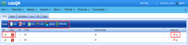
3.1 Piping and Instrumentation Diagram (P&ID)
P&ID is a schematic diagram which shows the functional relationship of piping, instrumentation, and system equipment components. The P&ID includes mechanical equipment with names and numbers, Process piping, sizes and identification, Flow directions, and so on.
The P&ID tab in the Project Data menu helps you to add a P&ID. If you want to navigate to P&ID, do the following,
- Click P&ID in the Project Data menu.
The P&ID page opens.

Figure 3.1: P&ID page
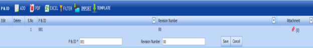
3.1.1 Add a P&ID
If you want to add a new P&ID, do the following steps,
-
Click
 (ADD button) in the P&ID page. See Fig 3.1.
 A new window opens to add a new P&ID.
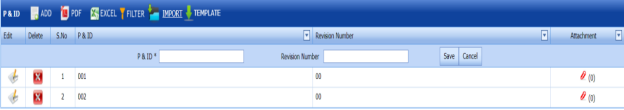
 Note: The field notified with a symbol (*) is mandatory. You must enter the relevant details in that fields before saving.
 -
In the P&ID box, enter the P&ID number.
-
In the Revision Number box, enter the revision number for the P&ID.
- Click Save.
The P&ID is successfully added and listed in the P&ID page.


3.1.2 Edit a P&ID
If you want to edit any existing P&ID in the P&ID page,
- Click
 (Edit icon) of the respective P&ID. See Fig 3.1.
 - The P&ID page shows the details of the P&ID.

- Edit the details where you want.
- Click Save.

3.1.3 Delete a P&ID
If you want to delete any existing P&ID in the P&ID page,
-
Click
 (Delete icon) of the respective P&ID. See Fig 3.1.
 You receive a notification message “Confirm Delete?”.
-
Click OK.
The selected P&ID will be deleted from the P&ID page.

3.1.4 Export P&ID list
You can export a list of P&IDs added in the P&ID page in both the pdf and excel formats.
-
If you want to export the P&ID list in the pdf format, click
 (PDF button).
 The P&ID list will be downloaded as a pdf file.
-
If you want to export the P&ID list in the excel format, click
 (Excel button).
 The P&ID list will be downloaded as an excel file.


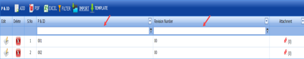
3.1.5 Filter a P&ID
If you want to filter any specific P&ID in the P&ID page, do the following,
-
Click
 (FILTER button) located on the P&ID See Fig 3.1.
Once you clicked the Filter button, the filter box opens for the P&ID and Revision Number columns.

-
Enter relevant detail in the respective column’s filter box to filter any P&ID.

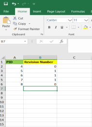
3.1.6 Import Multiple P&IDs
If you want to import multiple P&IDs together, do the following,
-
Click
 (TEMPLATE button). See Fig 3.1.
An excel worksheet will be downloaded with a predefined template to enter the details of P&IDs.
-
Enter the required P&ID details in the respective columns of the excel worksheet.
- Once you have added the P&ID details in the excel worksheet, save the excel worksheet on your computer.
-
Click
 (IMPORT button). See Fig 3.1.
 A new window opens for importing the excel worksheet saved on your computer.

-
Click
 (Browse button) to select the excel worksheet to be uploaded.
 -
Select the excel worksheet you want to upload from your computer.
-
Click
 (Upload button) to export the P&IDs that are included in the excel worksheet.
 The details of the P&IDs in the worksheet will be displayed in the P&ID page.


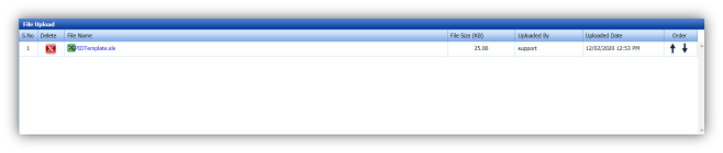
3.1.7 Attach a File into a P&ID
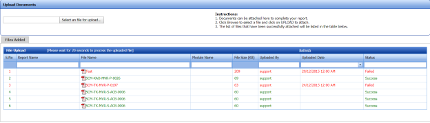
If you want to attach a file for example drawing, with any existing P&ID listed in the P&ID page,
-
Click
 (Attach icon) provided against the respective P&ID in the P&ID page.
The File Upload (P&ID - Drawings) page opens.
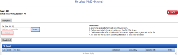
 Note: Before uploading any file, read the instructions given in the File Upload (P&ID - Drawings) page.
 -
Click
 (Browse button).
 - Select a file which you want to upload from your computer.
-
Click
 (Upload button) to attach the file.
The uploaded file will be displayed in the File Upload table.


3.2 System
You can add the details of systems to be used in the piping project by using the Systems tab in the Project Data menu. If you want to navigate to Systems,
-
Click Systems in the Project Data menu.
The System page opens.
Figure 3.2: System page
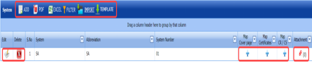
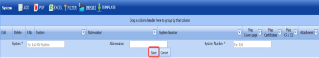
3.2.1 Add a System
If you want to add a new system, do the following steps,
-
Click
 (ADD button) in the System See Fig 3.2.
A new window opens to add a new system.

 Note: The fields notified with a symbol (*) are mandatory. You must enter the relevant details in that fields before saving.
 - In the System box, enter the system name.
- In the Abbreviation box, enter the abbreviation for the system name.
-
In the System Number box, enter the system number.
- Click Save.
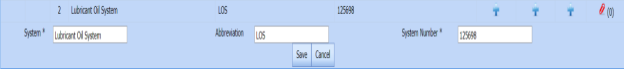
The system is successfully added and listed in the System page.
 Note:
Note: -
-
If you want to map cover page for any added system, click the respective
 (Add icon)
 provided in the Map Cover Page column and add the cover pages.
-
If you want to map certificates for any added system, click the respective
 (Add icon)
provided in the Map Certificates column and add the cover pages.
-
If you want to map Check Record/Check Sheet (CR/CS) for any added system,
click the respective
 (Add icon) provided in the Map CR/CS column and add the cover pages.
-
-


3.2.2 Edit a System
If you want to edit any existing system in the System page,
-
Click
 (Edit icon) of the respective System. See Fig 3.2.
The System page shows the details of the selected system.

-
Edit the details where you want.
-
Click Save.

3.2.3 Delete a System
If you want to delete any existing system in the System page, you can use (Delete icon) provided in the System page. To know how to delete, see the topic, “Delete P&ID”.
3.2.4 Export System List
You can export a list of systems added in the System page in both the pdf and excel formats by using  (PDF button) and
  (Excel button). To know how to export, see the topic, “Export P&ID list”.
3.2.5 Filter a System
If you want to filter any specific system in the System page, you can use  (FILTER button) located on the System page. To know how to filter, see the topic, “Filter P&ID”.
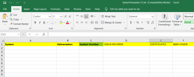
3.2.6 Import Multiple Systems
If you want to import multiple systems together, do the following,
-
Click
 (TEMPLATE button). See Fig 3.2.
An excel worksheet will be downloaded with a predefined template to enter the details of systems.

-
Enter the required system details in the respective columns of the excel worksheet.
-
Once you have added the system details in the excel worksheet, save the excel worksheet on your computer.
-
Click
 (IMPORT button). See Fig 3.2.
A new window opens for importing the excel worksheet saved on your computer.

-
Click
 (Browse button) to select the excel worksheet to be uploaded.
 - Select the excel worksheet you want to upload from your computer.
-
Click
 (Upload button) to export the systems that are included in the excel worksheet.
The details of the systems in the worksheet will be displayed in the System page.


3.2.7 Attach a File into a System
If you want to attach any file with any system listed in the System page, you can attach the file by using (Attach icon) in the Attachment column. To know how to attach, follow the procedures given in the topic “Attach a file into P&ID”.
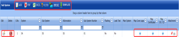
3.3 Sub System
The Sub Systems tab in the Project Data menu helps you to add the details of sub systems to be in used in the piping project. If you want to navigate to Sub Systems,
-
Click Sub Systems in the Project Data menu.
The Sub Systems page opens.

Figure 6.3: Sub System page
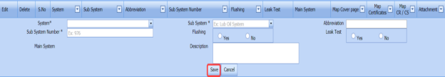
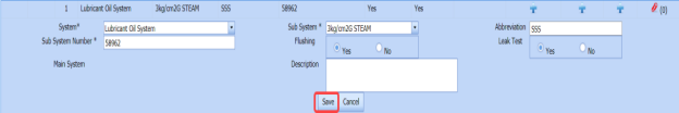
3.3.1 Add a Sub System
If you want to add a new sub system, do the following steps,
-
Click
 (ADD button) in the Sub System See Fig 3.3.
A new window opens to add a new sub system.
 Note: The fields notified with a symbol (*) are mandatory. You must enter the relevant details in that fields before saving.
 - In the System box, select a system from a drop-down list.
- In the Sub System box, select a sub system from a drop-down list.
- In the Abbreviation box, enter the abbreviation for the sub system.
- In the Sub System Number box, enter the sub system number.
-
If the added subsystem needs to be flushed, select Yes in the Flushing option otherwise select No.
- If there is need to perform the leakage test for the added subsystem, select Yes in the Leak Test option otherwise select No.
- In the Description box, enter the description for the added sub system.
- Click Save.
The sub system is successfully added and listed in the Sub System page.


3.3.2 Edit a Sub System
If you want to edit any existing sub system in the Sub System page,
-
Click
 (Edit icon) of the respective sub system. See Fig 3.3.
The Sub System page shows the details of the selected sub system.

- Edit the details where you want.
-
Click Save.

3.3.3 Delete a Sub System
If you want to delete any existing sub system in the Sub System page, you can use  (Delete icon) provided in the Sub System page. To know how to delete, see the topic,
3.3.4 Export Sub System List
You can export a list of sub systems added in the Sub System page in both the pdf and excel formats by using  (PDF button) and
  (Excel button). To know how to export, see the topic, “Export P&ID list”.
3.3.5 Filter a Sub System
If you want to filter any specific sub system in the Sub System page, you can use  (FILTER button) located on the Sub System page. To know how to filter, see the topic, “Filter P&ID”.
3.3.6 Import Multiple Sub Systems
If you want to import multiple sub systems together, do the following,
-
Click
 (TEMPLATE button). See Fig 3.3.
An excel worksheet will be downloaded with a predefined template to enter the details of sub systems.
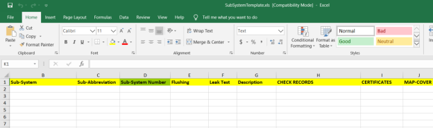
-
Enter the required sub system details in the respective columns of the excel worksheet.
- Once you have added the sub system details in the excel worksheet, save the excel worksheet on your computer.
-
Click
 (IMPORT button). See Fig 3.3.
A new window opens for importing the excel worksheet saved on your computer.

-
Click
 (Browse button) to select the excel worksheet to be uploaded.
 - Select the excel worksheet you want to upload from your computer.
-
Click
 (Upload button)to export the sub systems that are included in the excel worksheet.
 The details of the sub systems in the worksheet will be displayed in the Sub System page.


3.3.7 Attach a File into a Sub System
If you want to attach any file with any sub system listed in the Sub System page, you can attach the file by using  (Attach icon) in the Attachment column. To know how to attach, follow the procedures given in the topic. “Attach a file into P&ID”.
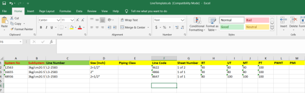
3.4 Lines
The Lines tab in the Project Data menu helps you to add the details of lines to be in used in the piping project. If you want to add Lines,
- Click Lines in the Project Data menu,
The Lines page opens.
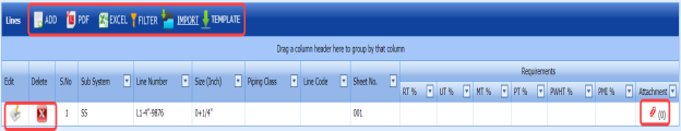
Figure 3.4: Lines page

3.4.1 Add a Line
If you want to add a line, do the following steps,
-
Click
 (ADD button) in the Lines page. See Fig 3.4.
A new window opens to add new lines.
 Note: The fields notified with a symbol (*) are mandatory. You must enter the relevant details in that fields before saving.
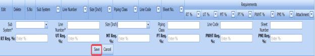
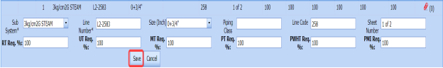
 - In the Sub System box, select a sub system from a drop-down list.
- In the Line Number box, enter the line number.
- In the Size box, select the size of the line.
- In the Piping Class box, enter the piping class name.
- In the Line Code box, enter the line code.
- In the Sheet Number box, enter the sheet number.
- In the RT Req. % box, enter the requirement percentage of RT.
- In the UT Req. % box, enter the requirement percentage of UT.
- In the MT Req. % box, enter the requirement percentage of MT.
- In the PT Req. %box, enter the requirement percentage of PT.
- In the PWHT Req. %box, enter the requirement percentage of PWHT.
- In the PMI Req. %box, enter the requirement percentage of PMI.
 Note: The RT, UT, MT, PT, PWHT, and PMI Requirements (%) should be filled with valid numerical numbers. The joint testing will be performed based on the value given by you, for example, if you enter 100 % of requirement, which means 100 % of the joints will be tested. If you enter 0 %, none of joints will be tested.
 -
Click Save.
The line is successfully added and listed in the Lines page.


3.4.2 Edit a Line
If you want to edit any existing line in the Lines page,
-
Click
 (Edit icon) of the respective sub system. See Fig 3.4.
The Lines page shows the details of the selected line.
-
Edit the details where you want.
-
Click Save.


3.4.3 Delete a Line
If you want to delete any existing line in the Lines page, you can use  (Delete icon) provided in the Lines page. To know how to delete, see the topic, “Delete P&ID”.
3.4.4 Export Line List
You can export a list of lines added in the Lines page in both the pdf and excel formats by using  (PDF button) and
  (Excel button). To know how to export, see the topic “Export P&ID list”.
3.4.5 Filter a Line
If you want to filter any specific line in the Lines page, you can use  (FILTER button) located on the Lines page. To know how to filter, see the topic, “Filter P&ID”.
3.4.6 Import Multiple Lines
If you want to import multiple lines together, do the following,
-
Click
 (TEMPLATE button). See Fig 3.4.
An excel worksheet will be downloaded with a predefined template to enter the details of lines.
- Enter the required line details in the respective columns of the excel worksheet.
-
Once you have added the line details in the excel worksheet, save the excel worksheet on your computer.
-
Click
 (IMPORT button). See Fig 3.4.
A new window opens for importing the excel worksheet saved on your computer.

-
Click
 (Browse button) to select the excel worksheet to be uploaded.
 - Select the excel worksheet you want to upload from your computer.
-
Click
 (Upload button) to export the lines that are included in the excel worksheet.
The details of the lines in the worksheet will be displayed in the Lines page.


3.4.7 Attach a File into a Line
If you want to attach any file with a line listed in the Lines page, you can attach the file by using  (Attach icon) in the Attachment column. To know how to attach, follow the procedures given in the topic “Attach a file into P&ID”.
3.5 Isometric (ISO) Drawings
An isometric drawing is a detailed orthographic drawing that represents the details of 3D structure of the piping system in a 2D format for fabrication of the pipe. If you want to navigate to ISO,
- Click ISO Drawings in the Project Data menu.
The ISO page opens.
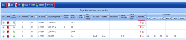
Figure 3.5: ISO page

3.5.1 Add an ISO Drawing
If you want to add a new ISO drawing, do the following steps,
-
Click
 (ADD button) in the ISO page. See Fig 3.5.
 A new window opens to add a new ISO drawing.

 Note: The fields notified with a symbol (*) are mandatory. You must enter the relevant details in that fields before saving.
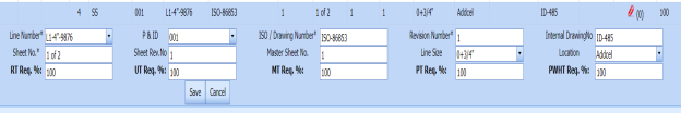
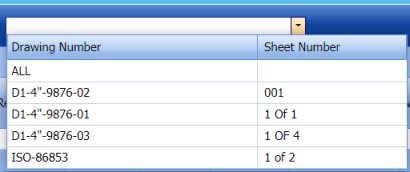
 - In the Line Number box, select the line number from a drop-down list.
- In the P&ID box, select the P&ID from a drop-down list.
- In the ISO Drawing Number box, enter the number for an ISO drawing you want to add.
- In the Revision Number box, enter the revision number for the ISO drawing.
-
In the Internal Drawing No box, enter the internal drawing number of the isometric drawing.
- In the Internal Drawing Rev. No box, enter the revision number for the internal drawing.
- In the Sheet No box, enter the sheet number.
- In the Sheet Rev. No box, enter the sheet revision number.
- In the Master Sheet No box, enter the master sheet number.
- In the Line Size box, select the line size from a drop-down list.
- In the Location box, select the location from a drop-down list.
- In the Sub Contractor box, select the sub-contractor from a drop-down list.
- In the RT Req. % box, enter the requirement percentage of RT.
- In the UT Req. % box, enter the requirement percentage of UT.
- In the MT Req. % box, enter the requirement percentage of MT.
- In the PT Req. % box, enter the requirement percentage of PT.
- In the PWHT Req. % box, enter the requirement percentage of PWHT.
- In the PMI Req. % box, enter the requirement percentage of PMI.
 Note: The RT, UT, MT, PT, PWHT, and PMI Requirements (%) should be filled with valid numerical numbers. The joint testing will be performed based on the value given by you, for example, if you enter 100 % of requirement, which means 100 % of the joints will be tested. If you enter 0 %, none of joints will be tested.
 - Click Save.
The ISO drawing is successfully added and listed in the ISO page.


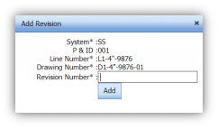
3.5.2 Add Revision for ISO Drawing
Once you have added the ISO drawing, the ISO page shows  (Revision icon) for the added ISO drawing. You can add multiple revisions for the added ISO by using this revision icon.
-
Click
 (Revision icon) of the respective ISO drawing.
The Add Revision box opens.
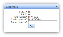
- In the Revision Number box, enter the revision number.
- Click Add.
The revision for the ISO drawing will be added and listed in the ISO page.

3.5.3 Edit an ISO Drawing
If you want to edit any existing ISO drawing in the ISO page,
-
Click
 (Edit icon) of the respective sub system. See Fig 3.5.
The ISO page shows the details of the selected ISO drawing.
- Edit the details where you want.
- Click Save.


3.5.4 Delete an ISO Drawing
If you want to delete any existing ISO drawing in the ISO page, you can use  (Delete icon) provided in the ISO page. To know how to delete, see the topic, “Delete P&ID”.
3.5.5 Export ISO Drawings List
You can export a list of ISO drawings added in the ISO page in both the pdf and excel formats by using  (PDF button) and
  (Excel button). To know how to export, see the topic, “Export P&ID list”.
3.5.6 Filter an ISO Drawing
If you want to filter any specific ISO drawing in the ISO page, you can use  (FILTER button) provided on the ISO page. To know how to filter, see the topic, “Filter P&ID”.
3.5.7 Import Multiple ISO Drawings
If you want to import multiple ISO drawings together, do the following,
-
Click
 (TEMPLATE button). See Fig 3.5.
An excel worksheet will be downloaded with a predefined template to enter the details of ISO drawings.
-
Enter the required ISO drawing details in the respective columns of the excel worksheet.
-
Once you have added the ISO drawing details in the excel worksheet, save the excel worksheet on your computer.
-
Click
 (IMPORT button). See Fig 3.5.
A new window opens for importing the excel worksheet saved on your computer.

-
Click
 (Browse button) to select the excel worksheet to be uploaded.
 - Select the excel worksheet you want to upload from your computer.
-
Click
 (Upload button) to export the ISO drawings that are added in the excel worksheet.
The details of the ISO drawings in the worksheet will be displayed in the ISO page.


3.5.8 Attach a File into an ISO Drawing
If you want to attach any file with an ISO drawing listed in the ISO page, you can attach the file by using  (Attach icon) in the Attachment column. To know how to attach, follow the procedures given in the topic “Attach a file into P&ID”.
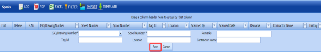
3.6 Spools
A spool refers to a section of a piping system that is pre-fabricated as smaller segments with flanges and fittings. If you want to navigate to Spools,
- Click Spools in the Project Data.
The Spools page opens.
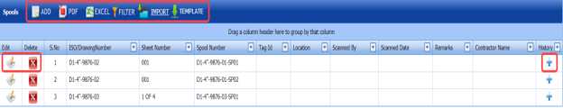
Figure 3.6: Spools page

3.6.1 Add a Spool
If you want to add a new spool, do the following steps,
-
Click
 (ADD button) in the Spools See Fig 3.6.
A new window opens to add a new spool.
 Note: The fields notified with a symbol (*) are mandatory. You must enter the relevant details in that fields before saving.
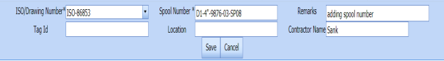
 - In the ISO Drawing Number box, select the ISO drawing number from a drop-down list.
- In the Spool Number box, enter the spool number for a spool you want to add.
- In the Tag Id box, enter the tag id number of the spool.
- In the Location box, select the location from a drop-down list.
- In the Contractor Name box, enter the contractor name.
- In the Remarks box, enter your remarks if any.
- Click Save.
The spool is successfully added and listed in the Spools page.


3.6.2 Edit a Spool
If you want to edit any existing spool in the Spools page,
-
Click
 (Edit icon)of the respective spool. See Fig 3.6.
The Spools page shows the details of the selected spool.
- Edit the details where you want.
- Click Save.


3.6.3 Delete a Spool
If you want to delete any existing spool in the Spools page, you can use  (Delete icon) provided in the Spools page. To know how to delete, see the topic, “Delete P&ID”.
3.6.4 Export Spool List
You can export a list of spools added in the Spools page in both the pdf and excel formats by using  (PDF button) and (Excel button). To know how to export, see the topic, “Export P&ID list”.
3.6.5 Filter a Spool
If you want to filter any spool in the Spools page, you can use  (FILTER button) provided on the Spools page. To know how to filter, see the topic, “Filter P&ID”.
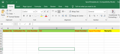
3.6.6 Import Multiple Spools
If you want to import multiple spools together, do the following,
-
Click (TEMPLATE button). See Fig 3.6.
An excel worksheet will be downloaded with a predefined template to enter the details of spools.

-
Enter the required spool details in the respective columns of the excel worksheet.
-
Once you have added the spool details in the excel worksheet, save the excel worksheet on your computer.
-
Click
 (IMPORT button). See Fig 3.6.
A new window opens for importing the excel worksheet saved on your computer.

- Click (Browse button) to select the excel worksheet to be uploaded.
- Select the excel worksheet you want to upload from your computer.
-
Click (Upload button) to export the spool details that are added in the excel worksheet.
The details of the spools in the worksheet will be displayed in the Spools page.


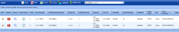
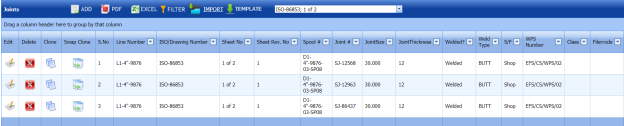
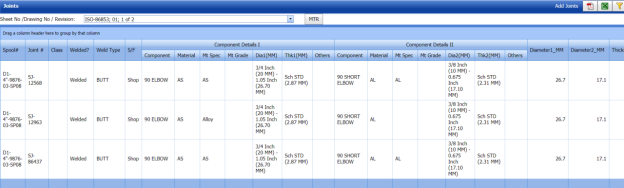
3.7 Joints
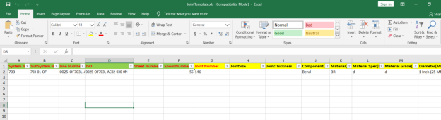
A variety of joints are used in the assembly of pipes. Joints are the points where two or more pieces of materials for example pipes, are joined by welding. The Joints tab in the Project Data menu helps you add the joint details including joint number, material specification, welding type, and so on.
-
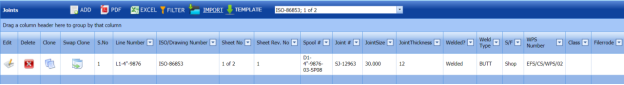
Click Joints in the Project Data menu.
The Joints page opens.
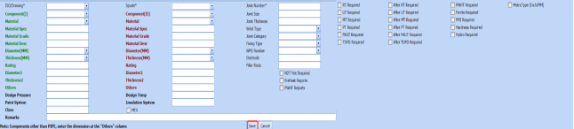
Due to insufficient space, the captured figure of the Joints page is split as four.
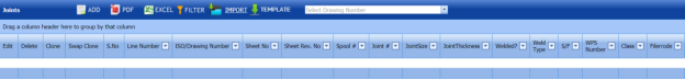
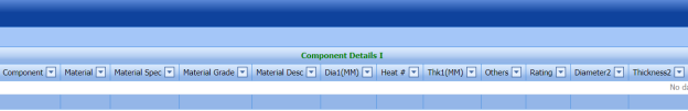
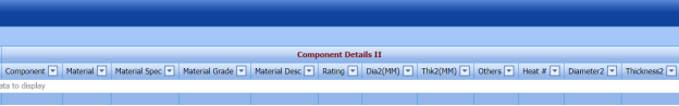
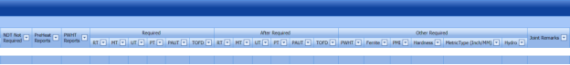
Figure 3.7: Joints page


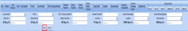
3.7.1 Add a Joint
If you want to add a new joint, do the following steps,
- Click
 (ADD button) in the Joints See Fig 3.7.
A new window opens to add a new joint.
 Note: The fields notified with a symbol (*) are mandatory. You must enter the relevant details in that fields before saving.
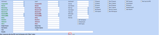
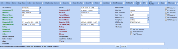
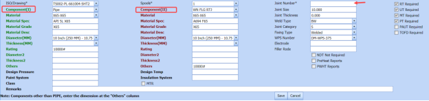
 - In the ISO Drawing Number box, select the ISO drawing number from a drop-down list.
- In the Spools box, select the spool from a drop-down list.
- In the Component (I) box, select the first component which you want to join.
- In the Material box, select the material of the first component.
- Enter the details of first component such as Material Spec, Material Grade, Material Desc, Diameter (MM), Thickness (MM), Rating, Diameter2, and Thickness2.
- In the Component (II) box, select the second component which you want joint.
- In the Material box, select the material of the second component.
- Enter the details of second component such as Material Spec, Material Grade, Material Desc, Diameter (MM), Thickness (MM), Rating, Diameter2, and Thickness2.
- If the component is other than pipe, enter the dimensions in Others
- In the Design Pressure box, enter the design pressure value.
- In the Paint System box, enter the paint system name.
- In the Design Temp box, enter the design temperature value.
- In the Insulation System box, enter the insulation system name.
- In the Joint Number box, enter the joint number.
- In the Joint Size box, enter the joint size range.
- In the Joint Thickness box, enter the joint thickness range.
- In the Weld Type box, select the welding type from a drop-down list.
- In the Joint Category box, select the joint category from a drop-down list.
- In the Fixing Type box, select the fixing type from a drop-down list.
- In the WPS Number box, select the WPS number from a drop-down list.
- In the Electrode box, enter the electrode name.
- In the Filler Rod box, enter the filler rod name.
-
If the NDT inspection is not required for the added joint, select the checkbox of the NDT Not Required option.
-
If the NDT inspection is required for the added joint, select the checkbox of the respective NDT types given for example RT Required, UT Required, and so on.
- In the Remarks box, enter your remarks if any.
- Click Save.
The joint is successfully added.
-
If you want view the added joint, select the respective drawing number from a drop-down list of the Select Drawing Number box in the upper side of the Joints page. and listed in the Joints page.
The joint for the selected drawing number will be displayed in the Joints page.


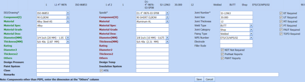
6.7.2 Clone a Joint
The Clone option provided in the Joints page used to add a new joint from previously added joint. If a joint to be added is having the same specifications of any joint already listed in the Joints page, you can add the new joint by using  (Clone icon).
- In the Joints page, find out the joint you want to clone.

-
Click
 (Clone icon) of the respective joint.
The Joints page shows the details of selected joint except joint number in the Joint Number box. See the below figure.
- If you want to change any details, you can change in the respective boxes.
- In the Joint Number box, enter the joint number for the new joint you want to add.
- Click Save.
The new joint is successfully added and listed in the Joints page.


3.7.3 Swap Clone Joint
The Swap Clone option provided in the Joints page used to add a new joint from previously added joint. When you do swap clone of any joint, the first and second components in the joint will be swapped each other.
- In the Joints page, find out the joint you want to swap clone.
- Click
 (Swap Clone icon) of the respective joint.
The Joints page shows the details of selected joint except joint number in the Joint Number box. The Component (I) and Component (II) will be swapped each other. See the below figure.

- If you want to change any details, you can change in the respective boxes.
- In the Joint Number box, enter the joint number for the new joint you want to add.
- Click Save.
The new joint is successfully added and listed in the Joints page.


3.7.4 Edit a Joint
If you want to edit any existing joint in the Joints page,
- Click (Edit icon) of the respective joint. See Fig 3.7.
The Joints page shows the details of the selected joint.

- Edit the details where you want.
- Click Save.
3.7.5 Delete a Joint
If you want to delete any existing joint in the Joints page, you can use  (Delete icon) provided in the Joints page. To know how to delete, see the topic, “Delete P&ID”.
3.7.6 Export Joints List
You can export a list of joints added in the Joints page in both the pdf and excel formats by using  (PDF button) and
  (Excel button). To know how to export, see the topic, “Export P&ID list”.
3.7.7 Filter a Joint
If you want to filter any joint in the Joints page, you can use  (FILTER button) provided on the Joints page. To know how to filter, see the topic, “Filter P&ID”.
3.7.8 Import Multiple Joints
If you want to import multiple joints together, do the following,
-
Click
 (TEMPLATE button). See Fig 3.7.
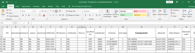
An excel worksheet will be downloaded with a predefined template to enter the details of joints.
- Enter the required joint details in the respective columns of the excel worksheet.
-
Once you have added the joint details in the excel worksheet, save the excel worksheet on your computer.
-
Click
 (IMPORT button). See Fig 3.7.
A new window opens for importing the excel worksheet saved on your computer.

-
Click
 (Browse button) to select the excel worksheet to be uploaded.
 - Select the excel worksheet you want to upload from your computer.
-
Click
 (Upload button) to export the joint details that are added in the excel worksheet.
 The details of the joints in the worksheet will be displayed in the Joints page.


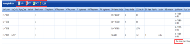
3.8 Drawing Bulk Edit
The Drawing Bulk Edit tab in the Project Data menu helps you to make changes in all the added ISO drawings together, where the ISO drawings are added using the ISO Drawings tab. This feature avoids the need to open each ISO drawing individually for making changes in the ISO drawings because you can make changes in all the ISO drawings together.
If you want to make changes in the ISO drawings together, do the following steps,
- Click Drawing Bulk Edit in the Project Data menu.
The Drawing Bulk Edit page opens with a list ISO drawing added in the ISO Drawings page.
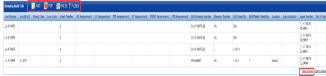
Figure 3.8: Drawing Bulk Edit page
- If you want make changes in any ISO drawing details, click on the respective detail, and edit.
- Click Save Changes.
The changes you have made here will be reflected in the respective ISO drawing in the ISO page.
 Note: You can also add a new ISO drawing by using (ADD Button) provided in the upper side of the Drawing Bulk Edit page.

3.8.1 Export Drawings After Editing
After making changes in the ISO drawings, you can export a list of drawings in the Drawing Bulk Edit page in both the pdf and excel formats by using  (PDF button) and
  (Excel button). To know how to export, see the topic, “Export P&ID list”.
3.8.2 Filter a Drawing
If you want to filter any ISO drawing in the Drawing Bulk Edit page, you can use (FILTER button) provided on the Drawing Bulk Edit page. To know how to filter, see the topic, “Filter P&ID”.
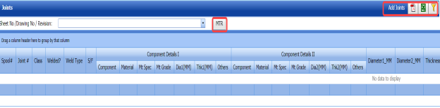
3.9 Joints Bulk Edit
The Joints Bulk Edit tab in the Project Data menu helps you to make changes in all the added joints together, where the joints are added using the Joints tab. This feature avoids the need to open each joint individually for making changes in the joint because you can make changes in all the joints together.
If you want to make changes in the joints together, do the following steps,
- Click Joints Bulk Edit in the Project Data menu.
The Joints page opens with a list joints added in the Joints page.

Figure 3.9: Joints page
-
In the Sheet No/Drawing No/Revision box, select the drawing number from a drop-down list.
The joints corresponding to the selected drawing number will be displayed in the Joints page.

- If you want make changes in any joint, click on the respective joint detail, and edit.
- Click Save Changes.
The changes you have made here will be reflected in the respective joints in the Joints page.
 Note: You can also add a new joint by using provided in the upper right corner of the Joints Bulk Edit page.

3.9.1 Export Joints After Editing
After making changes in the joints, you can export a list of joints in the Joints page in both the pdf and excel formats by using  (PDF button) and
  (Excel button). To know how to export, see the topic, “Export P&ID list”.
3.9.2 Filter a Joint
If you want to filter any joint in the Joints page, you can use  (FILTER button) provided in the Joints page. To know how to filter, see the topic, “Filter P&ID”.
3.9.3 View Material Traceability Record (MTR)
You can view the MTR for added joints by using  (MTR button) provided in the Joints page. Once you click the MTR button, the page redirects you into the Material Traceability Record page.
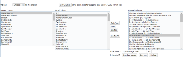
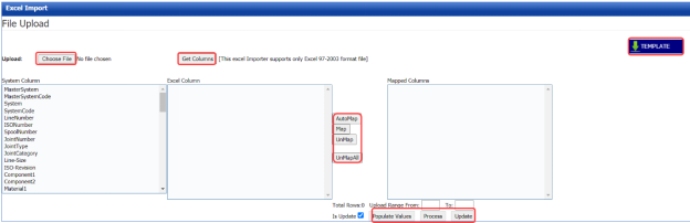
3.10 Import from Excel - Masters
The Import from Excel – Masters tab helps you to upload master data for all fields instead of uploading data for each field individually.
If you want to import master data for different fields, do the following,
- Click Import from Excel – Masters in the Project Data
The File Upload page opens.
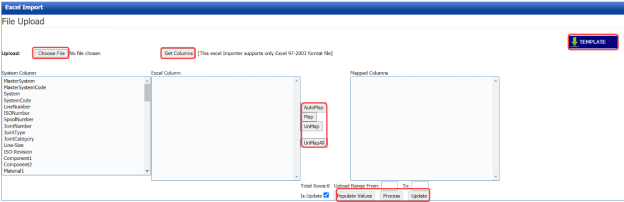
Figure 3.10: File Upload page
-
Download a template by using
 (TEMPLATE button) to enter the details of master data.
An excel worksheet will be downloaded with a pre-defined template to the details.

- Enter the relevant details in the respective column of the excel worksheet.
-
Click
 (Choose File button).
Once the file has been uploaded successfully, you receive a message, “Successfully uploaded”
-
Click
 (Get Columns button).
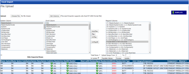
The columns added in the excel worksheet will be listed in the Excel Column field.
 Note: Make sure that the Excel Column field must have all the columns as in the System Column field.
 - To map the columns in the System Column and Excel Column fields, do one of the following,
-
If you want to map the columns Automatically, click
 (AutoMap button).
The columns will be mapped automatically and displayed in the Mapped Columns field.
- If you want to map each column manually, select the respective columns in both the System Columns and Each Excel Column fields and then click
 (Map button).
-
-
To un-map the columns in the Mapped Columns field, select the respective column and then click
 (UnMap button).
Once you have completed the mapping and un-mapping of columns, you must enter the range for uploading the data from the excel worksheet.
 Note: In the Total Rows field, the system indicates the total number of rows filled in the excel worksheet.
 Tip: You must enter the upload starting range as two in the Upload Range From field because a first row in the excel worksheet is having heading of the columns.
 - In the Upload Range From and To fields, enter the range of rows you want to upload from the excel worksheet.
-
Click
 (Populate Values button).
 -
Click
 (Process button).
The system processes all the uploaded data and displays in the Excel Import page.

-
Click
 (Update button) to import the uploaded data.
The data will be successfully imported.


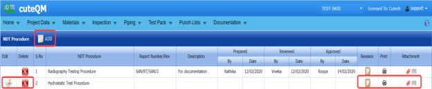
3.11 NDT Procedures
The NDT procedures tab in the Project Data menu helps you to add an NDT procedure. Once you have added the NDT procedure details you can add revision for the added NDT procedure. If you want to add an NDT procedure, do the following steps,
- Click NDT Procedures in the Project Data menu.
The NDT Procedure page opens.

Figure 3.11: NDT Procedure page
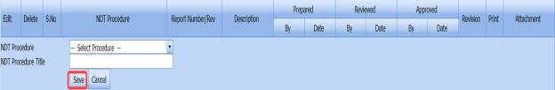
3.11.1 Add an NDT procedure
If you want to add an NDT procedure,
-
Click
 (ADD button) in the NDT Procedure page. See Fig 3.11.
A new window opens to add an NDT procedure.

- In the NDT Procedure box, select the NDT procedure from a drop-down list.
- In the NDT Procedure Title box, enter the NDT procedure title.
- Click Save.
The NDT procedure is successfully added.

3.11.2 Add Details of NDT Procedure
Once you have added the NDT procedure, you must add the details of the added NDT procedure.
-
Click
 (Edit icon) of the respective NDT procedure in the NDT Procedure See Fig 3.11.
The NDT Procedure Revision window opens.

-
Click
 (ADD button) in the NDT Procedure Revision window.
A new window opens to add the NDT procedure details.
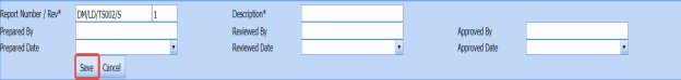
 Note: The fields notified with a symbol (*) are mandatory. You must enter the relevant details in that fields before saving.
 Tip: A report number for the revision will be updated automatically in the Report Number/ Revision box.
 - In the Description box, enter the description for the NDT procedure.
- In the Prepared By box, enter the name a person who has prepared the NDT procedure.
- In the Prepared Date box, enter the prepared date of the NDT procedure.
- In the Reviewed By box, enter the name a person who has reviewed the NDT procedure.
- In the Reviewed Date box, enter the reviewed date of the NDT procedure.
- In the Approved By box, enter the name a person who has approved the NDT procedure.
- In the Approved Date box, enter the approved date of the NDT procedure.
- Click Save.
The NDT procedure details are successfully saved and listed in the NDT Procedure Revision window.

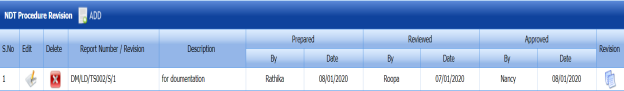


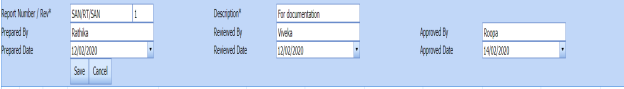
3.11.3 Add Revision for NDT Procedure
Once you have added the NDT procedure details, you can add revision for the added NDT procedures. You can add multiple revisions for one NDT procedure. To add revision,
-
Click
 (Revision icon) of the respective NDT procedure.
A new window opens with the details of existing NDT procedure.

-
Click Save.
The revision for the selected NDT procedure is added.

3.11.4 View an NDT Procedure Report
If you want to view an NDT procedure report, click (print icon) provided in the Print column of the NDT Procedure page. See Fig 3.11.
3.11.5 Attach a File into an NDT Procedure
If you want to attach any file with a NDT procedure listed in the NDT Procedure page, you can attach the file by using  (Attach icon) in the Attachment column. To know how to attach, follow the procedures given in the topic “Attach a file into P&ID”.
3.12 WPS in Project
WPS is a written instruction that specifies materials, consumables and edge preparations for a given joint. The WPS lists the pre- and post-weld operations including heat treatments; machining, grinding, and dressing of the weld.
The WPS in Project tab in the Project Data menu helps you to add a WPS report and assign the WPS to a project.
- Click WPS in Project tab in the Project Data menu.
The WPS by projects page opens with two fields such as WPS Summary and Assign WPS to Project.
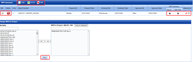
Figure 3.12: WPS in projects page

3.12.1 Add a WPS Summary Report
If you want to add a new WPS summary report, do the following,
-
Click
 (ADD button) in the WPS Summary field. See Fig 3.12.
A new window opens to add a WPS report.

 Tip: A report number for a new WPS report will be updated automatically in the Report Number box. If you want to change the report number, you can change.
 - In the Prepared By box, enter the name of a person who has prepared the WPS report.
- In the Reviewed By box, enter the name of a person who has reviewed the WPS report.
- In the Approved By box, enter the name of a person who has approved the WPS report.
- In the Prepared Date box, choose the prepared date of the WPS report.
- In the Reviewed Date box, choose the reviewed date of the WPS report.
- In the Approved Date box, choose the approved date of the WPS report.
- Click Save.
The WPS summary report is successfully added.


3.12.2 View a WPS Summary Report
If you want to view a WPS summary report, click (Print icon) provided in the WPS Summary Report column.
3.12.3 View a WPS Summary Report with PQR
If you want to view a WPS summary report with PQR, click (Print icon) provided in the WPS Summary with PQR column.
3.12.4 Attach a File into a WPS Summary Report
If you want to attach any file with any WPS summary report listed in the WPS Summary page, you can use  (Attach icon) provided in the Attachment column for the respective WPS summary report. To know how to attach, follow the procedures given in the topic “Attach a file into P&ID”.
3.12.5 Export WPS Summary Reports List
You can export a list of added WPS reports in the pdf and excel formats by using  (PDF button) and
  (Excel button). To know how to export, see the topic, “Export P&ID list”.
3.12.6 Assign a WPS to a Project
The Assign WPS to Project field in the WPS in projects page allows you to assign the WPS to the project. If you want to assign any WPS to the project, do the following,
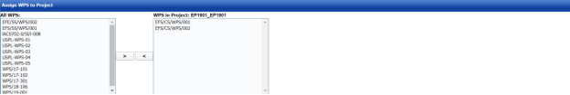
In the Assign WPS to Project field, the All WPS box displays a list of available WPS. The WPS in Project box displays a list of WPS that has been already assigned for the project.
- If you want to assign any WPS for the project, select the respective WPS in the ALL WPS box, and then click
 (Assign welder button).
The selected WPS will be assigned to the project.
- If you want to reject any WPS that has been assigned for the project, select the respective WPS in the WPS in Project box, and then click
 (Reject welder button).


3.13 Welders in Projects
The Welders in Projects tab in the Project Data menu helps you to assign welders for a project. You can add a welder report by using this tab. This tab also helps you to view a welder list and WPQ details.
-
Click Welders in Projects tab in Project Data menu.
The welders in projects page opens with four fields such as Welder Report, Assign Welder to Project, Welder List, and WPQ Details.
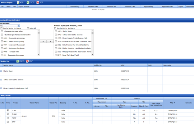
Figure 3.13: Welders in project page

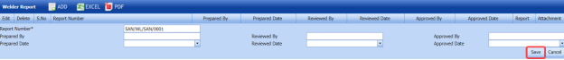
3.13.1 Add a Welder Report
If you want to add a welder report, do the following steps,
-
Click
 (ADD button) in the Welder Report See Fig 3.13.
A new window opens to add a welder report.

 Tip: A report number for a new welder report will be updated automatically in the Report Number box.
 - In the Prepared By box, enter the name of welder who has prepared the welder report.
- In the Received By box, enter the name of welder who has received the welder report.
- In the Approved By box, enter the name of welder who has approved the welder report.
- In the Prepared Date box, choose the prepared date of the welder report.
- In the Received Date box, choose the received date of the welder report.
- In the Approved Date box, choose the approved date of the welder report.
- Click Save.
The welder report is successfully added.


3.13.2 View a Welder Report
If you want to view a welder report, click (Print icon) provided in the Report column.
3.13.3 Attach a File into a Welder Report
If you want to attach any file with any welder report listed in the Welder Report window, you can use (Attach icon) provided in the Attachment column for the respective welder report. To know how to attach, follow the procedures given in the topic “Attach a file into P&ID”.
3.13.4 Export Welder Reports List
You can export a list of welder reports in the Welder Report field in both the pdf and excel formats by using  (PDF button) and
  (Excel button). To know how to export, see the topic, “Export P&ID list”.
3.13.5 Assign a Welder to a Project
The Assign Welder to Project field in the welders in projects page allows you to assign any welder to the particular project. If you want to assign any welder to the project, do the following,
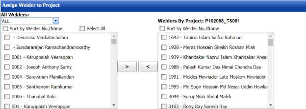
-
In the All Welders box, if you want to view all the welders, click ALL otherwise select the respective company’s welder group from a drop-down list to view their welders list.
Once you have selected the company’s welder group, the left-side box shows a list of welders. The right-side box shows a list of welders who has been already assigned for the project.
-
If you want to assign any welder for the project, select the respective welder in the left-side box, and then click
 (Assign welder button).
The selected welder will be assigned to the project.
-
If you want to reject any welder who has been assigned for the project, select the respective welder in the right-side box, and then click
 (Reject welder button).


3.13.6 Welder List
The Welder List field in the welders in projects page shows the welder details such as welder name, welder number, NRIC, date of birth, and nationality. This field also helps you to assign the WPQs of welders to the project, and remove any WPQs from the project.
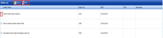
If you click (Expand Icon) of the respective welder, the All WPQ box shows the details of all WPQs of the welder, and the Assigned to Project box shows any WPQ that has been assigned to a project.
-
If you want to assign any WPQ for the project, select the respective WPQ in the All WPQ box, and then click

(Assign WPQ button).
The selected welder will be assigned to the project.
-
If you want to reject any WPQ that has been assigned for the project, select the respective WPQ in the Assigned to Project box, and then click
 (Reject WPQ button).


3.13.7 WPQ Details
The WPQ details field in the welders in projects page shows the WPQ details of each welder including welder’s name, welder number, welding process name, weld metal thickness, position, and so on.
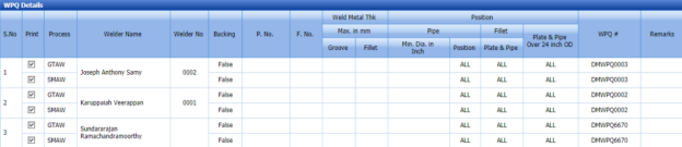
If you want to take a print of any WPQ details, click the checkbox provided in the Print Column.
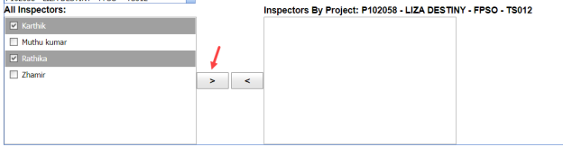
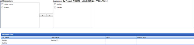
3.14 Inspectors in Projects
The Inspectors in Projects tab in the Project Data menu helps you to map inspectors for the specific project.
-
Click the Inspectors in Projects tab.
The Project Mapping – Inspectors page opens
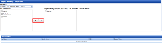
Figure 3.14: Project Mapping – Inspectors page
The Project Mapping – Inspectors page shows a list of inspectors, which is added in the Master Data. If you want to map any inspectors for a specific project, do the following,
- Select a project you want from the Projects box.
A list of available inspectors will be displayed.
-
Select the check box of the respective inspector which you want to map for the selected project.
-
Click
 (Map icon).
The selected inspectors are mapped for the selected project.

The Inspector List window shows the inspector’s name, login name, NRIC, and Date of birth.


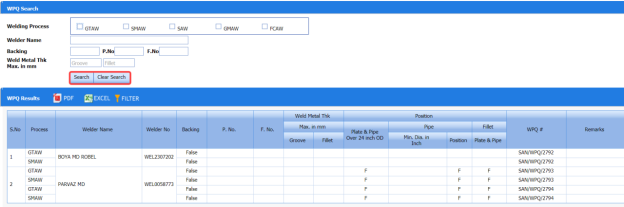
3.15 WPQ Search
The WPQ Search tab in the Project Data menu used to filter the specific WPQ result. To perform the WPQ search,
- Click WPQ Search in the Project Data menu.
The WPQ Search page opens with the WPQ Results window.

Figure 3.15: WPQ Search page
- In the Welding Process box, select a welding process from the given welding processes.
- In the Welder Name box, enter the name of a welder.
- In the Backing box, enter the backing details.
-
In the Weld Metal Thk Max. in mm box, enter the minimum and maximum thickness of the weld metal.
-
Click
 (Search button).
The WPQ Results window shows the WPQ details based on the given data.

3.15.1 Export WPQ Results
You can export the WPQ results in the WPQ Results window in both the pdf and excel formats by using  (PDF button) and
  (Excel button). To know how to export, see the topic, “Export P&ID list”.
3.15.2 Filter WPQ Results
If you want to filter any WPQ in the WPQ Results page, you can use  (FILTER button) provided on the WPQ Results page. To know how to filter, see the topic, “Filter P&ID”.
3.16 Bill of Material
Bill of Material is a comprehensive inventory of the raw materials, assembles, sub assembles, parts and components, as well as the quantity of each, needed to the piping fabrication.
The Bill of Material tab in the Project Data menu used to add a new bill of material.
-
Click Bill of Material in the Project Data menu.
The Bill of Material page opens.
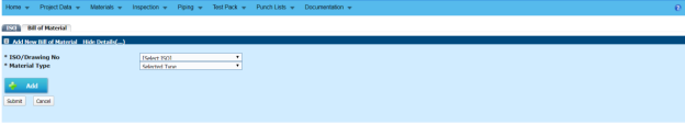
Figure 3.16: Bill of Material page

3.16.1 Add a Bill of Material
If you want to add a bill of material,
- In the ISO/Drawing No box, select the ISO drawing number from a drop-down list.
- In the Material Type box, select a material type from a drop-down list.
-
Click
 (Add button).
A new window opens to add the material details.
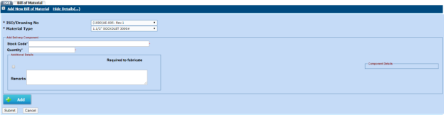
- In the Stock Code box, enter the stock code.
- In the Quantity box, enter the quantity of the material.
- In the Component Details box, enter the component details.
- In the Remarks box, enter your remarks if any.
- If the materials are need to be fabricated, enable the checkbox of the Required to fabricate option.
- Click Submit.
The bill of material is added.


3.17 Spools Location – Masters
The Spools Location – Masters tab in the Project Data menu used to add the details of the spool location.
- Click Spools Location – Masters in the Project Data menu.
The Spools Location page opens.

Figure 3.17: Spools Location page
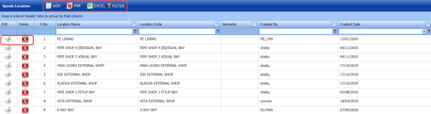
3.17.1 Add a Spool Location
If you want to add a spool location, do the following steps,
-
Click
 (ADD button) in the Spools Location page. See Fig 3.17.
A new window opens to add a new spool location.
- In the Location Name box, enter the location name.
- In the Location Code box, enter the location code.
- In the Remarks box, enter your remarks if any.
- Click Save.
The spool location is successfully added.


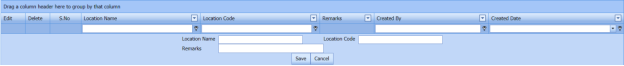
3.17.2 Edit a Spool Location
If you want to edit any existing spool location detail in the Spools Location page,
-
Click
 (Edit icon)of the respective spool location. See Fig 3.17.
The Spools Location page shows the details of the selected location.
- Edit the details where you want.
- Click Save.

3.17.3 Delete a Spool Location
If you want to delete any existing spool location in the Spools Location page, you can use  (Delete icon). To know how to delete, see the topic, “Delete P&ID”.
3.17.4 Export Spool Location List
You can export a list of spool location added in the Spools Location page in both the pdf and excel formats by using  (PDF button) and
  (Excel button). To know how to export, see the topic, “Export P&ID list”.
3.17.5 Filter a Spool Location
If you want to filter any spool location in the Spools Location page, you can use  (FILTER button) provided on the Spools Location page. To know how to filter, see the topic, “Filter P&ID”.
3.18 Workflow Settings
The Workflow Settings tab in the Project Data menu used to set a workflow in the Piping project.
-
Click Workflow Settings in the Project Data menu.
The Workflow page opens.

Figure 3.18: Workflow page
3.18.1 Add a Workflow
If you want to add a workflow,
-
Click
 (ADD button) in the Workflow See Fig 3.18.
The page shows a new window to add the category.
-
In the Category box, select a category from a drop-down list.
- Click Save.
The added category will be listed in the Workflow page. See Fig 3.18.
-
Click
 (Add icon) of the respective category.
The Workflow Details window opens.
-
Click
 (ADD button) in the Workflow Details window.
- In the Role Name box, select a role name from a drop-down list.
- In the Description box, enter the description for the role name.
- Click Save.


3.18.2 Edit a Workflow
If you want to edit any existing workflow in the Workflow page,
-
Click
 (Edit icon) of the respective workflow. See Fig 3.18.
The Workflow page shows the details of the selected workflow.
- Edit the details where you want.
- Click Save.

3.18.3 Delete a Workflow
If you want to delete any existing workflow in the Workflow page, you can use  (Delete icon) provided in the Workflow page. To know how to delete, see the topic, “Delete P&ID”.
3.18.4 Export Workflow List
You can export a list of workflows added in the Workflow page in both the pdf and excel formats by using  (PDF button) and (Excel button). To know how to export, see the topic, “Export P&ID list”.
3.18.5 Filter a Workflow
If you want to filter any specific workflow, you can use  (FILTER button) located on the Workflow page. To know how to filter, see the topic, “Filter P&ID”.
3.19 Inspection Requirements
The Inspection Requirements tab in the Project Data menu used to add the requirement details for the inspection.
- Click Inspection Requirements in the Project Data menu.
The Inspection Requirements page opens.
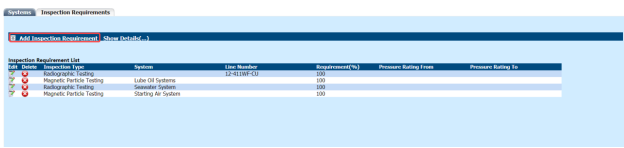
Figure 3.19: Inspection Requirements page

3.19.1 Add an Inspection Requirement
If you want to add an inspection requirement, do the following steps,
-
Click Add Inspection Requirement.
The Add New Inspection Requirement window opens.

-
In the Inspection Type box, select an inspection type.
- If you want to add the system detail, select the System option and choose a system from a drop-down list.
- If you want to add the line number detail, select the Line Number option and choose a line number from a drop-down list.
- In the Requirement box, enter the inspection requirement percentage.
- In the Pressure Rating From and To box, enter the pressure rating range.
- Click Create.
The inspection requirement details will be added and listed in the Inspection Requirements page.
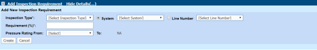
3.19.2 Edit an Inspection Requirement
If you want to edit any added inspection requirement details,
-
Click
 (Edit icon) of the respective inspection requirement. See Fig 3.19.
The added inspection requirement details open.
- Edit the details where you want.
-
Click Save.

3.19.3 Delete an Inspection Requirement
If you want to delete any existing inspection requirement, you can use  (Delete icon). To know how to delete, see the topic, “Delete P&ID”.
3.20 Template Check Sheets
The Template Check Sheets tab in the Project Data menu helps you to add MC/SC – Check Record (CR)/Check Sheet (CS) templates. To navigate to the templates adding page,
- Click Template Check Sheets in the Project Data menu.
The MC/SC – CR/CS Templates page opens.

Figure 3.20: MC/SC – CR/CS Templates page
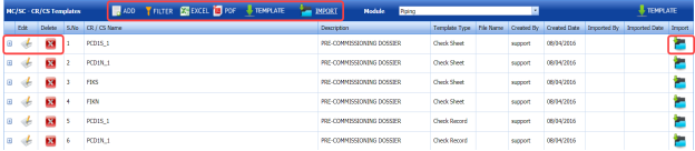
3.20.1 Add a CR/CS Template
If you want to add a CR/CS template,
-
Click
 (ADD button) in the MC/SC – CR/CS Templates page. See Fig 3.20.
The page opens a new window to add the details of a template.
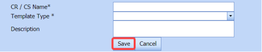
 Note: The field notified with a symbol (*) is mandatory. You must enter the relevant details in that fields before saving.
 - In the CR/CS Name box, enter the name for CR/CS.
- In the Template Type box, select a template whether CR or CS.
- In the Description box, enter the description for CR/CS.
- Click Save.
The template is successfully added and listed in the MC/SC – CR/CS Templates page. Once you have added the template details, you must import the respective template.


3.20.2 Import a CR/CS Template
If you want to import CR/CS template,
-
Click
 (Add icon) of the respective CR/CS name in the MC/SC – CR/CS Templates page.
The Check Records window opens.
-
Click
 (ADD button) in the Check Records
- In Items box, enter the details of items.
- Browse and attach a CS/CR template you want to import.
- Click Save.


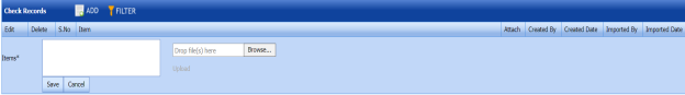
3.20.3 Edit a CR/CS Template
If you want to edit any added CR/CS template in the MC/SC – CR/CS Templates page,
-
Click
 (Edit icon) of the respective CR/CS template. See Fig 3.20
The MC/SC – CR/CS Templates page shows the details of the selected CR/CS template.
-
Edit the details where you want.
-
Click Save.

3.20.4 Delete a CR/CS Template
If you want to delete any existing CR/CS template in the MC/SC – CR/CS Templates page, you can use  (Delete icon) provided in the MC/SC – CR/CS Templates page. To know how to delete, see the topic, “Delete P&ID”.
3.20.5 Export CR/CS Template list
You can export a list of CR/CS templates added in the MC/SC – CR/CS Templates page in both the pdf and excel formats by using  (PDF button) and
  (Excel button). To know how to export, see the topic, “Export P&ID list”.
3.20.6 Filter a CR/CS Template
If you want to filter any specific CR/CS template in the MC/SC – CR/CS Templates page, you can use  (FILTER button) located on the MC/SC – CR/CS Templates page. To know how to filter, see the topic, “Filter P&ID”.
3.20.7 Import Multiple CR/CS Templates
If you want to import multiple CR/CS templates together, do the following,
-
Click
 (TEMPLATE button). See Fig 3.20.
An excel worksheet will be downloaded with a predefined template to enter the details of CR/CS templates.

- Enter the required CR/CS template details in the respective columns of the excel worksheet.
-
Once you have added the CR/CS template details in the excel worksheet, save the excel worksheet on your computer.
-
Click
 (IMPORT button). See Fig 3.20.
A new window opens for importing the excel worksheet saved on your computer.

-
Click
 (Browse button) to select the excel worksheet to be uploaded.
 -
Select the excel worksheet you want to upload from your computer.
-
Click
 (Upload button) to export the CR/CS template details that are included in the excel worksheet.

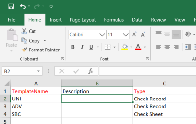


The details of the CR/CS templates in the worksheet will be displayed in the MC/SC – CR/CS Templates page.
3.21 Certificate Template Check Sheets
The Certificate Template Check Sheets tab in the Project Data menu used to add the details included in a certificate.
-
Click Certificate Template Check Sheets in the Project Data.
The Certificates page opens.

Figure 3.21: Certificates page
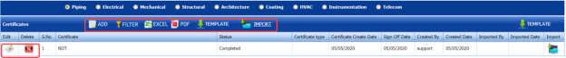
3.21.1 Add a Certificate
If you want to add a certificate,
-
Click
 (ADD button) in the Certificates See Fig 3.21.
The page opens a new window to add the details of a certificate.
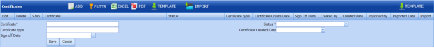
 Note: The field notified with a symbol (*) is mandatory. You must enter the relevant details in that fields before saving.
 - In the Certificate box, enter the name of the certificate.
- In the Status box, select the status of the certificate.
- In the Certificate Type box, enter the description for CR/CS.
- In the Certificate Created Date box, select the created date of the certificate.
- In the Sign off Date box, select the sign off date of the certificate.
- Click Save.


The certificate is successfully added and listed in the Certificates page. Once you have added the certificate details, you must import the respective certificate.
3.21.2 Import a Certificate
If you want to import a copy of the certificate,
-
Click
 (Import icon) of the respective certificate in the Certificates page.
 -
Attach the copy of the certificate.

3.21.3 Edit a Certificate
If you want to edit any added certificate in the Certificates page,
-
Click
 (Edit icon) of the respective certificate. See Fig 3.21.
The Certificates page shows the details of the selected certificate.
- Edit the details where you want.
-
Click Save.

3.21.4 Delete a Certificate
If you want to delete any existing certificate in the Certificates page, you can use  (Delete icon) provided in the Certificates page. To know how to delete, see the topic, “Delete P&ID”.
3.21.5 Export Certificate list
You can export a list of certificates added in the Certificates page in both the pdf and excel formats by using  (PDF button) and
  (Excel button). To know how to export, see the topic, “Export P&ID list”.
3.21.6 Filter a Certificate
If you want to filter any specific certificate in the Certificates page, you can use  (FILTER button) located on the Certificates page. To know how to filter, see the topic, “Filter P&ID”.
3.21.7 Import Multiple Certificates
If you want to import multiple certificates together, do the following,
-
Click
 (TEMPLATE button). See Fig 3.21.
An excel worksheet will be downloaded with a predefined template to enter the details of certificates.
- Enter the required certificate details in the respective columns of the excel worksheet.
-
Once you have added the certificate details in the excel worksheet, save the excel worksheet on your computer.
-
Click
 (IMPORT button). See Fig 3.21.
A new window opens for importing the excel worksheet saved on your computer.

-
Click
 (Browse button) to select the excel worksheet to be uploaded.
 - Select the excel worksheet you want to upload from your computer.
-
Click
 (Upload button) to export the certificate details that are included in the excel worksheet.


The details of the certificates in the worksheet will be displayed in the Certificates page.
3.22 Welder Qualification Test Coupon
The Welder Qualification Test Coupon tab in the Project Data menu used to add the welder qualification test coupon details.
If you want to add a welder qualification test coupon, do the following steps,
-
Click Welder Qualification Test Coupon in the Project Data menu.
The Welder Qualification Test Coupon page opens.

Figure 3.22: Welder Qualification Test Coupon page

3.22.1 Add a Welder Qualification Test Coupon
If you want to add a welder qualification test coupon report,
-
Click
 (ADD button) in the Welder Qualification Test Coupon page. See Fig 3.22.
A new window opens to add the welder qualification test coupon.

 Tip: A report number for a new welder qualification test coupon will be updated automatically in the Report Number box.
 - In the Test Date box, select the welder qualification test date.
- In the Work Order box, enter the work order name.
-
Click Save.


The welder qualification test coupon will be added and listed in the Welder Qualification Test Coupon.
3.22.2 Add Welder Qualification Test Coupon Details
To add the welder qualification test coupon details,
-
Click
 (Add icon) of the respective test coupon. See Fig 3.22.
The WQTC Details window opens.

-
Click
 (ADD button) in the WQTC Details window.
A new window opens to enter the WQTC details.
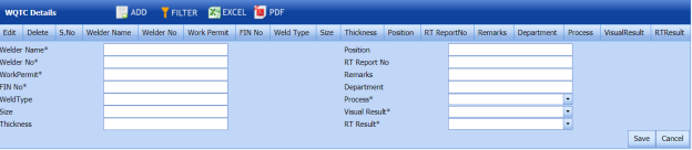
-
In the Welder Name box, enter the welder name.
-
In the Position box, enter the position detail.
- In the Welder No box, enter the welder number.
- In the RT Report No box, enter the RT report number.
- In the Work Permit box, enter the work permit detail.
- In the Remarks box, enter your remarks if any.
- In the FIN No box, enter the FIN number.
- In the Department box, enter the department name.
- In the Weld Type box, enter the welding type.
- In the Process box, select the welding process.
- In the Size box, enter the welding size.
- In the Visual Result box, select the visual result.
- In the Thickness box, enter the thickness of the welding.
-
In the RT Result box, select the RT result.
- Click Save.


3.22.3 View a Welder Qualification Test Coupon Report
To view a welder qualification test coupon report, click (Print icon) of the respective test coupon, which is provided in the Report column of the Welder Qualification Test Coupon page.
3.22.4 Approve a Welder Qualification Test Coupon
Once you have added the welder qualification test coupon details, you must approve the test coupon. To approve the test coupon,
-
Click
 (Submit icon) in the Action column.

3.33.5 Export Welder Qualification Test Coupon List
You can export a list of test coupons added in the Welder Qualification Test Coupon page in both the pdf and excel formats by using  (PDF button) and
  (Excel button). To know how to export, see the topic, “Export P&ID list”.
3.33.6 Filter a Welder Qualification Test Coupon
If you want to filter any specific test coupon in the Welder Qualification Test Coupon page, you can use  (FILTER button) located on the page. To know how to filter, see the topic, “Filter P&ID”.
3.23 Valve List
The Valve List tab in the Project Data menu helps you add the valve details.
-
Click Valve List in the Project Data menu.
The Valve List page opens.
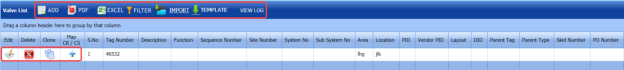
Figure 3.23: Valve List page

3.23.1 Add a Valve
If you want to add a new valve, do the following steps,
-
Click
 (ADD button) in the Valve List page. See Fig 3.23.
A new window opens to add a new valve.
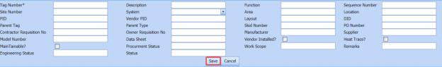
 Note: The fields notified with a symbol (*) are mandatory. You must enter the relevant details in that fields before saving.
 - In the Tag Number box, select the tag number of the valve.
- In the Description box, enter the description for the valve.
- In the Function box, enter the function name.
- In the Sequence Number box, enter the sequence number of the valve.
- In the Site Number box, enter the site number.
- In the System box, select a system.
- In the Area box, enter the area name.
- In the Location box, enter the location name.
- In the PID box, enter the PID number.
- In the Vendor PID box, enter the vendor PID number.
- In the Layout box, enter the layout detail.
- In the Parent tag box, enter the parent tag number.
- In the Parent type box, enter the parent type.
- In the Skid Number box, enter the skid number.
- In the PO Number box, enter the PO number.
- In the Manufacturer box, enter the manufacturer name.
- In the Supplier box, enter the supplier name.
- In the Model Number box, enter the model number of the valve.
- In the Data Sheet box, enter the data sheet detail.
- In the Procurement Status box, enter the procurement status detail.
- In the Remarks box, enter your remarks if any.
- Click Save.
The valve is successfully added.


3.23.2 Clone a Valve
The Clone option provided in the Valve List page used to add a new valve from previously added valve. If a valve to be added is having the same specifications of any valve already listed in the Valve List page, you can add the new valve by using  (Clone icon).
-
In the Valve List page, find out the valve you want to clone.
-
Click
 (Clone icon) of the respective valve.
 The Valve List page shows the details of selected valve. See the below figure.

- If you want to change any details, you can change in the respective boxes.
- Click Save.
The new valve is successfully added and listed in the Valve List page.

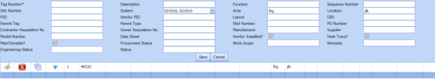
3.23.3 Edit a Valve
If you want to edit any existing valve in the Valve List page,
-
Click
 (Edit icon) of the respective valve. See Fig 3.23.
The Valve List page shows the details of the selected valve.
- Edit the details where you want.
- Click Save.

3.23.4 Delete a Valve
If you want to delete any existing valve in the Valve List page, you can use  (Delete icon) provided in the Valve List page. To know how to delete, see the topic, “Delete P&ID”.
3.23.5 Export Valve List
You can export a list of valves added in the Valve List page in both the pdf and excel formats by using  (PDF button) and
  (Excel button). To know how to export, see the topic, “Export P&ID list”.
3.23.6 Filter a Valve
If you want to filter any valve in the Valve List page, you can use  (FILTER button) provided on the Valve List page. To know how to filter, see the topic, “Filter P&ID”.
3.23.7 Import Multiple Valves
If you want to import multiple valves together, do the following,
-
Click
 (TEMPLATE button). See Fig 3.23.
An excel worksheet will be downloaded with a predefined template to enter the details of joints.
- Enter the required valve details in the respective columns of the excel worksheet.
-
Once you have added the valve details in the excel worksheet, save the excel worksheet on your computer.
-
Click
 (IMPORT button). See Fig 3.23.
A new window opens for importing the excel worksheet saved on your computer.

-
Click
 (Browse button) to select the excel worksheet to be uploaded.
 -
Select the excel worksheet you want to upload from your computer.
-
Click
 (Upload button)to export the valve details that are added in the excel worksheet.


The details of the valves in the worksheet will be displayed in the Valve List page.
3.24 Special Component
The Special Component tab in the Project Data menu used to add any special component to be used in the Piping project.
To add the details of special component, follow the same procedure given in the topic, “Valve List”.
Materials
4.0 Materials
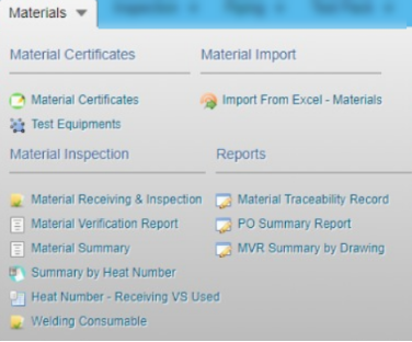
- The Material Certificates option helps you to add certificates details of the materials to be in the piping project.
- The Material Import option helps you to add the bulk materials.
- The Material Inspection option helps you to add material receiving and inspection report, and material summary by heat number.
-
The Reports option used to add material traceability record.
4.1 Material Certificates
Material certificate (Mill certificate) is a certificate document used to certify that the product is produced by manufacturing standards of the mill. The material certificate contains the following information: component name, manufacturer name, certification ID, component dimension and heat numbers. Once you have received the materials from the manufacturer, you must enter the details of material certificates.
The Mill Certificates tab used to add the received material certificate details. If you want to add material certificate details, do the following,
- Click Material Certificates in the Materials menu.
The Mill Certificates page opens.
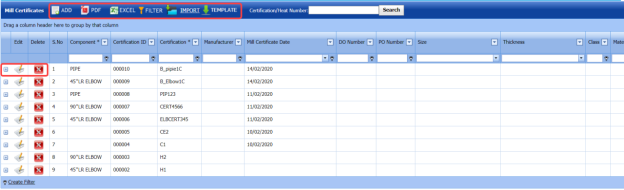
Figure 4.1: Mill Certificates page

4.1.1 Add a Material Certificate
If you want to add a material certificate, do the following,
-
Click
 (ADD button) in the Mill Certificates See Fig 4.1.
A new window opens to add a material certificate.

 Note: The field notified with a symbol (*) is mandatory. You must enter the relevant details in that fields before saving.
 - In the Component box, select the received component from a drop-down list.
- In the Certification box, enter the certification number of the component.
- In the Manufacturer box, enter the name of the manufacturer.
- In the Mill Certificate Date box, choose the mill certificate date.
- In the Delivery Order (DO) Number box, enter the delivery order number of the component.
-
In the Purchase Order (PO) Number box, enter the purchase order number of the component.
- In the Size box, select the size of the received component.
- In the Thickness box, select the thickness of the received component.
- In the Class box, enter the class of the received component.
- In the Material box, select the type of material where the component is made from.
- In the Rating box, enter the rating of the component.
- In the Expiry Date box, choose the expiry date of the component.
-
Click Save.

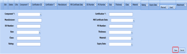

The material certificate is successfully added. Once you have added the mill certificate, you must add heat numbers for the added component.
4.1.2 Add Heat Numbers of Material
If you want to add heat numbers, do the following steps,
-
Click
 (Add icon) of the respective mill certificate.
The Heat Numbers box opens.

Figure 4.1.1: Heat Numbers page
-
Click
 (ADD button) in the Heat Numbers box.
A new window opens to add the heat number.

-
In the planned Project box, select a project you want from a drop-down list.
- In the Heat Number box, enter the heat number.
- In the Remarks box, enter your remarks if any.
- Click Save.
The heat number is successfully added for the specific component.
 Note: You can edit and delete the added heat numbers by using the respective
  (Edit icon) and
  (Delete icon).

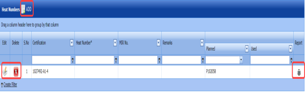


4.1.3 Edit a Mill Certificate
If you want to edit any existing mill certificate in the Mill Certificates page, do the following,
-
Click
 (Edit icon) in the Edit column for the respective mill certificate. See Fig 4.1.
A new window opens including the added mill certificate details.
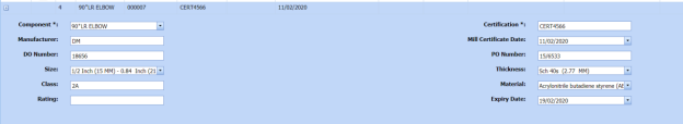
- Click any box where you want to edit the details, and then edit the details in the respective box.
-
Click Save.


4.1.4 Delete a Mill Certificate
If you want to delete any existing mill certificate in the Mill Certificates page, you can use (Delete icon) provided in the Mill Certificates page. To know how to delete, see the topic, “Delete P&ID”.
4.1.5 Export Mill Certificates List
You can export a list of mill certificates added in the Mill Certificates page in both the pdf and excel formats by using  (PDF button) and
  (Excel button). To know how to export, see the topic, “Export P&ID list”.
4.1.6 Filter a Mill Certificate
If you want to filter any specific mill certificate in the Mill Certificates page,
-
you can use the filter box
provided in the upper side of the Mill Certificates To filter the mill certificate, enter the certification or heat number in the box and click Search.
-
you can also use
 (FILTER button) located on the Mill Certificates To know how to filter using the Filter button, see the topic, “Filter P&ID”.


4.1.7 Import Multiple Mill Certificates
If you want to import multiple mill certificates together, do the following,
-
Click
 (TEMPLATE button) on the Mill Certificates See Fig 4.1
A template will be downloaded as an excel worksheet with a pre-defined template to enter the details of multiple mill certificates.
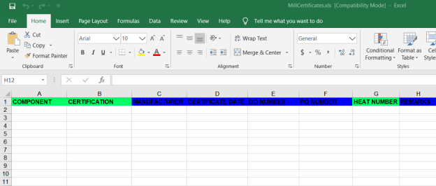
-
Enter the relevant details in the required columns on the excel worksheet.
-
Once you have added the mill certificates details in the excel worksheet, save the excel worksheet on your computer.
-
Click
 (IMPORT button). See Fig 4.1.
A new window opens for importing the excel worksheet saved on your computer.

-
Click
 (Browse button) to select the excel worksheet to be uploaded.
 - Select the excel worksheet you want to upload from your computer.
-
Click
 (Upload button) to export the mill certificates that are included in the excel worksheet.
The details of the mill certificates in the worksheet will be displayed in the Mill Certificates page.


4.1.8 Attach a File into a Mill Certificate
If you want to attach any file with a mill certificate listed in the Mill Certificates page, you can attach the file by using  (Attach icon) in the Attachment column. To know how to attach, follow the procedures given in the topic “Attach a file into P&ID”.
4.2 Test Equipments
The Test Equipments tab in the Materials menu used to add the details of a test equipment to be used in the piping project. To add a test equipment,
- Click Test Equipments in the Materials menu.
The Testing Equipments page opens.
Figure 4.2: Testing Equipments page
4.2.1 Add a Test Equipment
If you want to add a test equipment, do the following steps,
-
Click
 (ADD button) in the Testing Equipments See Fig 4.2.
A new window opens to add a test equipment.
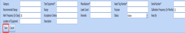
 Note: The field notified with a symbol (*) is mandatory. You must enter the relevant details in that fields before saving.
 -
In the Category box, enter the category of the test equipment.
- In the Test Equipment box, enter the name of the test equipment.
- In the Manufacturer box, enter the name of the manufacturer.
- In the Asset Tag Number box, enter the asset tag number of the test equipment.
- In the Serial Number box, enter the serial number of the test equipment.
- In the Recommended Range box, enter the recommended range of test equipment.
- In the Range box, enter the actual range of test equipment.
- In the Least Count box, enter the least count of the test equipment.
- In the Purpose box, enter the purpose of the test equipment.
-
In the Calibration Frequency (in Months) box, the calibration frequency duration will be updated automatically. If you want to change the duration you can change.
- In the Alert Frequency(in Days) box, the alert frequency duration will be updated automatically. If you want to change the duration you can change.
- In the Acceptance Criteria box, enter the acceptance criteria.
- In the Remarks box, enter your remarks if any.
- In the Status box, select the status of the test equipment.
- In the Location of Equipment box, enter the equipment location detail.
- In the Description box, enter the description for the test equipment.
- Click Save.
The test equipment is successfully saved.


4.2.2 Update Calibration Details
Once you have added the test equipment, you must add the details of calibration, where the calibration is comparison between a standard measurement and the measurement using the test equipment. To add the calibration details,
-
Click
 (Add icon) of the respective test equipment.
The Calibration window opens.

-
Click
 (ADD button) in the Calibration window.
A new window opens to add the calibration details.

-
In the Calibration Report Number box, enter the calibration report number.
-
In the Calibration Date box, select the calibration date.
- In the Calibration By box, enter the name of a person who has calculated the calibration.
- In the Calibration Due Date box, select the due date of calibration.
-
In the Preparation By box, enter the name of a person who has prepared the calibration report.
- In the Approved By box, enter the name of a person who has approved the calibration report.
- Click Update.
The calibration details will be updated.
-
If you want to add additional data, click Additional Data option in the Calibration window.
The Additional Parameter window opens.

-
-
Click
 (ADD button) in the Additional Parameter
 - In the Nominal Value column, enter the nominal value.
- In the Measured Value column, enter the measured value.
- Click Save Changes.
-
-
-
If you want to add pressure data, click Pressure Data option in the Calibration window.
The Pressure Recorder Data window opens.
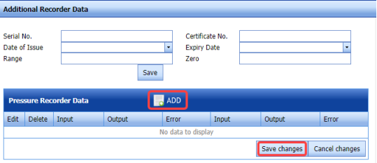
-
- In the Additional Recorder Data field, enter the details of additional recorder data.
-
Click
 (ADD button) in the Pressure Recorder Data window.
 - In the Input and Output columns, enter the input and output values.
- In the Error column, enter the error value.
-
Click Save Changes.
-
- If you want to add temperature data, click Temperature Data option in the Calibration window.
The Temperature Recorder Data window opens.
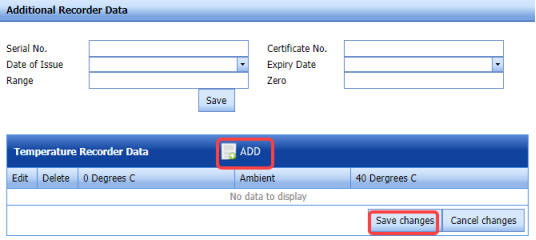
-
- In the Additional Recorder Data field, enter the details of additional recorder data.
-
Click
 (ADD button) in the Temperature Recorder Data window.
 - In the 0 Degrees C column, enter the calibration value at 0 degree.
- In the Ambient column, enter the ambience value.
- In the 40 Degrees C column, enter the calibration value at 40 degree.
- Click Save Changes.
-


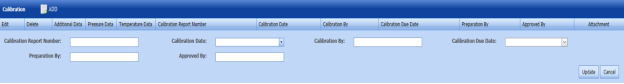
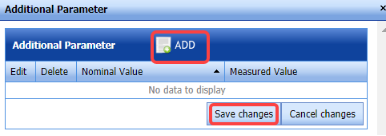


4.2.3 Edit a Test Equipment
If you want to edit any existing test equipment in the Testing Equipments page,
-
Click
 (Edit icon) of the respective test equipment. See Fig 4.2.
The Testing Equipment page shows the details of the selected test equipment.
-
Edit the details where you want.
-
Click Save.

4.2.4 Delete a Test Equipment
If you want to delete any existing test equipment in the Testing Equipment page, you can use  (Delete icon) provided in the Testing Equipment page. To know how to delete, see the topic, “Delete P&ID”.
4.2.5 Export Test Equipment list
You can export a list of test equipments added in the Test Equipment page in both the pdf and excel formats by using  (PDF button) and
  (Excel button). To know how to export, see the topic, “Export P&ID list”.
4.2.6 Filter a Test Equipment
If you want to filter any specific test equipment in the Testing Equipment page,
-
you can use the category wise filter box
 provided in the upper side of the Testing Equipment To filter the testing equipment, select the category from the drop-down list.
 -
you can also use
 (FILTER button) located on the Testing Equipment To know how to filter using the Filter button, see the topic, “Filter P&ID”.


4.2.7 Import Multiple Test Equipments
If you want to import multiple test equipments together, do the following,
-
Click
 (TEMPLATE button). See Fig 4.2.
An excel worksheet will be downloaded with a predefined template to enter the details of test equipments.
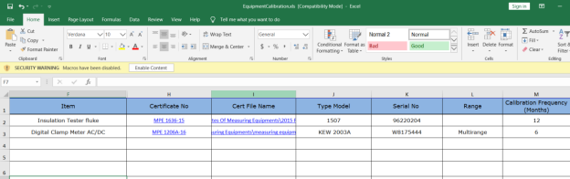
- Enter the required test equipment details in the respective columns of the excel worksheet.
-
Once you have added the test equipment details in the excel worksheet, save the excel worksheet on your computer.
-
Click
 (IMPORT button). See Fig 4.2.
A new window opens for importing the excel worksheet saved on your computer.

-
Click
 (Browse button) to select the excel worksheet to be uploaded.
 - Select the excel worksheet you want to upload from your computer.
-
Click
 (Upload button) to export the test equipment details that are included in the excel worksheet.
The details of the test equipments in the worksheet will be displayed in the Testing Equipment page.


4.2.8 Attach a File into a Test Equipment
If you want to attach any file with any existing test equipment listed in the Testing Equipment page, you can attach the file by using  (Attach icon) in the Attachment column. To know how to attach, follow the procedures given in the topic “Attach a file into P&ID”.
4.2.9 View a Calibration History Card
To view a calibration history card, click (Print icon) of the respective test equipment, which is provided in the Report column of the Testing Equipment page.
4.3 Material Receiving and Inspection (Heat Numbers)
Material Receiving Inspection validates quality of purchased raw materials based on set acceptance criteria before the materials are used for the piping project.
The Material Receiving and Inspection tab in the Materials menu helps you to add an incoming material inspection report (MIR). Incoming MIR includes material name, material size, material specification, heat numbers, and material type.
If you want to add an incoming MIR, do the following,
- Click the Material Receiving and Inspection tab in the Materials
The Incoming Material Inspection Report page opens.
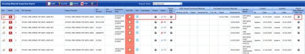
Figure 4.3: Incoming Material Inspection Report page

4.3.1 Add an Incoming MIR
If you want to add an incoming MIR,
-
Click
 (ADD button) in the Incoming Material Inspection Report page. See Fig 4.3.
A new window opens to add an incoming MIR.

 Note: The fields notified with a symbol (*) are mandatory. You must enter the relevant details in that fields before saving.
 Tip: A report number and a Request for Inspection (RFI) number for a new MIR will be updated automatically in the Report Number and the RFI Number boxes, respectively.
 - In the Delivery Order Number box, enter the material’s delivery order number.
- If the materials are received from a client, select the SAN Incoming Materials option, and then enter the relevant details in the respective boxes.
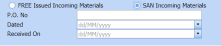
-
- In the P.O. No box, enter the purchase order number.
- In the Dated box, choose the date of the purchase order.
- In the Received On box, select the received date of materials.
-
- If the materials are purchased from outside, select the FREE Issued Incoming Materials option, and then enter the relevant details in the respective boxes.

-
-
In the Packing List No box, enter the packing list number.
- In the Dated box, choose the date of packing.
- In the Received On box, choose the received date of materials.
-
-
- In the Inspection Date box, choose the date of inspection.
- In the Vendor Name box, enter the vendor name.
- In the Request Description box, enter the request description.
- In the ITP Number box, select an ITP number.
- In the Delivery Note box, enter the delivery note.
- In the Location box, enter the location name.
- In the Sub Contractor box, select the subcontractor name from a drop-down list.
- Click Save.
The incoming MIR is successfully added. Once you have added the MIR, you must add the material details for the added MIR.

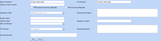


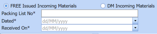
4.3.2 Add Materials for an Incoming MIR
If you want to add the details of materials for the added incoming MIR, do the following steps,
-
Click
 (Edit icon) in the Edit MIR column of the Incoming Material Inspection Report See Fig 4.3.
The Add/Edit - Materials window opens.
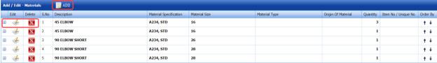
Figure 4.3.1: Add/Edit – Materials window
-
Click
 (ADD button) in the Add/Edit - Materials window,
A new window opens to add the material details.

 Note: The fields notified with a symbol (*) are mandatory. You must enter the relevant details in that fields before saving.
 - In the Material Description box, enter the material description.
- In the Material Size box, select the size of the material.
- In the Material Specification box, enter the material specification.
- In the Material Type box, enter the type of the material.
- In the Quantity Required box, enter the required quantity of the material.
- In the Item No box, enter the item number.
- In the Weight box, enter the weight of the material.
- In the Component box, select a component.
-
Click Update.
Once you have added the material details, you must add the heat numbers for the added materials.


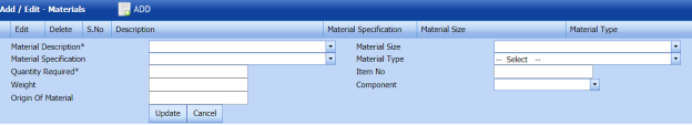

4.3.3 Add Heat Numbers
-
Click
 (Add icon) of the respective material in the Add/Edit - Materials window. See Fig 4.3.1.
The Heat Numbers window opens.

-
Click
 (ADD button) in the Heat Numbers window.
A new window opens to add a heat number.

-
In the Heat Number/Certificates box, select the heat number from a drop-down list.
-
In the Plate Number/Coil Number/ Tag Number box, enter the plate number or coil number or tag number of the material.
- In the Delivery Quantity (Total) box, enter the total delivery quantity of the material including UOM.
- In the Delivery Quantity (Partial) box, enter the partial delivery quantity of the material including UOM.
- In the Dimensions option, select Accepted or Rejected based on the inspection detail.
- In the Visual option, select Accepted or Rejected based on the inspection detail.
- In the Mill Test Certificates (MTC) option, select Accepted or Rejected based on the inspection detail.
- In the Remarks box, enter your remarks if any.
- If the heat treatment is required for the material, select YES in the Heat Treatment Otherwise select NO.
- In the NDE is required for the material, select YES in the NDE Otherwise select NO.
-
Click Update.
 Note: If you want to manage the review material TC, click
  (Add icon). The Review Material TC window opens to add the material checklist detail.

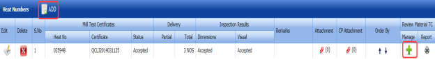

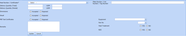


4.3.4 Add MIR Details
If you want to add the details of MIR,
-
Click
 (Add icon) in the Add See Fig 4.3.
The MIR Details window opens.

- In the Manufacturer Name box, enter the manufacturer name.
- In the Supplier box, enter the supplier name.
- In the Unloaded box, enter the unloaded detail.
- In the Date box, select the date of MIR.
- In the Truck/Trailer No box, enter the truck/trailer number.
- In the Defect Report No box, enter the defect report number.
- In the Storage Area box, enter the storage area name.
- In the Defect box, enter the defect detail.
- In the Remarks box, enter your remarks if any.
-
Click Save.

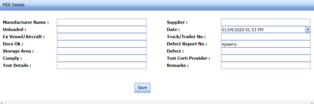
4.3.5 Print an Incoming MIR Report
If you want to print an incoming MIR report, click (print icon) provided in the Report column of the Incoming Material Inspection Report page. See Fig 4.3.
4.3.6 Print a Report with MTC
If you want to print an incoming MIR report including MTC, click  (print icon) provided in the Report with MTC column of the Incoming Material Inspection Report page. See Fig 4.3.
4.3.7 Print a Report Raw Material Offer List
If you want to print a report raw material offer list, click  (print icon) provided in the Report Raw Material Offer List column of the Incoming Material Inspection Report page. See Fig 4.3.
4.3.8 Print a MIR Summary Report
If you want to print a MIR summary report, click  (print icon) provided in the upper side of the Incoming Material Inspection Report page. See Fig 4.3.
4.3.9 Attach a File into an Added Incoming MIR
If you want to attach any file with any incoming MIR listed in the Incoming Material Inspection Report page. To know how to attach, follow the procedures given in the topic “Attach a file into P&ID”.
4.3.10 Edit an Incoming MIR
If you want to edit any existing incoming MIR in the Incoming Material Inspection Report page, do the following,
-
Click
 (Edit icon)in the Edit column for the respective MIR. See Fig 4.3.
A new window opens to edit the added incoming MIR.
-
Click any box where you want to edit the details, and then edit the details in the respective box.
- Click Save.

4.3.11 Delete an Incoming MIR
If you want to delete any specific incoming MIR from the list of MIRs, you can use  (Delete icon) provided in the Delete column of the Incoming Material Inspection Report page. To know how to delete, see the topic, “Delete P&ID”.
4.3.12 Filter an incoming MIR
If you want to filter any incoming MIR from the list of MIRs in the Incoming Material Inspection Report page,
-
you can use the request status wise filter box

provided in the upper side of the Incoming Material Inspection Report page.
-
you can also use
 (FILTER button) located on the Incoming Material Inspection Report To know how to filter using the Filter button, see the topic, “Filter P&ID”.


4.3.13 Export incoming MIR list
You can export a list of MIR added in the Incoming Material Inspection Report page in the pdf and excel formats by using  (PDF button) and
  (Excel button). To know how to export, see the topic, “Export P&ID list”.
4.4 MVR Inspection Request (Heat Numbers)
MVR will be used while go for material inspection. The Material Verification Report tab in the Materials menu helps you to add an MVR inspection request. If you want to add an MVR inspection request, do the following steps,
-
Click Material Verification Report in the Materials menu.
The MVR Inspection Request page opens.

Figure 4.4: MVR Inspection Request page
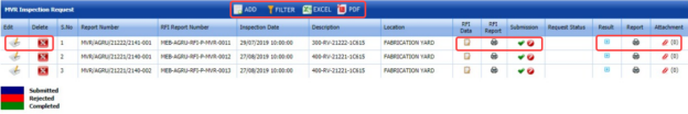
4.4.1 Add an MVR Inspection Request
If you want to add an MVR inspection request,
-
Click
 (ADD button) in the MVR Inspection Request page. See Fig 4.4.
A new window opens to add an MVR inspection request.

 Note: The fields notified with a symbol (*) are mandatory. You must enter the relevant details in that fields before saving.
 Tip: A report number and an RFI report number for a new MVR will be updated automatically in the Report Number and the RFI Report Number boxes, respectively.
 - In the Inspection Date box, choose the date of inspection.
- In the Description box, enter the description for the MVR.
- In the Location box, select a location from a drop-down list.
- Click Save.
The MVR is successfully added. Once you have added the MVR, you must add the RFI data for the added MVR.

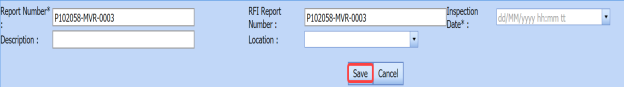


4.4.2 Add RFI Data for an Added MVR Inspection Request
If you want to add the details of RFI data for the added MVR inspection request, do the following,
-
Click
 (Edit icon) in the RFI Data column of the MVR Inspection Request See Fig 4.4.
The RFI Inspection Request List window opens.

-
In the Inspection From box, enter the detail from where the inspection should start.
- In the Inspection To box, enter the detail to where the inspection should end.
- In the Inspection Details option, select 1stInspection, 2nd Inspection or 3rd Inspection according to the inspection details.
- In the Others box, enter any other inspection related details.
- In the Refer to Report No box, enter the report number for reference.
- In the RFI Date box, choose the RFI date.
- In the Inspection Result option, if the inspection result is accepted, select Accepted otherwise select Rejected.
- In the Remarks box, enter your remarks if any.
- In the Inspected by box, enter the name of a person who has done inspection.
- In the Inspected Date box, choose the date of inspection.
- In the Witnessed By box, enter the name of the witnessed person.
- In the Witnessed Date box, choose the date of witnessed.
- In the PCML Rep Name box, enter the representative name of PCML.
- In the PCML Rep Date box, choose the PCML rep date.
- In the MEB Rep Name box, enter the representative name of MEB.
- In the MEB Rep Date box, choose MEB rep date.
-
Click Save.
Once you have added the RFI data, you must add the result for the added MVR inspection request.


4.4.3 View an RFI Report
If you want to print an RFI report, click (print icon) provided in the RFI Report column of the MVR Inspection Request page. See Fig 4.4.
4.4.4 Add Result for an Added MVR Inspection Request
-
Click
 (Add icon) of the respective report number.
The MVR Inspection Request Details window opens.

-
Click
 (ADD button) in the MVR Inspection Request Details window.
A new window opens to add result.
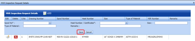
-
In the Spool No box, select the spool number from a drop-down list.
- In the Heat Number / Certificates box, select the heat number from a drop-down list.
- In the Size box, enter the size of the material.
- In the Type of Material box, enter the type of material.
- In the Remarks box, enter your remarks if any.
- Click Save.
Once you have added the result for the MVR inspection request, you must submit and approve the MVR inspection request.

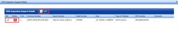


4.4.5 Submit and Approve an MVR Inspection Report
Once you have added the result, the Submission column in the MVR Inspection Request page is appeared with  (Submit and Reject icons).
-
If you want to submit the MVR inspection request, click
 (Submit icon) in the Submission column. Otherwise click
  (Reject icon) to reject the request.
Once you have submitted the MVR inspection request, the Request Status column in the MVR Inspection Request page is appeared with
 (Accept and Reject icons).
 -
If you want to approve the MVR inspection request, click (Submit icon) in the Request Status column. Otherwise click
 (Reject icon) to reject the request.


4.4.6 Print an MVR Inspection Report
If you want to print an MVR inspection report, click  (print icon) in the Report column of the MVR Inspection Request page. See Fig 4.4.
4.4.7 Attach a File into an MVR Inspection Request
If you want to attach any file with an existing MVR inspection request listed in the MVR Inspection Request page, you can attach the file by using  (Attach icon) in the Attachment column. To know how to attach, follow the procedures given in the topic “Attach a file into P&ID”.
4.4.8 Edit an MVR inspection request
If you want to edit any existing MVR inspection request in the MVR Inspection Request page, do the following,
-
Click
 (Edit icon)in the Edit column for the respective MVR inspection request. See Fig 4.4.
A new window opens to edit the MVR inspection request.
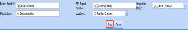
-
Click any box where you want to edit the details, and then edit the details in the respective box.
- Click Save.


4.4.9 Filter an MVR inspection request
If you want to filter any MVR request from the list of requests in the MVR Inspection Request page, you can use  (FILTER button). To know how to filter, see the topic, “Filter P&ID”.
4.4.10 Export MVR inspection request list
You can export a list of MVR inspection requests added in the MVR Inspection Request page in the pdf and excel formats by using  (PDF button) and
  (Excel button). To know how to export, see the topic, “Export P&ID list”.
4.5 Material Summary
The Material Summary tab in the Materials menu used to track the material summary details. If you want to track the summary details of the material, do the following steps,
-
Click the Material Summary tab in the Materials menu.
The Material Summary Details page opens.

Figure 4.5: Material Summary Details page
-
In the Material Specification box, enter the material specification.
-
In the From and To boxes, choose the from and to dates to get the material summary details.
-
Click Search.
The summary details of the added material specification will be displayed for the selected period.
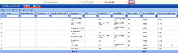
4.5.1 Export Material Summary Details
You can export the material summary details in the Material Summary Details page in both the pdf and excel formats by using  (PDF button) and
  (Excel button). To know how to export, see the topic, “Export P&ID list”.
4.6 Material Summary by Heat Number
The Summary by Heat Number tab in the Materials menu used to track the material summary details by using the respective heat numbers. If you want to track the summary details of the material, do the following steps,
-
Click the Summary by Heat Number tab in the Materials menu.
The Material Summary Details (By Heat Number) page opens.

Fig 4.6: Material Summary Details (By Heat Number) page
- In the Heat Number box, select the heat number from a drop-down list.
-
Click Search.
The material summary details corresponding to the selected heat number will be displayed.
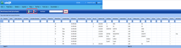
4.6.1 Export Material Summary Details (by Heat Number)
You can export the material summary details in the Material Summary Details (By Heat Number) page in both the pdf and excel formats by using  (PDF button) and
  (Excel button). To know how to export, see the topic, “Export P&ID list”.
4.7 Heat Number – Receiving vs Used
You can view the history of received and used heat numbers of materials by using this Heat Number – Receiving vs Used tab in the Materials menu.
- Click Heat Number – Receiving vs Used in the Materials menu.
The Material Heat Number – Receiving vs Used page opens.

Figure 4.7: Material Heat Number – Receiving vs Used page
This page shows the details of component names, heat numbers, and number of quantities received and used.
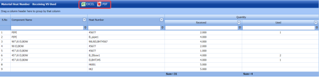
4.7.1 Export Material Heat Number Received vs Used History
You can export the material heat number history in the Material Heat Number – Receiving vs Used page in both the pdf and excel formats by using  (PDF button) and
  (Excel button). To know how to export, see the topic, “Export P&ID list”.
4.7.2 Filter Material Heat Number Received vs Used History
If you want to view the received vs used history of any specific heat number, you can use the filter box provided in each column of the Material Heat Number – Receiving vs Used page.

Enter the relevant detail in the respective column to view the received vs used history of heat number you want.
4.8 Welding Consumable
Welding Consumables are products used to create strong joints between two or more parts while welding. Welding Consumable are segmented based on welding technique, welding consumable type, end-use industry, and region.
The Welding Consumable tab in the Materials menu used to add a weld consumable. If you want to add a welding consumable, do the following,
- Click Welding Consumable in the Materials menu.
The Welding Consumable page opens.

Figure 4.8: Welding Consumable page
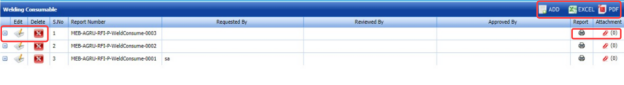
4.8.1 Add a Welding Consumable
If you want to add a welding consumable, do the following steps,
-
Click
 (ADD button) in the Welding Consumable page. See Fig 4.8.
A new window opens to add a welding consumable.
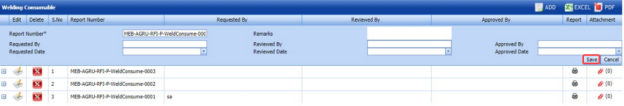
 Note: A report number for a new welding consumable list will be updated automatically in the Report Number / Rev box.
 -
In the Remarks box, enter your remarks if any.
- In the Supplier box, enter the name of a supplier of welding consumables.
- In the Requested By box, enter the name of a person who has requested the welding consumable.
- In the Reviewed By box, enter the name of a person who has reviewed the welding consumable.
- In the Approved By box, enter the name of a person who has approved the welding consumable.
- In the Requested Date box, choose the prepared date of the welding consumable.
- In the Reviewed Date box, choose the reviewed date of the welding consumable.
- In the Approved Date box, choose the approved date of the welding consumable list.
- Click Save.
The welding consumable is successfully added. Once you have added the welding consumable, you must add the details of welding consumable.


4.8.2 Add Welding Consumable Details for Added Consumable
If you want to add the details of welding consumables for the added consumable, do the following,
-
Click
 (Add icon) for the respective welding consumable. See Fig 4.8.
A new window opens to add the welding consumable details.

- In the Date box, select the date.
- In the Product Description box, enter the product description detail.
-
In the Brand box, enter the brand name of welding consumable.
- In the Type box, enter the type of the welding consumable.
- In the Diameter box, enter the diameter of the welding consumable.
- In the Batch No box, enter the batch number of the welding consumable.
- In the Certificate No box, enter the certificate number.
- In the Report No box, enter the report number.
- In the Qty in Kg box, enter the quantity of the welding consumable.
- Click Save.

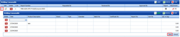
4.8.3 Print a Welding Consumable Report
If you want to print a welding consumable report, click  (print icon) in the Report column of the Welding Consumable page. See Fig 4.8.
4.8.4 Attach a File into a Welding Consumable
If you want to attach any file with an existing MVR inspection request listed in the MVR Inspection Request page, you can attach the file by using  (Attach icon) in the Attachment column. To know how to attach, follow the procedures given in the topic “Attach a file into P&ID”.
4.8.5 Edit a Welding Consumable
If you want to edit any existing welding consumable in the Welding Consumable page, do the following,
-
Click
 (Edit icon)in the Edit column for the respective welding consumable. See Fig 4.8.
A new window opens and shows the added details of the welding consumable.
- Click any box where you want to edit the details, and then edit the details in the respective box.
- Click Save.

4.8.6 Delete a Welding Consumable
If you want to delete any specific welding consumable, you can use  (Delete icon) provided in the Delete column of the Welding Consumable page, See Fig 7.8. To know how to delete, see the topic, “Delete P&ID”.
4.8.7 Export Welding Consumable
You can export a list of welding consumable added in the Welding consumable page in the pdf and excel formats by using  (PDF button) and
  (Excel button). To know how to export, see the topic, “Export P&ID list”.
4.9 Import from Excel – Materials
The Import from Excel – Materials tab helps you to upload various date related to materials for all fields included in the Materials menu instead of uploading data for each field individually.
If you want to import material data for different fields, do the following,
-
Click the Import from Excel – Materials tab in the Materials menu.
The File Upload page opens.
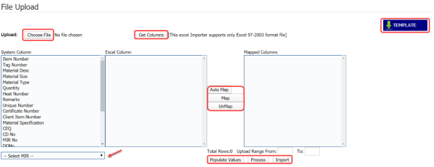
-
Download a template by using the
 (TEMPLATE button) to enter the details of data.
An excel worksheet will be downloaded.
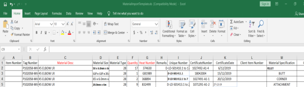
-
Enter the relevant details in the respective column of the excel worksheet based on the columns listed in the System Column field.
-
Click
 (Choose File button).
Once the file has been uploaded successfully, you receive a message, “Successfully uploaded"
-
Click
 (Get Columns button).
The columns added in the excel worksheet will be listed in the Excel Column field. The system automatically maps the Required Columns to Import field and the Excel Column field and displays in the Mapped Columns field.
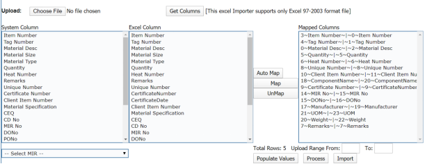
-
If you want to map any columns or to un-map any mapped columns, select the respective columns and then click
 (Map button) and
  (UnMap button) accordingly.
 -
If you want to upload the data for specific MIR, select the respective MIR from the drop-down list otherwise select BULK IMPORT.

-
Once you have completed the mapping and un-mapping of columns, in the Upload Range From and To fields, enter the range of rows you want to upload from the excel worksheet.
 Note: In the Total Rows field, the system indicates the total number of rows filled in the excel worksheet.
 Tip: You must enter the upload starting range as two in the Upload Range From field because a first row in the excel worksheet is having heading of the columns.
 -
Click
 (Populate Value button).
The data added in the excel worksheet will be populated.
-
Click
 (Process button).
Once you have clicked the Process button, the system processes the columns and displays in the Excel Import page.

-
Click
 (Import button) to import the data added in the excel worksheet.
The data will be successfully imported.
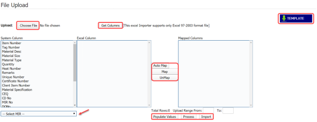

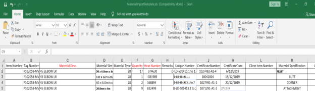


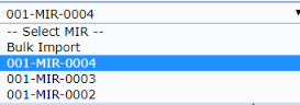


4.10 Material Traceability Record (MTR)
The Material Traceability Record tab in the Materials menu helps you to view the MTR for the piping project. The MTR lists material specification, material size, joint number, unique number, and MIR number. To view the MTR,
-
Click Material Traceability Record in the Materials menu.
The Piping Material Traceability Record page opens.

- In the ISO Drawing Number box, select an ISO drawing from a drop-down list.
The Piping Material Traceability Record page shows the material details based on the selected ISO drawing number.
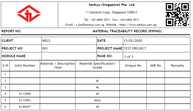
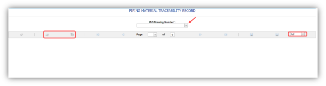

4.10.1 Print an MTR
If you want to print an MTR, use  and
and  (print icons) provided in the Piping Material Traceability Record page.
-
If you want to print the current page of the MTR, click
 (print icon including the page number).
 -
If you want to print all the pages of the MTR, click
 (print icon).


4.10.2 Export an MTR
You can export the MTR report in various formats by using the option  provided in the upper right corner of the Piping Material Traceability Record page.
4.11 Purchase Order (PO) Summary Report
The PO Summary Report tab in the Material menu used to view the purchase order summary report. To view the PO summary report,
-
Click PO Summary Report in the Material menu.
The PO Summary Report page opens.

Figure 7.11: PO Summary Report page
-
In the PO No box, select the PO number.
-
In the From Date and To Date boxes, select the from and to dates to view the PO summary report.
- Click Search.
The page shows the summary report for the purchase order.
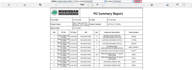
4.11.1 Print a PO Summary Report
If you want to print the PO summary report, use and (print icons) provided in the DPWR page. See Fig 4.11.
-
If you want to print the current page of the PO summary report, click
 (print icon including the page number).
 - If you want to print all the pages of the PO summary report, click
 (print icon).


4.11.2 Export a PO Summary Report
You can export the PO Summary Report in various formats by using the option  provided in the upper right corner of the page.
4.12 MVR Summary by Drawing
The MVR Summary by Drawing tab in the Materials menu used to view the MVR summary report. To view an MVR summary report,
- Click MVR Summary by Drawing in the Materials menu.
The MVR Summary (Piping) page opens.
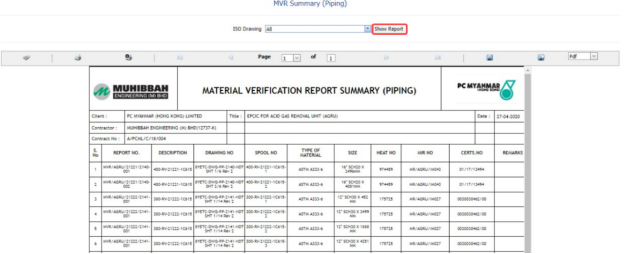
Figure 4.12: MVR Summary (Piping) page
- In the ISO Drawing box, select an ISO drawing from a drop-down list.
- Click Show Report.
The page shows the summary details for the MVR.

4.12.1 Print an MVR Summary Report
If you want to print the MVR summary report, use  and
and  (print icons) provided in the MVR Summary (Piping) page. See Fig 4.12.
- If you want to print the current page of the MVR summary report, click
 (print icon including the page number).
 - If you want to print all the pages of the MVR summary report, click
 (print icon).


4.12.2 Export an MVR Summary Report
You can export the MVR summary report in various formats by using the option  provided in the upper right corner of the MVR Summary (Piping) page.
4.13 Unique Number Usage Details
The Unique Number Usage Details tab in the Materials menu used to view the usage details of the particular unique number.
-
Click Unique Number Usage Details in the Materials menu.
The Unique Number Usage Details page opens.

Figure 4.13: Unique Number Usage Details page
- In the MIR Report Number box, enter the MIR report number.
- In the Component Name box, enter the component name.
- In the Heat Number box, enter the heat number.
- In the Unique Number box, enter the unique number.
- Click Get Details.

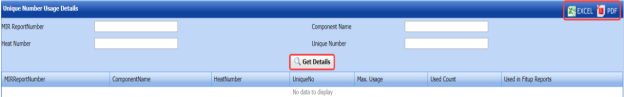
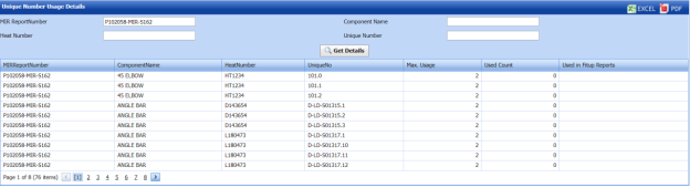
4.14 RFI Material Substitution
An RFI could be issued requesting for material substitutions if certain material is not available or cost exorbitantly high. Various subcontractors could be provided with these requests to find who has the best quality materials for the project.
You can add an RFI for material substitution by using the RFI Material Substitution tab in the Materials menu.
4.14.1 Add an RFI Material Substitution Request
If you want to add an RFI material substitution request, do the following steps,
-
Click RFI Material Substitution in the Materials menu.
The RFI Material Substitution page opens.
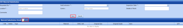
Figure 7.14: RFI Material Substitution page
- In the Requested By box, enter the name of a person who has requested the material substitution.
-
In the Sub Contractor box, select a sub-contractor from a drop-down list.
- In the Inspection Date & Time box, select the inspection date and time.
- In the Location box, enter the location name.
- In the Center box, enter the center name.
- In the Details of Work box, enter the work details.
- In the Comments box, enter your comments if any.
Before saving the added material substitution request, you must add the material substitution detail.
-
Click
 (ADD button) in the Material Substitution Detail
 - In the Type box, select the type of material substitution.
-
In the Material box, enter the name of the material.
- In the DWG. Ref box, enter the drawing reference number.
- In the Original Size box, enter the original size of the material.
- In the Original Grade box, enter the original grade of the material.
- In the Item box, select an item.
- In the QTY box, enter the quantity of the material.
- Click Save.
The material substitution details will be added and listed in the Material Substitution Detail window.

If you want to add the proposed material substitution detail,
-
Click
 (Add icon) in the Material Substitution Detail window.
-
Click
 (ADD button).
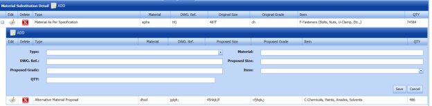
- Enter the details of proposed material substitution.
-
Click Save.
The request for material substitution will be added and listed in the View RFI Material Substitution page.


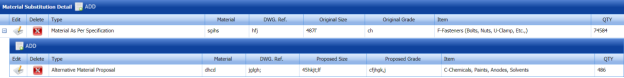


4.15 View RFI Material Substitution
The View RFI Material Substitution tab helps you to view and edit the material substitution request, which is added by using the RFI Material Substitution tab. This tab also allows you to add a new material substitution request.
- Click View RFI Material Substitution in the Materials menu.
The View RFI Material Substitution page opens with a list of added material substitution requests.

Figure 4.15: View RFI Material Substitution page
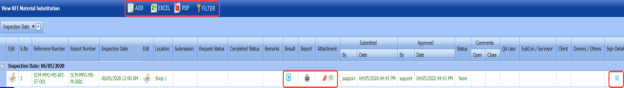
4.15.1 Add an RFI Material Substitution Request
If you want to add a material substitution request, do the following steps,
-
Click
 (ADD button) in the View RFI Material Substitution page.
The system redirects you to a new page to add a new material substitution request. To know how to add a material substitution request, See the topic, “Add an RFI Material Substitution”.

Once you have added the material substitution request, you must submit the added request to perform material substitution inspection.
4.15.2 Edit an RFI Material Substitution Request
If you want to edit any existing material substitution inspection request in the View RFI Material Substitution page, do the following,
-
Click
 (Edit icon) in the Edit column for the respective material substitution inspection request. See Fig 4.15.
The RFI Material Substitution page opens with the details of the selected material substitution inspection request.
- Click any box where you want to edit the details, and then edit the details in the respective box.
- Click Save.

4.15.3 Submit and Approve an RFI Material Substitution Request
Once you have added the material substitution inspection request, the Submission column in the View RFI Material Substitution page is appeared with  (Submit and Reject icons).
- If you want to submit the material substitution inspection request, click
 (Submit icon) in the Submission Otherwise click
  (Reject icon) to reject the request.
Once you have submitted the material substitution inspection request, the Request Status column in the View RFI Material Substitution page is appeared with (Approve and Reject icons).
- If you want to approve the material substitution inspection request, click
 (Approve icon) in the Request Status Otherwise click
  (Reject icon) to reject the request.


4.15.4 Add Results of Material Substitution Inspection
After completing the material inspection for the added request, you can add the inspection result details. To add results, do the following steps,
- Click
 (Add icon) in the Results column of the respective request.
The Result window opens with the details of proposed and original materials.

- In the Result column, select the result of each material from the given result options in the drop-down list.
- In the Remarks column, enter your remarks if any.
- Click Approve All & Save.


4.15.5 View a Material Substitution Report
If you want to view a material substitution report, click  (print icon) provided in the Print column of the View RFI Material Substitution page. See Fig 7.15.
4.15.6 Attach a File into an RFI Material Substitution Request
If you want to attach a file with any existing material substitution inspection request listed in the View RFI Material Substitution page, you can attach the file by using  (Attach icon) in the Attachment column. To know how to attach, follow the procedures given in the topic “Attach a file into P&ID”.
4.15.7 View Signature Details of Inspectors
You can view the sign details of the inspectors such as QA, Sub contractor, Client, and Owner, once they completed the material substitution inspection and submitted the inspection result details including their signature. To view the signature details, click (Sign icon) in the Sign Details column in the View RFI Material Substitution page.
4.15.8 Export an RFI Material Substitution List
You can export a list of material substitution requests added in the View RFI Material Substitution page in both the pdf and excel formats by using  (PDF button) and
  (Excel button). To know how to export, see the topic, “Export P&ID list”.
4.15.9 Filter an RFI Material Substitution Request
If you want to filter any specific material substitution inspection request in the View RFI Material Substitution page, you can use  (FILTER button) located on the View RFI Material Substitution page. To know how to filter, see the topic, “Filter P&ID”.
4.16 Material Verification Report (MVR) (Unique Numbers)
Material Inspection is nothing but validating the quality of purchased raw materials based on the set acceptance criteria before the materials are used in the piping project.
Material Inspection is nothing but validating the quality of purchased raw materials based on the set acceptance criteria before the materials are used in the piping project.
If you want to add a MIR request, do the following,
- Click Material Receiving and Inspection in the Materials menu.
The Material Verification Report page opens.
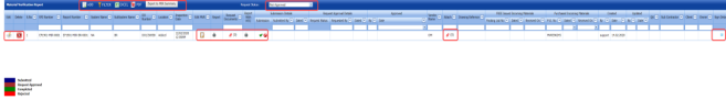
Figure 4.16: Material Verification Report page

4.16.1 Add a MIR Request
If you want to add a MIR request,
-
Click
 (ADD button) in the Material Verification Report See Fig 4.16.
A new window opens to add a MIR request.

 Note: The fields notified with a symbol (*) are mandatory. You must enter the relevant details in that fields before saving.
 Tip: A report number and a Request for Inspection (RFI) number for a new MIR will be updated automatically in the Report Number and the RFI Number boxes, respectively.
 - In the Delivery Order Number box, enter the material’s delivery order number.
- If the materials are received from a client, select the SAN Incoming Materials option, and then enter the relevant details in the respective boxes.
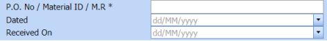
-
- In the O. No/Material ID/M. R box, enter the purchase order/material id number/ material receiving number.
- In the Dated box, choose the date of the purchase order.
- In the Received On box, select the received date of materials.
-
-
If the materials are purchased from outside, select the FREE Issued Incoming Materials option, and then enter the relevant details in the respective boxes.
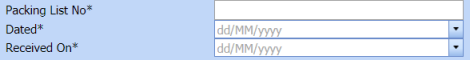
-
-
In the Packing List No box, enter the packing list number.
- In the Dated box, choose the date of packing.
- In the Received On box, choose the received date of materials.
-
-
- In the Inspection Date box, choose the date of inspection.
- In the Requested By box, enter the name of a person who has requested the MIR.
- In the Vendor Name box, enter the vendor name.
- In the Delivery Note box, enter the delivery note.
- In the Drawing Reference box, enter the reference drawing detail.
- In the Location box, enter the location name.
- In the Sub System box, select a sub system from a drop-down list.
- In the Description box, enter the description for the MIR.
- In the Bar Code box, enter the bar code of the material.
- Click Save.
The MIR request is successfully added. Once you have added the MIR request, you must add the material details for the added MIR.

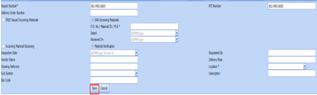


4.16.2 Add Materials for MIR
To add the details of materials for the added MIR request, do the following steps,
-
Click
 (Edit icon) of the respective MIR. See Fig 4.16.
The Add/Edit - Materials window opens.
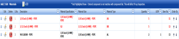
Figure 4.16.1: Add/Edit – Materials window
-
Click
 (ADD button) in the Add/Edit - Materials window.
A new window opens to add the material details.

 Note: The fields notified with a symbol (*) are mandatory. You must enter the relevant details in that fields before saving.
 - In the Material Description box, select the material from a drop-down list and enter the component details.
- In the Material Size box, select the size of the material from a drop-down list.
- In the Material Specification box, enter the material specification.
-
In the Material Type box, select the type of material.
- In the Quantity Required box, enter the required quantity of the material.
- In the Unit of Measurement (UOM) box, enter the UOM detail.
- In the Item No box, enter the item number.
- In the Material Remarks box, enter your remarks if any.
- Click Update.
The added material will be listed in the Add/Edit – Materials window.
 Note: If Add/Edit – Materials window shows the added material in the in red color means that the added component is not matched with the component list. See Fig 4.16.1.
Once you have added the material details, you must add the heat numbers for the added materials.


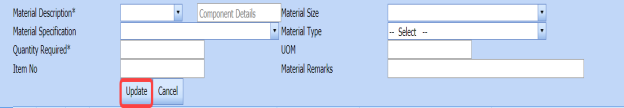


4.16.3 Add Heat/Unique numbers for materials
To add heat numbers,
- Click
 (Add icon) of the respective material in the Add/Edit - Materials See Fig 4.16.1.
The Heat Numbers window opens.
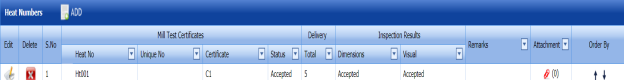
-
Click
 (ADD button) in the Heat Numbers window.
A new window opens to add a heat number.

- In the Heat Number box, select the heat number from a drop-down list.
- In the Certificates box, enter the certificate name.
- In the Plate Number/Equipment Tag Number box, enter the plate number or equipment tag number of the material.
- In the Delivery Quantity (Total) box, enter the total delivery quantity of the material.
- In the Unique Number box, enter the unique number of the material.
- In the Dimensions option, update the dimensions result by selecting Accepted or Rejected based on the inspection detail.
-
In the Visual option, update the visual result by selecting Accepted or Rejected based on the inspection detail.
- In the Mill Test Certificates (MTC) option, update the mill test certificates result by selecting Accepted or Rejected based on the inspection detail.
-
In the Remarks option, enter your remarks if any.
-
Click Update.
The heat numbers are updated. Once you have added the MIR request, you must submit the added request for inspection.


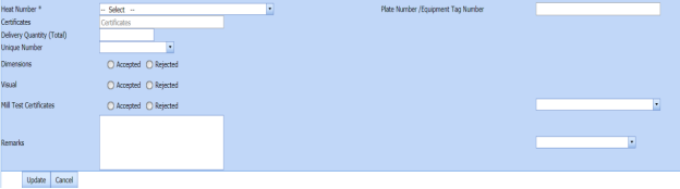
4.16.4 Submit and Approve an MIR Request
Once you have added the MIR request, the Submission column in the Material Verification Report page is appeared with  (Submit and Reject icons).
- If you want to submit the MIR request, click
 (Submit icon) in the Submission Otherwise click
  (Reject icon) to reject the request.
Once you have submitted the MIR request, the Request Status column in the Material Verification Report page is appeared with
 (Approve and Reject icons).
 -
If you want to approve the MIR request, click
 (Approve icon) in the Request Status column. Otherwise click
  (Reject icon) to reject the request.


The MIR request will be moved for MIR inspection.
4.16.5 Edit an MIR Request
If you want to edit any existing MIR request in the Material Verification Report page,
-
Click
 (Edit icon) of the respective MIR request. See Fig 4.16.
The Material Verification Report page shows the details of the selected MIR request.
- Edit the details where you want.
-
Click Save.

4.16.6 Delete an MIR Request
If you want to delete any existing MIR request in the Material Verification Report page, you can use  (Delete icon) provided in the Material Verification Report page. To know how to delete, see the topic, “Delete P&ID”.
4.16.7 Export MIR List
You can export a list of MIR requests added in the Material Verification Report page in both the pdf and excel formats by using  (PDF button) and
  (Excel button). To know how to export, see the topic, “Export P&ID list”.
4.16.8 Filter an MIR Request
If you want to filter any specific test equipment in the Material Verification Report page,
-
you can use the request status wise filter box
 provided in the upper side of the Material Verification Report page.
 - You can also use
 (FILTER button) located on the Material Verification Report To know how to filter using the Filter button, see the topic, “Filter P&ID”.


4.16.9 View a Material Receiving Inspection Report
To view a material receiving inspection report, click  (Print icon) provided in the Report column of the Material Verification Report page.
4.16.10 View a Material Test Certificate (MTC) Report
To view an MTC report, click (Print icon) provided in the Report with MTC column of the Material Verification Report page.
4.16.11 View Signature Details of Inspectors
You can view the sign details of the inspectors such as QA, Sub contractor, Client, and Owner, once they completed the MIR inspection and submitted the inspection result details including their signature. To view the signature details, click  (Sign icon) in the Sign Details column in the Material Verification Report page.
4.17 Material Receiving and Inspection (Unique Numbers)
The Material Receiving and Inspection tab in the Materials menu helps you to add an incoming material inspection report (MIR). Incoming MIR includes material name, material size, material specification, and material type.
If you want to add an incoming MIR, do the following,
- Click the Material Receiving and Inspection tab in the Materials menu.
The Incoming Material Inspection Report page opens.
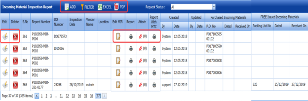
Figure 4.17: Incoming Material Inspection Report page
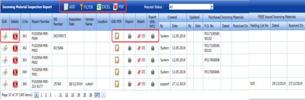
4.17.1 Add an Incoming MIR
If you want to add an incoming MIR,
-
Click
 (ADD button) in the Incoming Material Inspection Report page. See Fig 4.17.
A new window opens to add an incoming MIR.
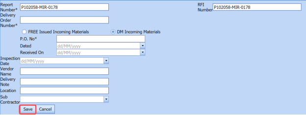
 Note: The fields notified with a symbol (*) are mandatory. You must enter the relevant details in that fields before saving.
 Tip: A report number and an Request for Inspection (RFI) number for a new MIR will be updated automatically in the Report Number and the RFI Number boxes, respectively.
 - In the Delivery Order Number box, enter the material’s delivery order number.
- If the materials are received from a client, select the DM Incoming Materials option, and then enter the relevant details in the respective boxes.
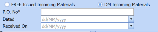
-
- In the P.O. No box, enter the purchase order number.
- In the Dated box, choose the date of the purchase order.
- In the Received On box, select the received date of materials.
-
- If the materials are purchased from outside, select the FREE Issued Incoming Materials option, and then enter the relevant details in the respective boxes.

-
- In the Packing List No box, enter the packing list number.
- In the Dated box, choose the date of packing.
- In the Received On box, choose the received date of materials.
-
- In the Inspection Date box, choose the date of inspection.
- In the Vendor Name box, enter the vendor name.
-
In the Delivery Note box, enter the delivery note.
-
In the Location box, enter the location name.
- In the Sub Contractor box, select the subcontractor name from a drop-down list.
-
Click Save.
The incoming MIR is successfully added. Once you have added the MIR, you must add the material details for the added MIR.


4.17.2 Add materials for an incoming MIR
If you want to add the details of materials for the added incoming MIR, do the following,
-
Click
 (Edit icon) in the Edit MIR column of the Incoming Material Inspection Report page. See Fig 4.17.
The Add/Edit - Materials window opens.
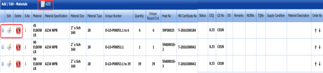
Figure 4.17.1: Add/Edit – Materials window
-
Click
 (ADD button) in the Add/Edit - Materials window.
A new window opens to add the material details.
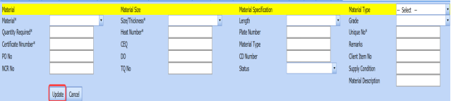
 Note: The fields notified with a symbol (*) are mandatory. You must enter the relevant details in that fields before saving.
 - In the Material box, select the name of the material from a drop-down list.
- In the Quantity Required box, enter the required quantity of the material.
- In the Certificate Number box, enter the certificate number.
- In the PO No box, enter the purchase order number.
- In the Non-Conformance Report (NCR) No box, enter the NCR number.
- In the Size/Thickness box, select the size/thickness of the received material from a drop-down list.
- In the Heat Number box, enter the heat number of the material.
- In the CEQ box, enter the CEQ number.
- In the DO box, enter the deliver order number.
- In the TQ No box, enter the TQ number.
- In the Length box, select the length of the material from a drop-down list.
- In the Plate Number box, enter the plate number of the material.
- In the Material Type box, enter the type of the material.
-
In the CD Number box, enter the CD number.
- In the Status box, select the status of the received material.
- In the Material Type box, select the type of material from a drop-down list.
- In the Grade box, select the grade of the material.
- In the Unique No box, enter the unique number of the material.
- In the Remarks box, enter your remarks if any.
- In the Client Item No box, enter the client item number.
- In the Supply Condition box, enter the supply condition details of the material.
- In the Material Description box, enter the material description.
- Click Update.
Once you have added the material details, you must add the heat numbers for the added materials.

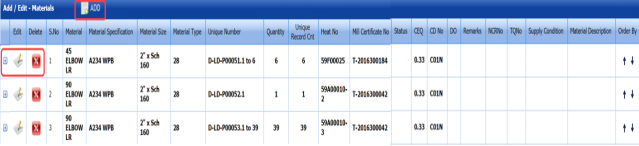


4.17.3 Add Heat Numbers
- Click
 (Add icon) of the respective material in the Add/Edit - Materials See Fig 4.17.1.
The Heat Numbers window opens.
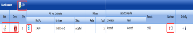
-
Click
 (ADD button) in the Heat Numbers window.
A new window opens to add a heat number.
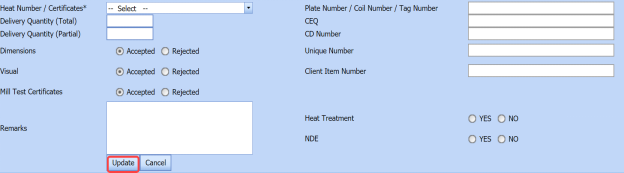
-
In the Heat Number/Certificates box, select the heat number from a drop-down list.
-
In the Plate Number/Coil Number/ Tag Number box, enter the plate number or coil number or tag number of the material.
- In the Delivery Quantity (Total) box, enter the total delivery quantity of the material.
- In the Delivery Quantity (Partial) box, enter the partial delivery quantity of the material.
- In the CEQ box, enter the CEQ number.
- In the CD Number box, enter the CD number.
- In the Unique Number box, enter the unique number of the material.
- In the Client Item Number box, enter the client item number.
- In the Dimensions option, select Accepted or Rejected based on the inspection detail.
- In the Visual option, select Accepted or Rejected based on the inspection detail.
- In the Mill Test Certificates (MTC) option, select Accepted or Rejected based on the inspection detail.
- In the Remarks option, enter your remarks if any.
-
If the heat treatment is required for the material, select YES in the Heat Treatment option. Otherwise select NO.
- In the NDE is required for the material, select YES in the NDE Otherwise select NO.
- Click Update.
Once you have added the heat numbers, you must add unique numbers for the material.

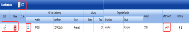

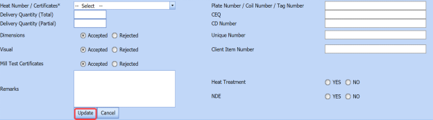
4.17.4 Add Unique Numbers
-
Click
 (Add icon) of the respective heat number in the Heat Numbers box.
The Unique Numbers box opens.
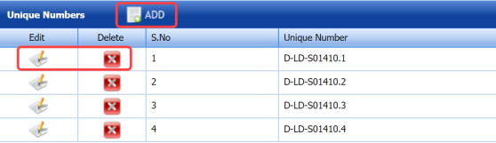
-
Click
 (ADD button) in the Unique Numbers window.
A new window opens to add a unique number.

- In the Unique Number box, enter a unique number for the respective heat number.
-
In the Original Number box, enter the original number of the material.
- In the Size box, enter the size of the material.
-
Click Update.


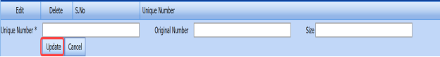
4.17.5 Print an Incoming MIR
If you want to print an incoming MIR report, click  (print icon) provided in the Report column of the Incoming Material Inspection Report page. See Fig 4.17.
4.17.6 Print a Report with MTC
If you want to print an incoming MIR report including MTC, click (print icon) provided in the Report with MTC column of the Incoming Material Inspection Report page. See Fig 4.17.
4.17.7 Attach a File into an Added Incoming MIR
If you want to attach any file with any incoming MIR listed in the Incoming Material Inspection Report page. To know how to attach, follow the procedures given in the topic “Attach a file into P&ID”.
4.17.8 Edit an Incoming MIR
If you want to edit any existing incoming MIR in the Incoming Material Inspection Report page, do the following,
-
Click
 (Edit icon)in the Edit column for the respective MIR. See Fig 4.17.
A new window opens to edit the added incoming MIR.
- Click any box where you want to edit the details, and then edit the details in the respective box.
-
Click Save.

4.17.9 Delete an Incoming MIR
If you want to delete any specific incoming MIR from the list of MIRs, you can use  (Delete icon) provided in the Delete column of the Incoming Material Inspection Report page. To know how to delete, see the topic, “Delete P&ID”.
4.17.10 Filter an Incoming MIR
If you want to filter any incoming MIR from the list of MIRs in the Incoming Material Inspection Report page,
-
you can use the request status wise filter box
 provided in the upper side of the Incoming Material Inspection Report page.
 - You can also use
 (FILTER button) located on the Incoming Material Inspection Report To know how to filter using the Filter button, see the topic, “Filter P&ID”.


4.17.11 Export Incoming MIR List
You can export a list of MIR added in the Incoming Material Inspection Report page in the pdf and excel formats by using  (PDF button) and (Excel button). To know how to export, see the topic, “Export P&ID list”.
Inspection
5.0 Inspection
5.1 RFI Fit up Request (Heat Numbers)
The RFI Fit up Request tab allows you add an RFI fit up request to check the fit-up quality of pipes and joints used in the piping project by a sub-contractor. To navigate to the RFI fit up request adding page,
- Click RFI Fit up Request in the Inspection menu.
The RFI Fit up Request page opens.
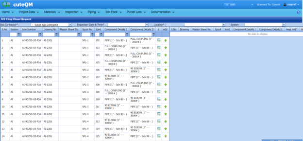
Figure 5.1: RFI Fit up Request page

5.1.1 Add an RFI Fit up Request
If you want to add an RFI fit up request, do the following steps,
-
In the Sub Contractor box, select the sub-contractor from a drop-down list.
-
In the Inspection Date and Time box, select the inspection date and time.
 Note: The inspection date should be as current date or upcoming dates. The system will not accept if you have given the previous dates. The fit up inspection date should not be later than the RFI weld visual inspection date.
 - In the Location box, select a location from a drop-down list.
- In the System box, select a system from a drop-down list.
Before saving the added fit up request, you must add joints for the fit-up request.
 Note: You can add multiple joints for one request.
The RFI Fit up Request page shows a list of joints for the corresponding line and drawing numbers including the component details. If you want to add joints for the RFI Fit up request, do the following,
- Before adding joints, click the respective
 (Add component details icon) of the joints which you want to add.
The Component – I & II box opens.

- Check and edit the details of first and second components.
-
-
Check the first and second components name. If you want to change the component, you can change the component by using a drop-down list.
- In the Material box, select the material that is the components is made with.
- Check the material specifications and grade.
- In the Diameter (MM) and Thickness (MM) boxes, select the diameter and thickness of the components from the given values.
- Click Save.
The component details will be saved successfully.
-
-
- Click
 (Add icon) of the respective joints you want to add.
The added joints will be moved and listed in the right side of the page.

- In the Heat No 1 box, enter the heat number of the first component if you know.
- In the Heat No 2 box, enter the heat number of the second component if you know.
- In the Fitter box, select the fitter from a drop-down list.
- In the WPS box, select the WPS from a drop-down list.
 Tip: If you want to remove any added joint, click
  (Remove icon) of the respective joint.
 - In the Description/Note box, enter the description for the added RFI fit up request.
- Click Save.


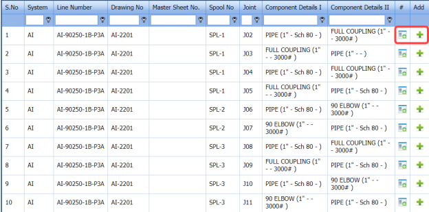

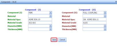

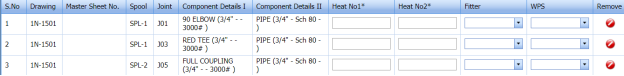


The RFI fit up request is successfully added. If you want to view the added request, navigate to View RFI Fit up.
5.2 View RFI Fit up (Heat Numbers)
The View RFI Fit up tab helps you to view and edit the RFI fit up requests, which are added by using the RFI Fit up Request tab. This tab also allows you to add a new RFI fit up request.
-
Click the View RFI Fit up tab in the Inspection menu.
The RFI Fit up Request List page opens with a list of added RFI fit up requests.
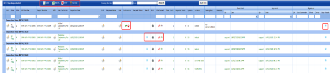
Figure 5.2: RFI Fit up Request List page
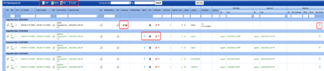
5.2.1 Add an RFI Fit up Request
If you want to add an RFI fit up request, do the following,
- Click
 (ADD button) in the RFI Fit up Request List page.
The system redirects you into RFI Fit up Request page. To know how to add an RFI fit up request, See the topic, “Add an RFI Fit up Request”.

Once you have added the RFI fit up request, you must submit the added request for inspection.
5.2.2 Add Representative for Added RFI Fit up Request
If you want to add a representative for any added RFI fit up request,
- Click
 (Edit icon) in the Representative column for the respective RFI fit up request.
The Edit Form window opens.

- In the Representative box, enter the name of a representative.
- In the Inspection Date box, select the date of inspection.
- In the Remarks box, enter your remarks if any.
- Click Save.


5.2.3 Edit an RFI Fit up Request
If you want to edit any existing RFI fit up request in the RFI Fit up Request page, do the following,
- Click (Edit icon) in the Edit column for the respective RFI fit up request. See Fig 5.2.
The RFI Fit up Visual Request page opens with the details of the selected RFI fit up request.

- Click any box where you want to edit the details, and then edit the details in the respective box.
- Click Save.
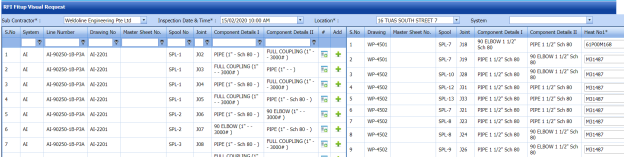
5.2.4 Submit and Approve an RFI Fit up Request
Once you have added the RFI fit up request, the Submission column in the RFI Fit up Request Lists page is appeared with (Submit and Reject icons). See Fig 5.2.
-
If you want to submit the RFI fit up request, click
 (Submit icon) in the Submission column. Otherwise click
  (Reject icon) to reject the request.
Once you have submitted the RFI fit up request, the Request Status column in the RFI Fit up Requests List page is appeared with
 (Approve and Reject icons).
 - If you want to approve the RFI fit up request, click (Submit icon) in the Request Status Otherwise click
 (Reject icon) to reject the request.


The approved request will be moved to for inspection.
5.2.5 Add Results of RFI Fit up Inspection
After completing the RFI fit up inspection for the added request, you can add the inspection result details. To add results, do the following steps,
-
Click
 (Add icon) in the Results column of the respective request.
The RFI Fit up Request List window opens with a list of joints.

- If you want to update the heat numbers for both the components, click (Edit icon) of the respective component.
The Heat Number window opens with a list of heat numbers and MIR numbers.
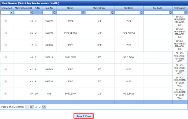
- Select the heat numbers you want to update.
- Click Save & Close.
The heat numbers will be updated successfully.
-
If you want to update the WPS number in the WPS Number column, you can change the WPS number from a drop-down list.
- Update the result for root gap by selecting Accepted or Rejected in the Root Gap column based on the inspection.
- Update the result for straight/ alignment by selecting Accepted or Rejected in the Strgt/Align column based on the inspection.
- In the Edge Prep column, select the type of the edge preparation from a drop-down list.
- In the Result column, update the RFI fit up inspection result by selecting Pending, Accepted, Rejected, or Cancelled.
- In the Remarks column, enter you remarks if any.
 Note: If you want to attach any document to add more information about the inspection results, click (Attach icon) and attach your document.

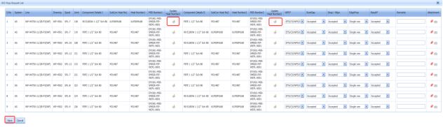
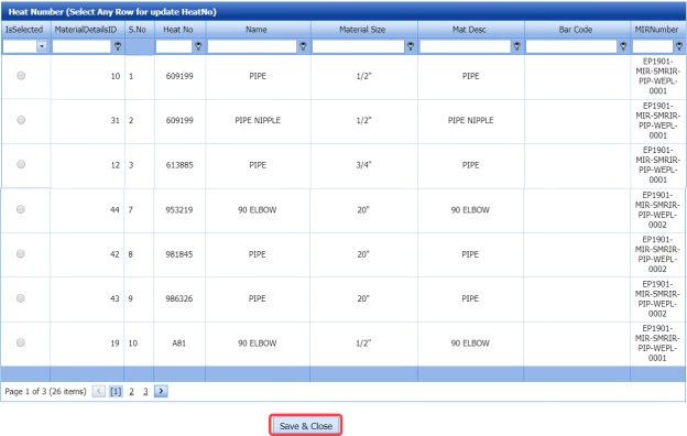

5.2.6 View an RFI Fit up Report
If you want to view an RFI fit up report, click  (print icon) provided in the Report column of the RFI Fit up Requests List page. See Fig 5.2.
5.2.7 View Signature Details of Inspectors
You can view the sign details of the inspectors such as QA, Sub contractor, Client, and Owner, once they completed the RFI fit up inspection and submitted the inspection result details including their signature. To view the signature details, click (Sign icon) in the Sign Details column in the RFI Fit up Requests List page.
5.2.8 Bulk Print the RFI Fit up Reports
If you want to print all the RFI fit up reports added in the RFI Fit up Requests List page together, click  (Bulk Print button). The Report page shows all the RFI fit up reports together.
5.2.9 Attach a File into an RFI Fit up Request
If you want to attach a file with any existing RFI fit up request listed in the RFI Fit up Requests List page, you can attach the file by using  (Attach icon) in the Attachment column. To know how to attach, follow the procedures given in the topic “Attach a file into P&ID”.
5.2.10 Export RFI Fit up Request List
You can export a list of RFI fit up requests added in the RFI Fit up Requests List page in both the pdf and excel formats by using  (PDF button) and
  (Excel button). To know how to export, see the topic, “Export P&ID list”.
5.2.11 Filter an RFI Fit up Request
If you want to filter any specific RFI fit up request in the RFI Fit up Requests List page,
- you can use the filter box
 provided in the upper side of the RFI Fit up Requests List To filter the any specific RFI fit up request, select the Drawing Number and Date in the boxes and click Search.

- you can use
 (FILTER button) located on the RFI Fit up Requests List To know how to filter, see the topic, “Filter P&ID”.

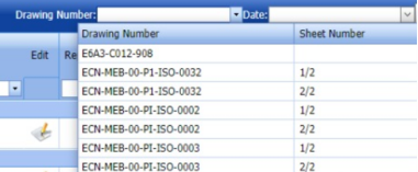

5.3 RFI Weld VI Request (Heat Numbers)
The RFI Weld VI Request tab in the Inspection menu allows you to add an RFI weld VI request to perform visual inspection of welded pipes and joints used in the piping project. To navigate to the RFI weld VI request adding page,
-
Click RFI Weld VI Request in the Inspection menu.
The RFI Weld Visual Request page opens.
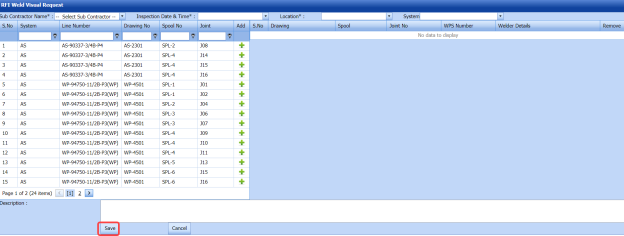
Figure 5.3: RFI Weld Visual Request page

5.3.1 Add an RFI Weld VI Request
If you want to add an RFI weld VI request, do the following steps,
- In the Sub Contractor Name box, select the name of a sub-contractor from a drop-down list.
- In the Inspection Date and Time box, select the inspection date and time.
 Note: The inspection date should be as current date or upcoming dates. The system will not accept if you have given the previous dates.
 - In the Location box, select a location from a drop-down list.
- In the System box, select a system from a drop-down list.
Before saving the added weld VI request, you must add joints for the weld VI request.
 Note: You can add multiple joints for one request.
The RFI Weld Visual Request page shows a list of joints for the corresponding line and drawing numbers including the spool number. If you want to add joints for the RFI weld VI request, do the following steps,

-
Click
 (Add icon) of the respective joints you want to add.
The added joints will be moved and listed in the right side of the page.
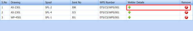
- Update the welder details by using
 (Add icon) provided in the Welder Details
-
- Click
 (Add icon) of the respective joint number.
The Welder- Weld Layer- Weld Process window opens.
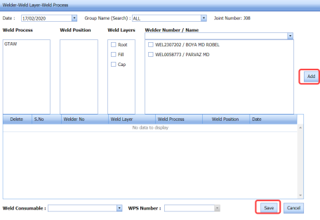
- In the Date box, select the date.
- In the Group Name box, select the group name from a drop-down list.
- In the Weld Process field, select a weld process.
- In the Weld Position field, select the welding position.
- In the Weld Layers field, select the weld layers you want add.
- In the Welder Number/ Name field, select the welders you want to add.
- Click Add.
The selected welders will be added and listed in the below table. See the above figure.
- In the Weld Consumable box, select the weld consumable from a drop-down list.
- In the WPS Number box, select the WPS number from a drop-down list.
- Click Save.
 Tip: If you want to remove any added joint, click (Remove icon) of the respective joint.
 - In the Description box, enter the description for the added RFI weld VI request.
- Click Save.
The RFI weld VI request is successfully added. If you want to view the added request, navigate to View RFI Weld VI.
- Click
-


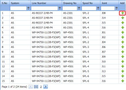


5.4 View RFI Weld VI (Heat Numbers)
The View RFI Weld VI tab helps you to view and edit the RFI weld VI request, which is added by using the RFI Weld VI Request tab. This tab also allows you to add a new RFI weld VI request.
-
Click the View RFI Weld VI tab in the Inspection menu.
The RFI Weld Visual Requests List page opens with a list of added RFI weld VI requests.

Figure 5.4: RFI Weld Visual Requests List page
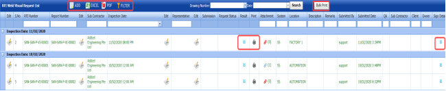
5.4.1 Add an RFI Weld VI Request
If you want to add an RFI weld VI request, do the following,
-
Click
 (ADD button) in the RFI Weld Visual Requests List page.
The system redirects you into RFI Weld Visual Request page. To know how to add an RFI weld VI request, See the topic, “Add an RFI Weld VI Request”.

Once you have added the RFI weld VI request, you must submit the added request for weld visual inspection.
5.4.2 Add Representative for Added RFI Weld VI Request
If you want to add a representative for any added RFI weld VI request,
-
Click
 (Edit icon) in the Representative column for the respective RFI weld VI request.
The Edit Form window opens.

- In the Representative box, enter the name of a representative.
- In the Inspection Date box, select the date of inspection.
- In the Remarks box, enter your remarks if any.
- Click Save.

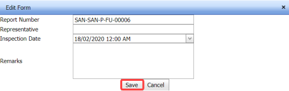
5.4.3 Edit an RFI Weld VI Request
If you want to edit any existing RFI weld VI request in the RFI Weld Visual Requests List page, do the following,
- Click
 (Edit icon) in the Edit column for the respective RFI weld VI request. See Fig 5.4.
The RFI Weld Visual Request page opens with the details of the selected RFI weld VI request.
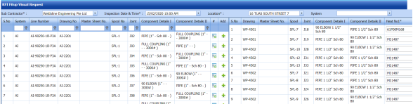
- Click any box where you want to edit the details, and then edit the details in the respective box.
- Click Save.


5.4.4 Submit an RFI Weld VI Request
Once you have added the RFI weld VI request, the Request Status column in the RFI Weld Visual Requests List page is appeared  with (Submit and Reject icons). See Fig 5.4.
- If you want to submit the RFI weld VI request, click
 (Submit icon) in the Request Status Otherwise click
  (Reject icon) to reject the request.


The submitted request will be moved to for RFI weld visual inspection.
5.4.5 Add Results of RFI weld Visual Inspection
After completing the RFI weld visual inspection for the added request, you can add the inspection result details. To add results, do the following steps,
- Click
 (Add icon) in the Results column of the respective request.
The RFI Weld Visual Request List window opens with a list of joints added for the particular request.
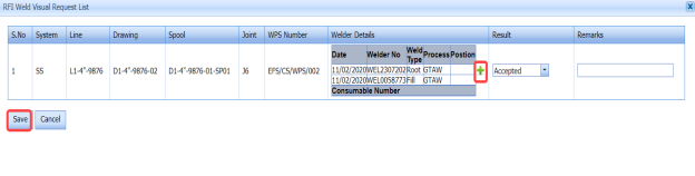
- If you want to update the welder details, click
 (Add icon) of the respective joint.
The Welder-Weld Layer-Weld Process window opens.
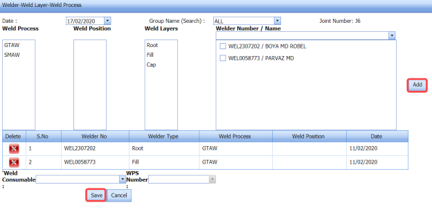
 Note: If you want to delete any added weld, click (Delete icon) of the respective welder.
 -
- In the Date box, select the date.
- In the Group Name box, select the group name from a drop-down list.
- In the Weld Process field, select a weld process.
- In the Weld Position field, select the welding position.
- In the Weld Layers field, select the weld layers you want add.
- In the Welder Number/ Name field, select the welders you want to add.
- Click Add.
The selected welders will be added and listed in the below table. See the above figure.
- In the Weld Consumable box, select the weld consumable from a drop-down list.
- In the WPS Number box, select the WPS number from a drop-down list.
- Click Save.
-
- In the Result column, select the result for each joint from the given result options in the drop-down list.
- In the Remarks box, enter your remarks if any.
- Click Save.


5.4.6 View an RFI Weld VI Report
If you want to view an RFI weld VI report, click (print icon) provided in the Report column of the RFI Weld Visual Requests List page. See Fig 5.4.
5.4.7 View Signature Details of Inspectors
You can view the sign details of the inspectors such as QA, Sub contractor, Client, and Owner, once they completed the RFI weld visual inspection and submitted the inspection result details including their signature. To view the signature details, click (Sign icon) in the Sign Details column in the RFI Weld Visual Requests List page.
5.4.8 Bulk Print RFI Weld VI Reports
If you want to print all the RFI weld VI reports added in the RFI Weld Visual Requests List page together, click  (Bulk Print button). The Report page shows all the RFI weld VI reports together.
5.4.9 Attach a File into an RFI Weld VI Request
If you want to attach a file with any existing RFI weld VI request listed in the RFI Weld Visual Requests List page, you can attach the file by using  (Attach icon) in the Attachment column. To know how to attach, follow the procedures given in the topic “Attach a file into P&ID”.
5.4.10 Export RFI Weld VI Request List
You can export a list of RFI weld VI requests added in the RFI Weld Visual Requests List page in both the pdf and excel formats by using  (PDF button) and
  (Excel button). To know how to export, see the topic, “Export P&ID list”.
5.4.11 Filter an RFI Weld VI Request
If you want to filter any specific RFI weld VI request in the RFI Weld Visual Requests List page,
- you can use the filter box
 provided in the upper side of the RFI Weld Visual Requests List To filter the any specific RFI weld VI request, select the Drawing Number and Date in the boxes and click Search.

-
you can use
 (FILTER button) located on the RFI Weld Visual Requests List page. To know how to filter, see the topic, “Filter P&ID”.

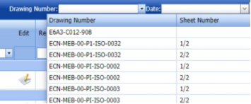

5.5 NDT Inspection Request
The NDT Inspection Request tab in the Inspection menu helps you to add an NDT inspection request to perform an NDT inspection. To navigate to the NDT inspection request adding page,
- Click NDT Inspection Request in the Inspection menu.
The NDT Inspection Request page opens.
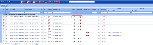
Figure 5.5: NDT Inspection Request page
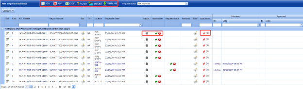
5.5.1 Add an NDT inspection request
If you want to add an NDT inspection request, do the following
-
Click
 (ADD button) in the NDT Inspection Request page.
A new page opens to add an NDT inspection request.

Figure 5.5: NDT Inspection Request page
 Note: The fields notified with a symbol (*) are mandatory. You must enter the relevant details in that fields before saving.
 -
In the Requested By box, enter the name of person who has requested for the NDT inspection.
- In the To box, select the name of a sub-contractor from a drop-down list.
- In the Description/ Spec. Ref. No box, enter the description for the request.
- In the Inspection Date & Time box, select the date of inspection.
- In the Location box, enter the location where the inspection to be done.
- In the Requisition box, enter the requisition detail.
- In the Longitudinal box, enter the longitudinal value.
- In the Drawing No box, select the drawing number from a drop-down list.
- In the Designation box, enter the designation detail.
- In the Cost Centre box, enter the cost centre detail
- In the PWHT Request Type box, select the PWHT request type from a drop-down list.
- In the System box, select a system from a drop-down list.
- In the NDT Type box, select the type of NDT you want to add.
Before saving the added NDT request, you must add joints. You can add multiple joints for one NDT inspection request.
 Note: The page shows a list of added joints. If you want to view the joints for the specific ISO drawing, select the respective ISO drawing from a drop-down list.
 - Click
 (Add icon) of the respective joint which you want to add.
The added joints will be moved to the right side of the page.
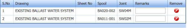
- In the Remarks box, enter your remarks if any.
- Click Save NDT Request.
The added NDT inspection request will be listed in the NDT Inspection Request page.

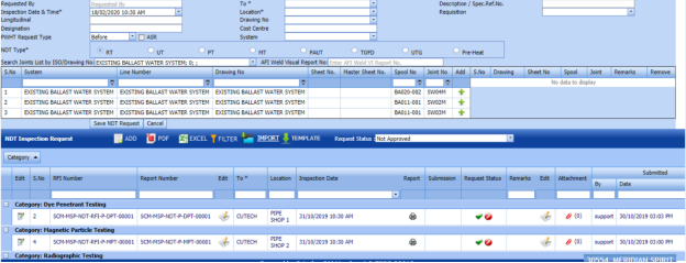


5.5.2 Edit an NDT Inspection Request
If you want to edit any existing NDT inspection request in the NDT Inspection Request page, do the following steps,
- Click
 (Edit icon) in the Edit column for the respective NDT request. See Fig 5.5.
The NDT Inspection Request page opens with the details of the selected NDT inspection request.
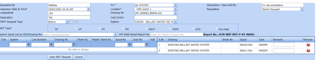
- Click any box where you want to edit the details, and then edit the details in the respective box.
- Click Save.


5.5.3 Submit and Approve an NDT Inspection Request
Once you have added the NDT inspection request, the Submission column in the NDT Inspection Request page is appeared with  (Submit and Reject icons). See Fig 5.5.
- If you want to submit the NDT inspection request, click
 (Submit icon) in the Submission Otherwise click
  (Reject icon) to reject the request.
Once the NDT inspection request has been submitted, the Request Status column in the NDT Inspection Request page is appeared with
 (Approve and Reject icons).
 - If you want to accept the NDT inspection request, click
 (Approve icon) in the Request Status Otherwise click
  (Reject icon) to reject the request.
The approved request will be moved to NDT inspection.


5.5.4 View an NDT Inspection Report
If you want to view an NDT inspection report, click  (print icon) provided in the Report column of the NDT Inspection Request page. See Fig 5.5.
5.5.5 Attach a File into an NDT Inspection Request
If you want to attach a file with any existing NDT inspection request listed in the NDT Inspection Request page, you can attach the file by using  (Attach icon) in the Attachment column. To know how to attach, follow the procedures given in the topic “Attach a file into P&ID”.
5.5.6 Export NDT Inspection Request List
You can export a list of NDT inspection requests added in the NDT Inspection Request page in both the pdf and excel formats by using  (PDF button) and
  (Excel button). To know how to export, see the topic, “Export P&ID list”.
5.5.7 Filter an NDT Inspection Request
If you want to filter any specific NDT inspection request in the NDT Inspection Request page,
-
you can use the filter box
 provided in the upper side of the NDT Inspection Request page. To filter the any specific NDT inspection request, select the request status in the Request Status box.
 - you can use
 (FILTER button) located on the NDT Inspection Request To know how to filter, see the topic, “Filter P&ID”.


5.5.8 Import Multiple NDT Inspection Requests
If you want to import multiple NDT inspection requests together, do the following,
-
Click
 (TEMPLATE button). See Fig 5.5.
An excel worksheet will be downloaded with a predefined template to enter the details of NDT inspection requests.

-
Enter the required NDT inspection request details in the respective columns of the excel worksheet.
- Once you have added the NDT inspection request details in the excel worksheet, save the excel worksheet on your computer.
- Click
 (IMPORT button). See Fig 5.5.
A new window opens for importing the excel worksheet saved on your computer.

-
Click
 (Browse button) to select the excel worksheet to be uploaded.
 -
Select the excel worksheet you want to upload from your computer.
- Click
 (Upload button) to export the NDT inspection request that are included in the excel worksheet.

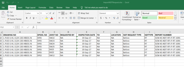


The details of the NDT inspection request in the worksheet will be displayed in the NDT Inspection Request page.
5.6 NDT Job Order
The NDT Job Order tab in the Inspection menu allows you to add a job order for a specific NDT-contractor to carry out the NDT inspection. Once you have added the job order, you can add the NDT request including the quantity and schedule date to complete the NDT inspection.
-
Click NDT Job Order in the Inspection menu.
The Job Order page opens.
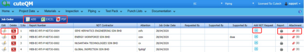
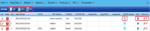
Figure 5.6: Job Order page


5.6.1 Add an NDT Job Order
If you want to add an NDT job order, do the following steps,
-
Click
 (ADD button) in the Job Order page. See Fig 5.6.
A new window opens to add an NDT job order.
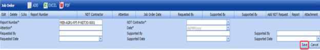
 Note: The fields notified with a symbol (*) are mandatory. You must enter the relevant details in that fields before saving.
 Tip: A report number for a new job order will be updated automatically in the Report Number box.
 - In the NDT Contractor box, select the name of an NDT contractor from a drop-down list.
- In the Attention box, enter any note if you want for attention.
- In the Date box, select the date of adding an NDT job order.
-
In the Requested By box, enter the name of a person who has requested for an NDT job order.
- In the Requested Date box, select the requested date of an NDT job order.
- In the Supported By boxes, enter the name of a project lead and a HOD, respectively.
- In the Supported Date box, select the supported date of an NDT job order.
- Click Save.
The NDT job order is successfully added.


5.6.2 Add an NDT Job Request
To add an NDT job request,
- Click
 (Add icon) of the respective job order in the Add NDT Request column of the Job Order See Fig 5.6.
A new window shows a list of added NDT request.
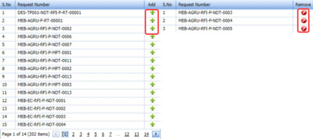
- If you want to add any request, click
 (Add icon) of the respective request.
The added NDT request will be assigned under the respective job order.
- If you want to delete any request, click
 (Delete icon) of the respective request.


5.6.3 Attach a File into an NDT Job Order
If you want to attach any file with any NDT job order listed in the Job Order page, you can attach the file by using  (Attach icon) in the Attachment column. To know how to attach, follow the procedures given in the topic “Attach a file into P&ID”.
5.6.4 View an NDT Job Order Report
If you want to view an NDT job order report, click  (print icon) provided in the Report column of the Job Order page. See Fig 5.6.
5.6.5 Edit an NDT Job Order
If you want to edit any existing NDT job order in the Job Order page, do the following,
- Click
 (Edit icon) in the Edit column for the respective NDT job order. See Fig 5.6.
A new window opens with the added details of NDT job order to edit the job order.
-
Click any box where you want to edit the details, and then edit the details in the respective box.
- Click Save.

5.6.6 Delete an NDT Job Order
If you want to delete any specific NDT job order, you can use  (Delete icon) provided in the Delete column of the Job Order page, See Fig 8.6. To know how to delete, see the topic, “Delete P&ID”.
5.6.7 Export NDT Job Order List
You can export a list of NDT job order added in the Job Order page in the pdf and excel formats by using  (PDF button) and
  (Excel button). To know how to export, see the topic, “Export P&ID list”.
5.7 Spool Release Inspection Request
The Spool Release Request tab in the Inspection menu helps you to add a spool release request. To navigate to the spool release inspection request adding page,
- Click Spool Release Request in the Inspection menu.
The Spool Release Inspection Request page opens.

Figure 5.7: Spool Release Inspection Request page
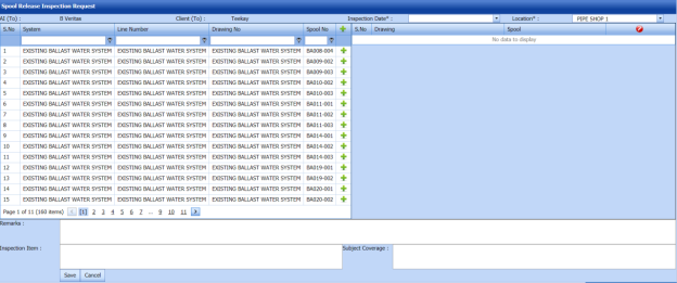
5.7.1 Add a Spool Release Inspection Request
If you want to add a spool release inspection request, do the following steps in the Spool Release Inspection Request page, See Fig 5.7.
- In the Inspection Date box, select the date of spool inspection.
- In the Location box, select the location where the spool inspection to be performed.
Before saving the added spool release inspection request, you must add spools. You can add multiple spools for one spool release inspection request.
 Note: The page shows a list of added spools. If you want to view the specific spools, use the filter options provided in the System, Line Number, Drawing Number, and Spool Number columns.
 - Click
 (Add icon) of the respective spool which you want to add.
The added spools will be moved to the right side of the page.

-
In the Remarks box, enter your remarks if any.
- In the Inspection Item box, enter the details of inspection items.
- In the Subject Coverage box, enter the details of subject coverage.
- Click Save.


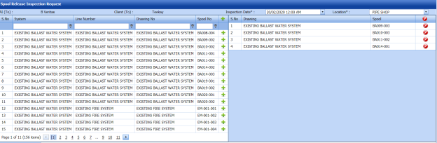
The spool release request will be added and listed in the View Spool Release page.
5.8 View Spool Release
The View Spool Release tab helps you to view and edit the spool release inspection request, which is added by using the Spool Release Inspection Request tab. This tab also allows you to add a new spool release request.
-
Click View Spool Release in the Inspection menu.
The Spool Release List page opens with a list of added spool release requests.
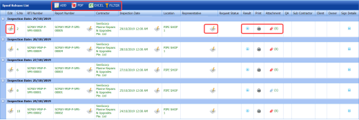
Figure 5.8: Spool Release List page

5.8.1 Add a Spool Release Inspection Request
If you want to add a spool release request, do the following steps,
-
Click
 (ADD button) in the Spool Release List page.
The system redirects you into Spool Release Inspection Request page. To know how to add a spool release inspection request, See the topic, “Add a Spool Release Inspection Request”.

Once you have added the spool release request, you must submit the added request to perform inspection in the piping spool.
5.8.2 Add Representative for Added Spool Release Inspection Request
If you want to add a representative for any added spool release request,
- Click
 (Edit icon) in the Representative column for the respective spool release request.
The Edit Form window opens.

- In the Inspection Date box, select the date of inspection.
- In the Representative box, enter the name of a representative.
- Click Save.


5.8.3 Edit a Spool Release Inspection Request
If you want to edit any existing spool release request in the Spool Release List page, do the following,
- Click
 (Edit icon) in the Edit column for the respective spool release request. See Fig 5.8.
The Spool Release Inspection Request page opens with the details of the selected spool release request.

- Click any box where you want to edit the details, and then edit the details in the respective box.
-
Click Save.

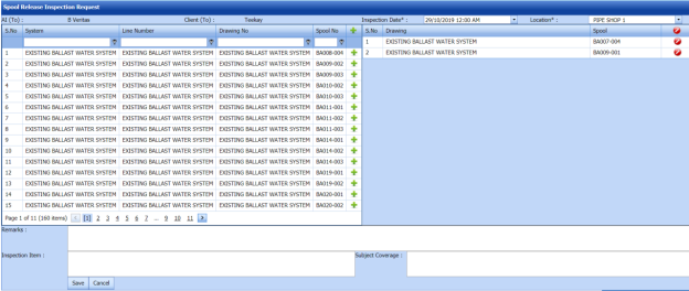
5.8.4 Submit a Spool Release Inspection Request
Once you have added the spool release request, the Request Status column in the Spool Release List page is appeared with  (Submit and Reject icons). See Fig 5.8.
- If you want to submit the spool release request, click
 (Submit icon) in the Request Status Otherwise click
  (Reject icon) to reject the request.
The submitted request will be moved to for spool inspection.


5.8.5 Add Results of Spool Release Inspection
After completing the spool release inspection for the added request, you can add the inspection result details. To add results, do the following steps,
-
Click
 (Add icon) in the Results column of the respective request.
The Spool Release List window opens with a list of spools added for the particular request.
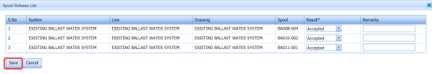
-
In the Result column, select the result for each spool from the given result options in the drop-down list.
- In the Remarks box, enter your remarks if any.
- Click Save.


5.8.6 View a Piping Spool Release Report
If you want to view a piping spool release report, click (print icon) provided in the Print column of the Spool Release List page. See Fig 5.8.
5.8.7 Attach a File into a Spool Release Inspection Request
If you want to attach a file with any existing spool release request listed in the Spool Release List page, you can attach the file by using  (Attach icon) in the Attachment column. To know how to attach, follow the procedures given in the topic “Attach a file into P&ID”.
5.8.8 View Signature Details of Inspectors
You can view the sign details of the inspectors such as QA, Sub contractor, Client, and Owner, once they completed the spool release inspection and submitted the inspection result details including their signature. To view the signature details, click  (Sign icon) in the Sign Details column in the Spool Release List page.
5.8.9 Export Spool Release Inspection Request List
You can export a list of spool release requests added in the Spool Release List page in both the pdf and excel formats by using (PDF button) and
  (Excel button). To know how to export, see the topic, “Export P&ID list”.
5.8.10 Filter a Spool Release Inspection Request
If you want to filter any specific spool release request in the Spool Release List page, you can use (FILTER button) located on the Spool Release List page. To know how to filter, see the topic, “Filter P&ID”.
5.9 Inspection Release Note
The Inspection Release Note tab in the Inspection menu helps you to add an inspection release note. To navigate to the inspection release note adding page,
-
Click Inspection Release Note in the Inspection menu.
The Inspection Release Note page opens.
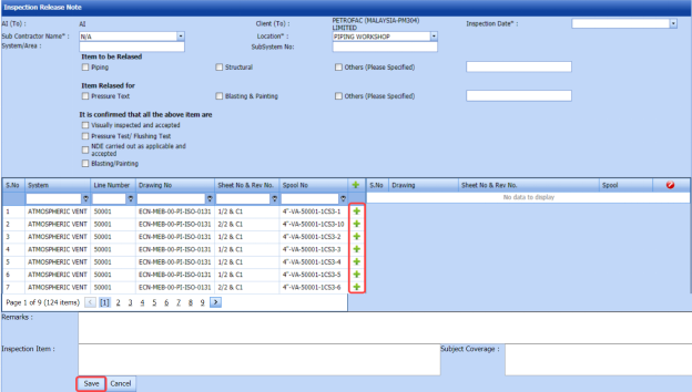
Figure 5.9: Inspection Release Note page
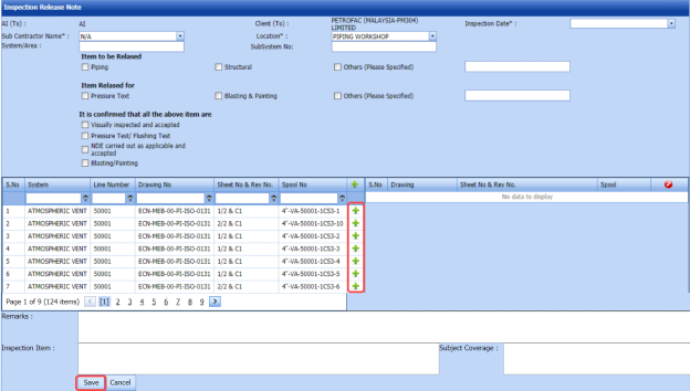
5.9.1 Add an Inspection Release Note
If you want to add an inspection release note, do the following steps,
-
In the Inspection Date box, select the date of inspection. See Fig 5.9.
- In the Sub Contractor Name box, select a sub-contractor from a drop-down list.
- In the Location box, select a location where the inspection to be held.
- In the System/Area box, enter the name of area/system.
- In the Sub System No box, enter the sub system number.
-
In the Item to be Released field, select the detail of the item to be released that is whether Piping or Structural. If another item means select the checkbox of Others and enter the item detail.
-
In the Item to be Released for field, select the reason of the item to be released for that is whether for Pressure Test or Blasting & Painting. If any other reason means select the checkbox of Others and enter the reason.
-
Before saving the added inspection release note, you must add spools. You can add multiple spools for one inspection release note.
 Note: The page shows a list of added spools. If you want to view the specific spools, use the filter options provided in the System, Line Number, Drawing Number, Sheet No & Rev No and Spool Number columns.
 - Click
 (Add icon) of the respective spool which you want to add.
The added spools will be moved to the right side of the page.
- In the Remarks box, enter your remarks if any.
- In the Inspection Item box, enter the details of inspection items.
- In the Subject Coverage box, enter the detail of subject coverage.
- Click Save.


The inspection release note will be added and listed in the View Inspection Release Note page.
5.10 View Inspection Release Note
The View Inspection Release Note tab helps you to view and edit the inspection release note, which is added by using the Inspection Release Note tab. This tab also allows you to add a new inspection release note.
- Click View Inspection Release Note in the Inspection menu.
The Inspection Release Note page opens with a list of added inspection release notes.
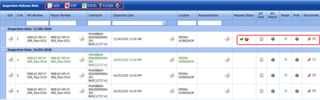
Figure 5.10: Inspection Release Note page

5.10.1 Add an Inspection Release Note
If you want to add an inspection release note, do the following steps,
- Click
 (ADD button) in the Inspection Release Note page.
The system redirects you into Inspection Release Note page. To know how to add an inspection release note, See the topic, “Add an Inspection Release Note”.

Once you have added the inspection release note, you must submit the added note to perform the release note inspection.
5.10.2 Add a Representative for Added Inspection Release Note
If you want to add a representative for any added inspection release note,
-
Click
 (Edit icon) in the Representative column for the respective inspection release note.
The Edit Form window opens.

- In the Inspection Date box, select the date of inspection.
- In the Representative box, enter the name of a representative.
- Click Save.


5.10.3 Edit an Inspection Release Note
If you want to edit any existing inspection release note in the Inspection Release Note page, do the following,
- Click
 (Edit icon) in the Edit column for the respective inspection release note. See Fig 5.10.
The Inspection Release Note page opens with the details of the selected inspection release note.
- Click any box where you want to edit the details, and then edit the details in the respective box.
- Click Save.

5.10.4 Submit an Inspection Release Note
Once you have added the inspection release note, the Request Status column in the Inspection Release Note page is appeared with (Submit and Reject icons). See Fig 5.10.
- If you want to submit the inspection release note, click
 (Submit icon) in the Request Status Otherwise click
  Reject icon) to reject the request.
The submitted request will be moved to for release note inspection.


5.10.5 Add RFI Data for an Inspection Release Note
If you want to add the details of RFI data for the added inspection release note, do the following steps,
-
Click (Edit icon) in the RFI Data column of the Inspection Release Note page. See Fig 5.10.
The RFI Inspection Request List window opens.

- In the Inspection From box, enter the detail from where the inspection should start.
- In the Inspection To box, enter the detail to where the inspection should end.
- In the Inspection Details option, select 1stInspection, 2nd Inspection or 3rd Inspection according to the inspection details.
- In the Others box, enter any other inspection related details.
- In the Refer to Report No box, enter the report number for reference.
- In the RFI Date box, choose the RFI date.
-
In the Inspection Result option, if the inspection result is accepted, select Accepted otherwise select Rejected.
- In the Remarks box, enter your remarks if any.
- In the Inspected by box, enter the name of a person who has done inspection.
- In the Inspected Date box, choose the date of inspection.
- In the Witnessed By box, enter the name of the witnessed person.
- In the Witnessed Date box, choose the date of witnessed.
- In the PCML Rep Name box, enter the representative name of PCML.
-
In the PCML Rep Date box, choose the PCML rep date.
- In the MEB Rep Name box, enter the representative name of MEB.
- In the MEB Rep Date box, choose MEB rep date.
- Click Save.

The RFI data for the inspection release note is added successfully.
5.10.6 Add Results of Inspection Release Note
After completing the inspection for the added release note, you can add the inspection result details. To add results, do the following steps,
- Click
 (Add icon) in the Results column of the respective request.
The INR List window opens with a list of spools added for the particular request.
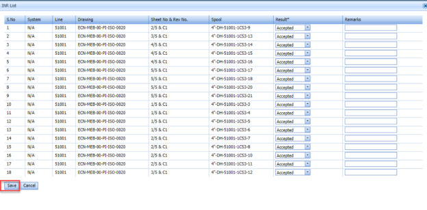
- In the Result column, select the result for each spool from the given result options in the drop-down list.
- In the Remarks box, enter your remarks if any.
- Click Save.


5.10.7 View an RFI Report
If you want to view an RFI report, click (print icon) provided in the RFI Report column of the Inspection Release Note page. See Fig 5.10.
5.10.8 View an Inspection Release Note Report
If you want to view an inspection release note report, click (print icon) provided in the Print column of the Inspection Release Note page. See Fig 5.10.
5.10.9 Attach a File into an Inspection Release Note
If you want to attach a file with any existing inspection release note listed in the Inspection Release Note page, you can attach the file by using  (Attach icon) in the Attachment column. To know how to attach, follow the procedures given in the topic “Attach a file into P&ID”.
5.10.10 View a Pipe Spool Release Summary
If you want to view a pipe spool release summary report, click (print icon) provided in the upper side of the Inspection Release Note page. See Fig 5.10.
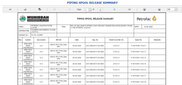
5.10.11 Export Inspection Release Note List
You can export a list of inspection release notes added in the Inspection Release Note page in both the pdf and excel formats by using  (PDF button) and
  (Excel button). To know how to export, see the topic, “Export P&ID list”.
5.10.12 Filter an Inspection Release Note
If you want to filter any specific inspection release note in the Inspection Release Note page, you can use  (FILTER button) located on the Inspection Release Note page. To know how to filter, see the topic, “Filter P&ID”.
5.11 Dimensional Inspection Request
The Dimensional Inspection Request tab in the Inspection menu helps you to add a dimensional inspection request. To navigate to the dimensional inspection request adding page,
-
Click Dimensional Inspection Request in the Inspection menu.
The Dimensional Inspection Request page opens.

Figure 5.11: Dimensional Inspection Request page
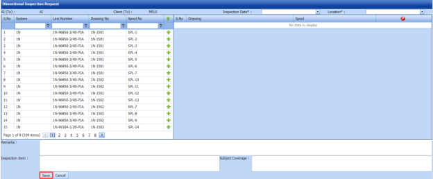
5.11.1 Add a Dimensional Inspection Request
If you want to add a new dimensional inspection request, do the following steps.
-
In the Inspection Date box, select the date of dimensional inspection.
- In the Location box, select the location where the dimensional inspection to be performed.
Before saving the added dimensional inspection request, you must add spools. You can add multiple spools for one dimensional inspection request.
 Note: The page shows a list of added spools. If you want to view the specific spools, use the filter options provided in the System, Line Number, Drawing Number, and Spool Number columns.
 - Click
 (Add icon) of the respective spool which you want to add.
The added spools will be moved to the right side of the page.
- In the Remarks box, enter your remarks if any.
- In the Inspection Item box, enter the details of inspection items.
-
Click Save.


The dimensional inspection request will be added and listed in the Dimensional Inspection List page.
5.12 Dimensional Inspection List
The Dimensional Inspection List tab helps you to view and edit the dimensional inspection request, which is added by using the Dimensional Inspection Request tab. This tab also allows you to add a new dimensional inspection request.
- Click Dimensional Inspection List in the Inspection menu.
The Dimensional Inspection List page opens with a list of added dimensional inspection requests.
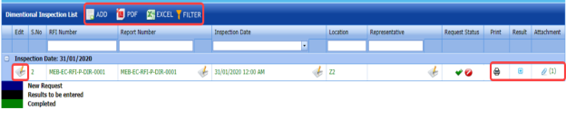
Figure 5.12: Dimensional Inspection List page

5.12.1 Add a Dimensional Inspection Request
If you want to add a dimensional inspection request, do the following steps,
-
Click
 (ADD button) in the Dimensional Inspection List page.
The system redirects you into the Dimensional Inspection Request page. To know how to add a dimensional inspection request, See the topic, “Add a Dimensional Inspection Request”.

Once you have added the dimensional inspection request, you must submit the added request to perform the dimensional inspection.
5.12.2 Add Representative for Added Dimensional Inspection Request
If you want to add a representative for any added dimensional inspection request,
- Click
 (Edit icon) in the Representative column for the respective spool release request.
The Edit Form window opens.
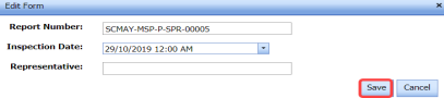
- In the Inspection Date box, select the date of inspection.
- In the Representative box, enter the name of a representative.
- Click Save.


5.12.3 Edit a Dimensional Inspection Request
If you want to edit any existing dimensional inspection request in the Dimensional Inspection List page, do the following,
- Click
 (Edit icon) in the Edit column for the respective dimensional inspection request. See Fig 5.12.
The page opens with the details of the selected dimensional inspection request.
- Click any box where you want to edit the details, and then edit the details in the respective box.
- Click Save.

5.12.4 Submit a Dimensional Inspection Request
Once you have added the dimensional inspection request, the Request Status column in the Dimensional Inspection List page is appeared with (Submit and Reject icons). See Fig 5.12.
- If you want to submit the dimensional inspection request, click
 (Submit icon) in the Request Status Otherwise click
  (Reject icon) to reject the request.


The submitted request will be moved to for the dimensional inspection.
5.12.5 Add Results of Dimensional Inspection
After completing the dimensional inspection for the added request, you can add the inspection result details. To add results, do the following steps,
-
Click
 (Add icon) in the Results column of the respective request.
The Dimensional Inspection List window opens with a list of added spools.

- In the Result column, select the result for each spool from the given result options.
- In the Pipe Size column, select the result of pipe size.
- In the Dimension column, select the result of pipe dimension.
- In the Flange column, select the result of flange.
- In the Orientation column, select the result of orientation.
- In the Remarks box, enter your remarks if any.
- Click Save.

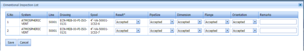
5.12.6 View a Dimensional Inspection Report
If you want to view a dimensional inspection report, click (print icon) provided in the Print column of the Dimensional Inspection List page. See Fig 5.12.
5.12.7 Attach a File into a Dimensional Inspection Request
If you want to attach a file with an existing dimensional inspection request listed in the Dimensional Inspection List page, you can attach the file by using  (Attach icon) in the Attachment column. To know how to attach, follow the procedures given in the topic “Attach a file into P&ID”
5.12.8 Export Dimensional Inspection Request List
You can export a list of dimensional inspection requests added in the Dimensional Inspection List page in both the pdf and excel formats by using  (PDF button) and
  (Excel button). To know how to export, see the topic, “Export P&ID list”.
5.12.9 Filter a Dimensional Inspection Request
If you want to filter any dimensional inspection request in the Dimensional Inspection List page, you can use  (FILTER button) located on the Dimensional Inspection List page. To know how to filter, see the topic, “Filter P&ID”.
5.13 RFI Hydro Pressure
Hydro Pressure Inspection is the technique in which pipes are tested at required design pressure of the pipes to check the leak and strength. You can add a request for hydro pressure inspection by using the RFI Hydro Pressure tab in the Inspection menu.
5.13.1 Add an RFI Hydro Pressure Request
If you want to add an RFI hydro pressure request, do the following steps,
-
Click RFI Hydro Pressure in the Inspection menu.
The RFI Hydro Pressure page opens.

Figure 5.13: RFI Hydro Pressure page
- In the Inspection Date & Time box, select the inspection date and time.
- In the Sub Contractor box, select a sub-contractor from a drop-down list.
- In the Acceptance Code box, enter the acceptance code detail.
- In the Designation box, enter the designation detail.
- In the Test Temperature box, enter the test temperature value.
- In the Test Medium box, select the test medium from the drop-down list.
- In the Requested By box, enter the name of a person who has requested the hydro pressure inspection.
- In the Classification box, enter the classification detail.
-
In the Drawing No box, select the drawing number from a drop-down list.
- In the Work Scope box, enter the work scope detail.
- In the Cost Centre box, enter the cost centre detail.
- In the Holding Time box, enter the holding time range.
- In the Pressure Gauge No box, enter the pressure gauge number.
- In the Location box, select the location where the inspection to be performed.
- In the System box, select a system from a drop-down list.
- In the Procedure No box, enter the procedure number.
- In the Design Pressure box, enter the design pressure range.
- In the Test Pressure box, enter the test pressure range.
- In the Instrument box, enter the instrument name.
- In the P&ID No box, enter the P&ID number.
- In the Remarks box, enter your remarks if any.
- In the Description box, enter the description for the hydro pressure inspection.
Before saving the added NDT request, you must add spools.
 Note: You can add multiple spools for one request.
The RFI Hydro Pressure page shows a list of added spools. If you want to view the spools for the specific ISO drawing, select the respective ISO drawing from a drop-down list.

- Click
 (Add icon) of the respective spool which you want to add.
The added spools will be moved to the right side of the page.

- Click Save Request.
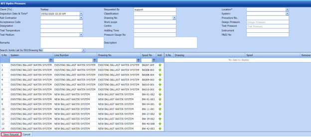


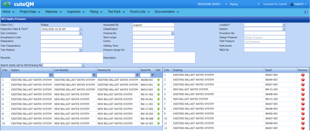
The hydro pressure inspection request will be added and listed in the RFI Hydro Pressure page.
5.14 View RFI Hydro Pressure
The View RFI Hydro Pressure tab helps you to view and edit the hydro pressure inspection request, which is added by using the RFI Hydro Pressure tab. This tab also allows you to add a new hydro pressure request.
-
Click View RFI Hydro Pressure in the Inspection menu.
The RFI Hydro Pressure page opens with a list of added hydro pressure requests.
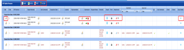
Figure 5.14: RFI Hydro Pressure page

5.14.1 Add a Hydro Pressure Inspection Request
If you want to add a hydro pressure inspection request, do the following steps,
-
Click
 (ADD button) in the RFI Hydro Pressure page.
The system redirects you to a new page to add a new hydro pressure inspection request. To know how to add a hydro pressure inspection request, See the topic, “Add a Hydro Pressure Inspection Request”.

Once you have added the hydro pressure inspection request, you must submit the added request to perform hydro pressure inspection.
5.14.2 Add Representative for Hydro Pressure Inspection Request
If you want to add a representative for any added hydro pressure inspection request,
-
Click
 (Edit icon) in the Representative column for the respective hydro pressure inspection request.
The Edit Form window opens.
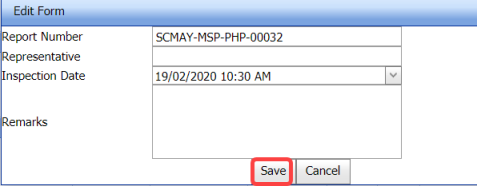
- In the Representative box, enter the name of a representative.
- In the Inspection Date box, select the date of inspection.
-
In the Remarks box, enter your remarks if any.
-
Click Save.


5.14.3 Edit a Hydro Pressure Inspection Request
If you want to edit any existing hydro pressure inspection request in the RFI Hydro Pressure page, do the following,
- Click
 (Edit icon) in the Edit column for the respective hydro pressure inspection See Fig 5.14.
The RFI Hydro Pressure page opens with the details of the selected hydro pressure inspection request.

-
Click any box where you want to edit the details, and then edit the details in the respective box.
- Click Save.

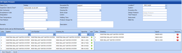
5.14.4 Submit and Approve a Hydro Pressure Inspection Request
Once you have added the hydro pressure inspection request, the Submission column in the RFI Hydro Pressure page is appeared with  (Submit and Reject icons).
- If you want to submit the hydro pressure inspection request, click
 (Submit icon) in the Submission Otherwise click
  (Reject icon) to reject the request.
Once you have submitted the hydro pressure inspection request, the Request Status column in the RFI Hydro Pressure page is appeared with
 (Approve and Reject icons).
 - If you want to approve the hydro pressure inspection request, click
 (Approve icon) in the Request Status Otherwise click
  (Reject icon) to reject the request.
The hydro pressure inspection request will be moved for hydro pressure inspection.


5.14.5 Add Results of Hydro Pressure Inspection
After completing the hydro pressure inspection for the added request, you can add the inspection result details. To add results, do the following steps,
-
Click
 (Add icon) in the Results column of the respective request.
The Result window opens a list of spools added for the particular request.
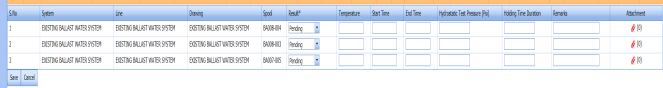
- In the Result column, select the result of each spool from the given result options in the drop-down list.
- In the Temperature column, enter the temperature value of each spool.
- In the Start Time and End Time columns, enter the start and end times.
- In the Hydrostatic Test Pressure column, enter the hydrostatic test pressure value.
- In the Holding Time Duration column, enter the holding time duration.
- In the Remarks column, enter your remarks if any.
- In the Attachment column, you want to attach any document.
-
Click Save.


5.14.6 View a Hydro Pressure Inspection Report
If you want to view a hydro pressure inspection report, click  (print icon) provided in the Print column of the RFI Hydro Pressure page. See Fig 5.14.
5.14.7 Attach a File into a hydro pressure inspection Request
If you want o attach a file with any existing hydro pressure inspection request listed in the RFI Hydro Pressure page, you can attach the file by using  (Attach icon) in the Attachment column. To know how to attach, follow the procedures given in the topic “Attach a file into P&ID”.
5.14.8 View Signature Details of Inspectors
You can view the sign details of the inspectors such as QA, Sub contractor, Client, and Owner, once they completed the hydro pressure inspection and submitted the inspection result details including their signature. To view the signature details, click  (Sign icon) in the Sign Details column in the RFI Hydro Pressure page.
5.14.9 Export Hydro Pressure Inspection Request List
You can export a list of hydro pressure requests added in the RFI Hydro Pressure page in both the pdf and excel formats by using  (PDF button) and
  (Excel button). To know how to export, see the topic, “Export P&ID list”.
5.14.10 Filter a Hydro Pressure Inspection Request
If you want to filter any specific hydro pressure inspection request in the RFI Hydro Pressure page, you can use  (FILTER button) located on the RFI Hydro Pressure page. To know how to filter, see the topic, “Filter P&ID”.
5.15 RFI Painting and Blasting
The RFI Painting and Blasting tab in the Inspection menu helps you to add an inspection request for painting and blasting in the piping project. To navigate to the painting and blasting inspection request adding page,
-
Click RFI Painting and Blasting in the Inspection menu.
The Blasting and Painting Inspection Record page opens.

Figure 5.15: Painting and blasting Inspection Request page
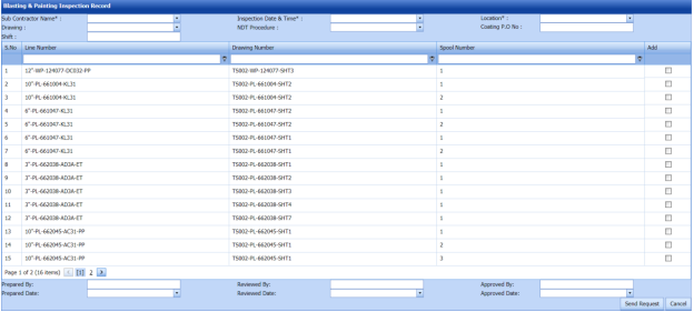
5.15.1 Add a Painting and Blasting Inspection Request
If you want to add a new painting and blasting inspection request, do the following steps.
- In the Sub Contractor Name box, select a sub-contractor from a drop-down list.
-
In the Inspection Date and Time box, select the date and time of painting and blasting inspection.
-
In the Location box, select the location where the painting and blasting inspection to be performed.
- In the Drawing box, select a drawing from a drop-down list.
- In the NDT Procedure box, select an NDT procedure from a drop-down list.
- In the Coating P.O No box, enter the purchase order number of coating.
- In the Shift box, enter the shit detail.
Before saving the added painting and blasting request, you must add spools. You can add multiple spools for one painting and blasting request.
 Note: The page shows a list of added spools. If you want to view the specific spools, use the filter options provided in the Line Number, Drawing Number, and Spool Number columns.
 - Select the checkbox of the respective spool which you want to add.
-
In the Prepared By box, enter the name of a person who has prepared the painting and blasting request.
- In the Prepared Date box, select the prepared date of the painting and blasting request.
- In the Reviewed By box, enter the name of a person who has reviewed the painting and blasting request.
- In the Reviewed Date box, select the reviewed date of the painting and blasting request.
- In the Approved By box, enter the name of a person who has approved the painting and blasting request.
- In the Approved Date box, select the approved date of the painting and blasting request.
- In the Remarks box, enter your remarks if any.
- Click Send Request.

The painting and blasting inspection request will be added and listed in the Blasting and Painting Inspection List page.
5.16 View Painting and Blasting
The View Painting and Blasting tab helps you to view and edit the painting and blasting inspection request, which is added by using the RFI Painting and Blasting tab. This tab also allows you to add a new painting and blasting inspection request.
-
Click View Painting and Blasting in the Inspection menu.
The Blasting and Painting Inspection List page opens with a list of added painting and blasting requests.

Figure 5.16: Blasting and Painting Inspection List page
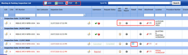
5.16.1 Add a Painting and Blasting Inspection Request
If you want to add a painting and blasting inspection request, do the following steps,
Once you have added the painting and blasting inspection request, you must submit the added request to perform the painting and blasting inspection.
5.16.2 Edit a Painting and Blasting Inspection Request
If you want to edit any existing painting and blasting inspection request in the Blasting and Painting Inspection List page, do the following steps,
-
Click
 (Edit icon) in the Edit column for the respective painting and blasting inspection request. See Fig 5.16.
The RFI Painting and Blasting page opens with the details of the selected painting and blasting inspection request.
- Click any box where you want to edit the details, and then edit the details in the respective box.
- Click Save.

5.16.3 Submit and Approve a Painting and Blasting Inspection Request
Once you have added the painting and blasting inspection request, the Submission column in the Blasting and Painting Inspection List page is appeared with  (Submit and Reject icons).
- If you want to submit the painting and blasting inspection request, click
 (Submit icon) in the Submission Otherwise click
  (Reject icon) to reject the request.
Once you have submitted the painting and blasting inspection request, the Request Status column in the Blasting and Painting Inspection List page is appeared with
 (Approve and Reject icons).
 -
If you want to approve the painting and blasting inspection request, click
 (Approve icon) in the Request Status column. Otherwise click
  (Reject icon) to reject the request.
The painting and blasting inspection request will be moved for painting and blasting inspection.


5.16.4 Add RFI Data for Piping and Blasting Inspection
If you want to add the details of RFI data for the added piping and blasting inspection request, do the following steps,
- Click
 (Edit icon) in the RFI Data column of the Blasting and Painting Inspection List See Fig 5.16.
The RFI Inspection Request List window opens.

- In the Inspection From box, enter the detail from where the inspection should start.
- In the Inspection To box, enter the detail to where the inspection should end.
- In the Inspection Details option, select 1stInspection, 2nd Inspection or 3rd Inspection according to the inspection details.
- In the Others box, enter any other inspection related details.
- In the Refer to Report No box, enter the report number for reference.
- In the RFI Date box, choose the RFI date.
- In the Inspection Result option, if the inspection result is accepted, select Accepted otherwise select Rejected.
- In the Remarks box, enter your remarks if any.
- In the Inspected by box, enter the name of a person who has done inspection.
- In the Inspected Date box, choose the date of inspection.
- In the Witnessed By box, enter the name of the witnessed person.
- In the Witnessed Date box, choose the date of witnessed.
- In the PCML Rep Name box, enter the representative name of PCML.
- In the PCML Rep Date box, choose the PCML rep date.
- In the MEB Rep Name box, enter the representative name of MEB.
- In the MEB Rep Date box, choose MEB rep date.
- Click Save.


The RFI data for the painting and blasting inspection is added successfully.
5.16.5 View a Painting and Blasting Inspection Report
If you want to view a painting and blasting inspection report, click  (print icon) provided in the Print column of the Blasting and Painting Inspection List page. See Fig 5.16.
5.16.6 Attach a File into a Painting and Blasting Inspection Request
If you want to attach a file with any existing painting and blasting inspection request listed in the Blasting and Painting Inspection List page, you can attach the file by using  (Attach icon) in the Attachment column. To know how to attach, follow the procedures given in the topic “Attach a file into P&ID”.
5.16.7 Export Painting and Blasting Inspection Request List
You can export a list of painting and blasting requests added in the Blasting and Painting Inspection List page in both the pdf and excel formats by using  (PDF button) and
  (Excel button). To know how to export, see the topic, “Export P&ID list”.
5.16.8 Filter a Painting and Blasting Inspection Request
If you want to filter any specific painting and blasting inspection request in the Blasting and Painting Inspection List page, you can filter the request based on the Spool No filter box.

5.16.9 View a Painting and Blasting Summary Report
If you want to view a painting and blasting summary report,
- Click
 (print icon) provided in the upper side of the Blasting and Painting Inspection List page.
The Blasting & Painting Summary Report page opens.
- In the ISO Drawing No box, select the ISO drawing number.
- In the Spool No box, select the spool number.
- Click Go.
The paining and blasting summary report detail opens.


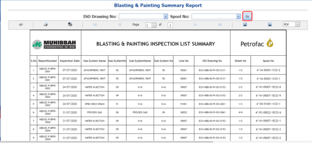
5.17 Other Application for Inspection (AFI) Requests or RFI Request – PWHT/PMI/Hardness/Ferrite
The Other AFI Requests tab in the Inspection menu helps you to add other AFI requests such as PWHT, PMI, Hardness and Ferrite requests.
- Click Other AFI Requests in the Inspection menu.
The RFI Request for PWHT/PMI/Hardness/Ferrite page opens.
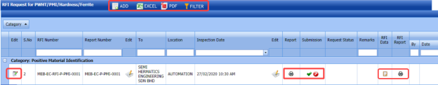
Figure 5.17: RFI Request for PWHT/PMI/Hardness/Ferrite page

5.17 Add an AFI Request
If you want to add an AFI request, do the following steps,
- Click (ADD button) in the RFI Request for PWHT/PMI/Hardness/Ferrite page.
The page opens a new window to add the details of the AFI request.

- In the Requested By box, enter the name of a person who has requested the AFI inspection.
- In the To box, select the sub-contractor for the AFI inspection.
-
In the Location box, select a location from a drop-down list.
- In the Inspection Date and Time box, select the inspection date and time.
- In the Requisition box, enter the requisition detail of the AFI inspection.
- In the Drawing No box, select the drawing number from a drop-down list.
- In the Designation box, enter the designation detail.
- In the Cost Centre box, enter the cost centre detail.
- In System box, select a system from a drop-down list.
- In the Type box, select the type of AFI for which you want to add request.
- In the Test Description box, enter the test description detail.
Before saving the added request, you must add joints. You can add multiple joints for one request.
 Note: The page shows a list of added joints. If you want to view the joints for the specific isometric drawing, use the filter option.
- Click
 (Add icon) of the respective joint which you want to add.
The added joints will be moved to the right side of the page.

- Click Save.
The AFI inspection request will be added and listed in the RFI Request for PWHT/PMI/ Hardness /Ferrite page. Once you have added the AFI inspection request, you must submit the added request to perform the respective inspection.
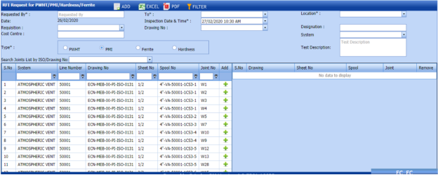


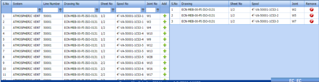
5.17.2 Edit an AFI Inspection Request
If you want to edit any existing AFI inspection request in the RFI Request for PWHT/PMI/ Hardness /Ferrite page, do the following steps,
-
Click
 (Edit icon) in the Edit column for the respective AFI request. See Fig 5.17.
The page shows the details of the selected AFI request.
- Click any box where you want to edit the details, and then edit the details in the respective box.
- Click Save.

5.17.3 Submit and Approve an AFI Inspection Request
Once you have added the AFI inspection request, the Submission column in the RFI Request for PWHT/PMI/ Hardness /Ferrite page is appeared with  (Submit and Reject icons).
- If you want to submit the AFI inspection request, click
 (Submit icon) in the Submission Otherwise click
  (Reject icon) to reject the request.
Once you have submitted the AFI inspection request, the Request Status column in the RFI Request for PWHT/PMI/ Hardness /Ferrite page is appeared with (Approve and Reject icons).
- If you want to approve the AFI inspection request, click
 (Approve icon) in the Request Status Otherwise click
  (Reject icon) to reject the request.
The AFI inspection request will be moved for inspection.


5.17.4 Add RFI Data for an AFI Inspection Request
If you want to add the details of RFI data for the added AFI inspection request, do the following steps,
- Click (Edit icon) in the RFI Data column of the RFI Request for PWHT/PMI/ Hardness /Ferrite page. See Fig 5.17.
The RFI Inspection Request List window opens.

- In the Inspection From box, enter the detail from where the inspection should start.
-
In the Inspection To box, enter the detail to where the inspection should end.
-
In the Inspection Details option, select 1st Inspection, 2nd Inspection or 3rd Inspection according to the inspection details.
- In the Others box, enter any other inspection related details.
- In the Refer to Report No box, enter the report number for reference.
- In the RFI Date box, choose the RFI date.
- In the Inspection Result option, if the inspection result is accepted, select Accepted otherwise select Rejected.
- In the Remarks box, enter your remarks if any.
- In the Inspected by box, enter the name of a person who has done inspection.
- In the Inspected Date box, choose the date of inspection.
- In the Witnessed By box, enter the name of the witnessed person.
- In the Witnessed Date box, choose the date of witnessed.
- In the PCML Rep Name box, enter the representative name of PCML.
- In the PCML Rep Date box, choose the PCML rep date.
- In the MEB Rep Date box, choose MEB rep date.
- Click Save.
The RFI data for the AFI inspection is added successfully.

5.17.5 View an AFI Inspection Report
If you want to view an AFI inspection report, click (print icon) provided in the Print column of the RFI Request for PWHT/PMI/ Hardness /Ferrite page. See Fig 5.17.
5.17.6 Export AFI Inspection Request List
You can export a list of AFI requests added in the RFI Request for PWHT/PMI/ Hardness /Ferrite page in both the pdf and excel formats by using (PDF button) and (Excel button). To know how to export, see the topic, “Export P&ID list”.
5.17.7 Filter an AFI Inspection Request
If you want to filter any specific AFI inspection request in the RFI Request for PWHT/PMI/ Hardness /Ferrite page, you can use  (FILTER button) located on the RFI Request for PWHT/PMI/ Hardness /Ferrite page. To know how to filter, see the topic, “Filter P&ID”.
5.18 Painting & Coasting FIR
The Painting Coasting FIR tab in the Inspection menu helps you to add a painting & coasting FIR.
- Click Painting Coasting FIR in the Inspection menu.
The Painting & Coasting FIR page opens.
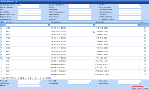
Figure 5.18: Painting & Coasting FIR page
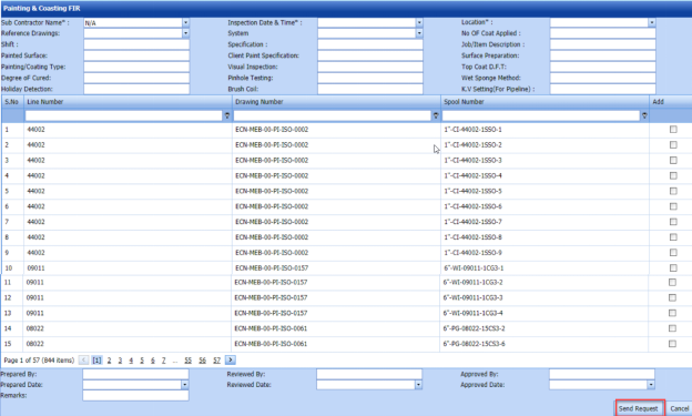
5.18.1 Add a Painting and Coasting FIR
If you want to add a new painting and coasting FIR, do the following steps.
-
In the Sub Contractor Name box, select a sub-contractor from a drop-down list.
-
In the Inspection Date and Time box, select the date and time of painting and blasting inspection.
- In the Location box, select the location where the painting and coasting inspection to be performed.
- In the Reference Drawing box, select a reference drawing from a drop-down list.
- In the System box, select a system from a drop-down list.
- In the No of Coat Applied box, enter the number of applied coating.
- In the Shift box, enter the shift detail.
- In the Specification box, enter the specification detail.
- In the Job/Item Description box, enter the description for the job/item.
- In the Painted Surface box, enter the painted surface detail.
- In the Client Paint Specification box, enter the client paint specification detail.
- In the Surface Preparation box, enter the surface preparation detail.
- In the Painting/Coating Type box, enter the painting/coating type.
- In the Visual Inspection box, enter the visual inspection detail.
- In the Top Coat D.F.T box, enter the top coat detail.
- In the Degree of Cured box, enter the degree of cured.
- In the Pinhole Testing box, enter the pinhole testing detail.
- In the Wet Sponge Method box, enter the wet sponge method detail.
- In the Holiday Detection box, enter the holiday detection detail.
- In the Brush Coil box, enter the brush coil detail.
- In the V Setting (For Pipeline)box, enter the K.V setting detail for pipeline.
Before saving the added painting and coasting request, you must add spools. You can add multiple spools for one painting and coasting request.
 Note: The page shows a list of added spools. If you want to view the specific spools, use the filter options provided in the Line Number, Drawing Number, and Spool Number columns.
 -
Select the checkbox of the respective spool which you want to add.
-
In the Prepared By box, enter the name of a person who has prepared the painting and coasting request.
- In the Prepared Date box, select the prepared date of the painting and coasting request.
- In the Reviewed By box, enter the name of a person who has reviewed the painting and coasting request.
- In the Reviewed Date box, select the reviewed date of the painting and coasting request.
- In the Approved By box, enter the name of a person who has approved the painting and coasting request.
-
In the Approved Date box, select the approved date of the painting and coasting request.
- In the Remarks box, enter your remarks if any.
- Click Send Request.

The painting and coasting inspection request will be added and listed in the Panting and Coasting FIR page.
5.19 View Painting & Coasting FIR
The View Painting and Coasting tab helps you to view and edit the painting and coasting FIR, which is added by using the Painting & Blasting FIR tab. This tab also allows you to add a new painting and coasting inspection request.
-
Click View Painting and Coasting in the Inspection menu.
The Painting Coasting FIR page opens with a list of added painting and coasting FIRs.
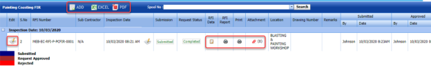
Figure 5.19: Painting Coasting FIR page

5.19.1 Add a Painting and Coasting FIR
If you want to add a painting and coasting FIR, do the following steps,
- Click
 (ADD button) in the Painting Coasting FIR page.
The system redirects you to the Painting & Coasting FIR page to add a new painting and coasting request. To know how to add a painting and coasting inspection request, See the topic, “Add a Painting and Coasting FIR”.

Once you have added the painting and coasting inspection request, you must submit the added request to perform the painting and coasting inspection.
5.19.2 Edit a Painting and Coasting FIR
If you want to edit any existing painting and coasting inspection request in the Painting Coasting FIR page, do the following steps,
-
Click
 (Edit icon) in the Edit column for the respective painting and coasting inspection request. See Fig 5.19.
The Painting and Coasting FIR page opens with the details of the selected painting and coasting inspection request.
- Click any box where you want to edit the details, and then edit the details in the respective box.
-
Click Save.

5.19.3 Submit and Approve a Painting and coasting FIR
Once you have added the painting and coasting inspection request, the Submission column in the Painting Coasting FIR page is appeared with  (Submit and Reject icons).
-
If you want to submit the painting and coasting inspection request, click
 (Submit icon) in the Submission column. Otherwise click
  (Reject icon) to reject the request.
Once you have submitted the painting and coasting inspection request, the Request Status column in the Painting Coasting FIR page is appeared with
 (Approve and Reject icons).
 -
If you want to approve the painting and coasting inspection request, click
 (Approve icon) in the Request Status column. Otherwise click
  (Reject icon) to reject the request.
The painting and coasting inspection request will be moved for painting and coasting inspection.


5.19.4 Add RFI Data for Painting and Coasting Inspection
If you want to add the details of RFI data for the added painting and coasting inspection request, do the following steps,
- Click
 (Edit icon) in the RFI Data column of the Painting Coasting FIR See Fig 5.19.
The RFI Inspection Request List window opens.

-
In the Inspection From box, enter the detail from where the inspection should start.
- In the Inspection To box, enter the detail to where the inspection should end.
- In the Inspection Details option, select 1stInspection, 2nd Inspection or 3rd Inspection according to the inspection details.
- In the Others box, enter any other inspection related details.
- In the Refer to Report No box, enter the report number for reference.
- In the RFI Date box, choose the RFI date.
- In the Inspection Result option, if the inspection result is accepted, select Accepted otherwise select Rejected.
- In the Remarks box, enter your remarks if any.
- In the Inspected by box, enter the name of a person who has done inspection.
- In the Inspected Date box, choose the date of inspection.
- In the Witnessed By box, enter the name of the witnessed person.
- In the Witnessed Date box, choose the date of witnessed.
- In the PCML Rep Name box, enter the representative name of PCML.
- In the PCML Rep Date box, choose the PCML rep date.
- In the MEB Rep Name box, enter the representative name of MEB.
- In the MEB Rep Date box, choose MEB rep date.
- Click Save.
The RFI data for the painting and coasting inspection is added successfully.


5.19.5 View an RFI Report
If you want to view an RFI report, click  (print icon) provided in the RFI Report column of the Painting Coasting FIR page. See Fig 5.19.
5.19.6 View a Painting and Coasting FIR Report
If you want to view a painting and coasting FIR report, click  (print icon) provided in the Print column of the Painting Coasting FIR page. See Fig 5.19.
5.19.7 Attach a File into a Painting and Coasting FIR
If you want to attach a file with any existing painting and coasting inspection request listed in the Painting Coasting FIR page, you can attach the file by using (Attach icon) in the Attachment column. To know how to attach, follow the procedures given in the topic “Attach a file into P&ID”.
5.19.8 Export Painting and Coasting FIR List
You can export a list of painting and coasting requests added in the Painting Coasting FIR page in both the pdf and excel formats by using  (PDF button) and
  (Excel button). To know how to export, see the topic, “Export P&ID list”.
5.19.9 Filter a Painting and Coasting FIR
If you want to filter any specific painting and coasting inspection request in the Painting Coasting FIR page, you can filter the request based on the Spool No filter box. 
5.20 Final Inspection Report
The Final Inspection Report tab in the Inspection menu helps you to add a final inspection report. To navigate to the final inspection report adding page,
-
Click Final Inspection Report in the Inspection menu.
The Final Inspection Report page opens with a Weld Map Drawing Detail window.

Figure 5.20: Final Inspection Report page
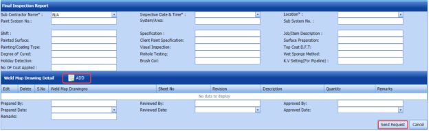
5.20.1 Add a Final Inspection Report
If you want to add a new final inspection report, do the following steps,
-
In the Sub Contractor Name box, select a sub-contractor from a drop-down list.
- In the Inspection Date and Time box, select the date and time of final inspection.
- In the Location box, select the location where the final inspection to be performed.
- In the Paint System No box, enter the paint system number.
- In the System/Area box, enter the system/area name.
- In the Sub System No box, enter the sub system number.
- In the Shift box, enter the shift detail.
- In the Specification box, enter the specification detail.
- In the Job/Item Description box, enter the description for the job/item.
- In the Painted Surface box, enter the painted surface detail.
- In the Client Paint Specification box, enter the client paint specification detail.
- In the Surface Preparation box, enter the surface preparation detail.
- In the Painting/Coating Type box, enter the painting/coating type.
- In the Visual Inspection box, enter the visual inspection detail.
- In the Top Coat D.F.T box, enter the top coat detail.
- In the Degree of Cured box, enter the degree of cured.
- In the Pinhole Testing box, enter the pinhole testing detail.
- In the Wet Sponge Method box, enter the wet sponge method detail.
- In the Holiday Detection box, enter the holiday detection detail.
- In the Brush Coil box, enter the brush coil detail.
- In the V Setting (For Pipeline) box, enter the K.V setting detail for pipeline.
- In the No of Coat Applied box, enter the number of coats applied.
Before saving the added final inspection request, you must add weld map drawing detail.
-
Click
 (ADD button) in the Weld Map Drawing Detail window. See Figure 5.19.
The Edit Form window shows a new window to add the details of weld map drawing.

-
In the Weld Map Drawing No box, enter the weld map drawing number.
-
In the Sheet No box, enter the sheet number.
-
In the Revision box, enter the revision for the weld map drawing.
-
In the Description box, enter the description for the weld map drawing.
-
In the Quantity box, enter the quantity of the weld map drawing.
-
In the Remarks box, enter your remarks if any.
-
Click Update.
The weld map drawing is updated.
- In the Prepared By box, enter the name of a person who has prepared the final inspection request.
- In the Prepared Date box, select the prepared date of the final inspection request.
- In the Reviewed By box, enter the name of a person who has reviewed the final inspection request.
- In the Reviewed Date box, select the reviewed date of the final inspection request.
- In the Approved By box, enter the name of a person who has approved the final inspection request.
- In the Approved Date box, select the approved date of the final inspection request.
- In the Remarks box, enter your remarks if any.
- Click Send Request.
The final inspection request will be added and listed in the Final Inspection Report page.

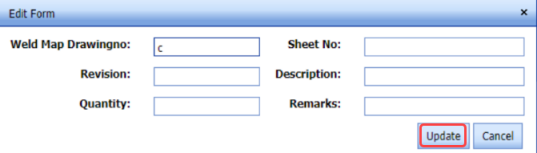
5.21 View Final Inspection Report
The View Final Inspection Report tab helps you to view and edit the final inspection request, which is added by using the Final Inspection Report tab. This tab also allows you to add a new final inspection request.
-
Click View Final Inspection Report in the Inspection menu.
The Final Inspection Report page opens with a list of added final inspection reports.
 Figure 5.21: View Final Inspection Report page
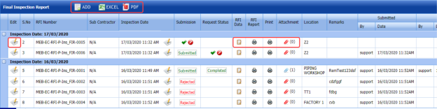
5.21.1 Add a Final Inspection Report
If you want to add a final inspection report, do the following steps,
-
Click
 (ADD button) in the View Final Inspection Report page.
The system redirects you to the Final Inspection Report page to add a new final inspection report. To know how to add a final inspection report, See the topic, “Add a Final Inspection Report”.

Once you have added the final inspection report, you must submit the added report to perform the final inspection.
5.21.2 Edit a Final Inspection Report
If you want to edit any existing final inspection report in the Final Inspection Report page, do the following steps,
-
Click
 (Edit icon) in the Edit column for the respective final inspection report. See Fig 5.21.
The Final Inspection Report page opens with the details of the selected final inspection report.
- Click any box where you want to edit the details, and then edit the details in the respective box.
-
Click Save.

5.21.3 Submit and Approve a Final Inspection Report
Once you have added the final inspection report, the Submission column in the Final Inspection Report page is appeared with  (Submit and Reject icons).
-
If you want to submit the final inspection report, click
 (Submit icon) in the Submission column. Otherwise click
  (Reject icon) to reject the request.
Once you have submitted the final inspection report, the Request Status column in the Final Inspection Report page is appeared with
 (Approve and Reject icons).
 - If you want to approve the final inspection report, click (Approve icon) in the Request Status Otherwise click (Reject icon) to reject the request.
The final inspection report will be moved for final inspection.


5.21.4 Add RFI Data for a Final Inspection Report
If you want to add the details of RFI data for the added final inspection report, do the following steps,
- Click
 (Edit icon) in the RFI Data column of the Final Inspection Report See Fig 5.21.
The RFI Inspection Request List window opens.

- In the Inspection From box, enter the detail from where the inspection should start.
-
In the Inspection To box, enter the detail to where the inspection should end.
-
In the Inspection To box, enter the detail to where the inspection should end.
-
In the Others box, enter any other inspection related details.
- In the Refer to Report No box, enter the report number for reference.
- In the RFI Date box, choose the RFI date.
- In the Inspection Result option, if the inspection result is accepted, select Accepted otherwise select Rejected.
- In the Remarks box, enter your remarks if any.
- In the Inspected by box, enter the name of a person who has done inspection.
-
In the Inspected Date box, choose the date of inspection.
- In the Witnessed By box, enter the name of the witnessed person.
- In the Witnessed Date box, choose the date of witnessed.
- In the PCML Rep Name box, enter the representative name of PCML.
- In the PCML Rep Date box, choose the PCML rep date.
- In the MEB Rep Name box, enter the representative name of MEB.
- In the MEB Rep Date box, choose MEB rep date.
- Click Save.
The RFI data for the final inspection report is added successfully.


5.21.5 View an RFI Report
If you want to view an RFI report, click  (print icon) provided in the RFI Report column of the Final Inspection Report page. See Fig 5.21.
5.21.6 View a Final Inspection Report
If you want to view a final inspection report, click  (print icon) provided in the Print column of the Final Inspection Report page. See Fig 5.21.
5.21.7 Attach a File into a Final Inspection Report
If you want to attach a file with any existing final inspection report listed in the Final Inspection Report page, you can attach the file by using  (Attach icon) in the Attachment column. To know how to attach, follow the procedures given in the topic “Attach a file into P&ID”.
5.21.8 Export Final Inspection Report List
You can export a list of final inspection reports added in the Final Inspection Report page in both the pdf and excel formats by using  (PDF button) and
  (Excel button). To know how to export, see the topic, “Export P&ID list”.
5.22 Generate Daily Pipe Welder Record (DPWR)
The Generate Daily Pipe Welder Record tab in the Inspection menu helps you to generate a DPWR.
- Click Generate Daily Pipe Welder Record in the Inspection menu.
The Daily Pipe Welder Record page opens.

Figure 5.22: Daily Pipe Welder Record page
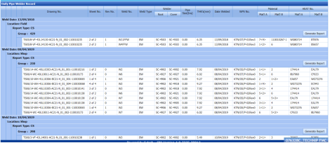
The Daily Pipe Welder Record page shows the list of welding completed on each day including the details of the welder, location, and report type.
- In this page, the welding completed details are grouped based on the respective date.
- Each group has a maximum of 20 number of welding.
- Each group is separated by different group number.
- You can generate a report for each group individually by using the respective report generating option provided in the Daily Pipe Welder Record page.
2. If you want to generate report of DPWR for any group or date, click  (Generate Report button) of the respective group or date.
The generated reports will be moved to the Daily Pipe Welder Record page. To view the generated reports, navigate to the Daily Pipe Welder Record tab.
5.23 Daily Pipe Welder Record (DWPR)
The Daily Pipe Welder Record tab in the Inspection menu helps you to view a DPWR report, which is generated using the Generate Daily Pipe Welder Record tab. To view the generated report,
- Click Daily Pipe Welder Record in the Inspection menu.
The Daily Pipe Welder Record page opens including the generated DPWR reports.
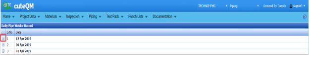
Figure 5.23: Daily Pipe Welder Record page
The generated DPWR reports are listed based on the welding date.
-
If you want to view the DPWR report for any particular date, click (Expand icon) of the respective date.
The Reports window opens including the report number and report type.
- Click
 (Print icon) in the Print column.
The Report will be opened.


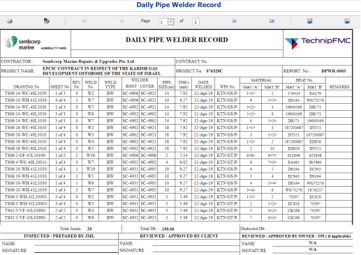
5.24 Individual Pipe Welder Record
The Individual Pipe Welder Record tab in the Inspection menu used to view the completed pipe welding details of each welder individually.
-
Click Individual Pipe Welder Record in the Inspection menu.
The Individual Pipe Welder Record page opens.
Figure 5.24: Individual Pipe Welder Record page
-
In the Welder box, select a welder from a drop-down list.
-
In the Joint Category box, select a joint category from the given option.
The completed welding details of selected welder will be displayed.

5.25 Weekly Welders Performance Record
If you want to view the performance record of welders on weekly basis, navigate to the Weekly Welders Performance Record tab in the Inspection menu.
- Click Weekly Welders Performance Record in the Inspection menu.
The Weekly Welders Performance Record page opens.

Figure 5.25: Weekly Welders Performance Record page
-
If you want to view the performance record of welders for all the projects, select the checkbox of the All Project option.
- In the NDT Type box, select the NDT type from a drop-down list.
- In the Joint Category box, select the joint category of pipe whether Shop, Field, or All from a drop-down list.
- In the From Date and To Date boxes, select the from and to dates.
- Click Show Report.
The performance record of welders will be opened.

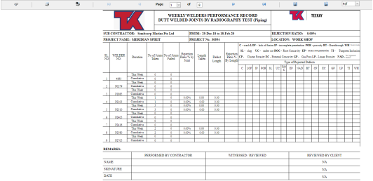
5.25.1 Print a Weekly Welders Performance Record
If you want to print a weekly welders performance record, use  and
and  (print icons) provided in the Weekly Welders Performance Record page.
- If you want to print the current page of the weekly welder performance record, click
 (print icon including the page number).
 - If you want to print all the pages of the weekly welder performance record, click
 (print icon).


5.25.2 Export a Weekly Welders Performance Record
You can export the weekly welders performance record in various formats by using the option  provided in the upper right corner of the Weekly Welders Performance Record page.
5.26 RFI and AFI Excel Import
The RFI and AFI Excel Import tab in the Inspection menu helps you to upload various data related with RFI and AFI for different fields included in the Project Data menu instead of uploading data for each field individually. If you want to import data for different fields, do the following,
- Click the RFI and AFI Excel Import tab in the Inspection menu.
The File Upload page opens.

- Download a template by clicking
 (TEMPLATE button) to enter the details of RFI and AFI data.
An excel worksheet will be downloaded as a pre-defined template.
- Enter the relevant details in the respective column of the excel worksheet based on the columns listed in the System Column field.
- Click
 (Choose File button).
Once the file has been uploaded successfully, you receive a message, “Successfully uploaded”
-
Click
 (Get Columns button).
The columns added in the excel worksheet will be listed in the Excel Column field.
- Click
 .
.
The system automatically maps the System Column field and the Excel Column field and displays in the Mapped Columns field.

- If you want to map any columns or to unmap any mapped columns, select the respective columns and then click
 (Map button) and
  (UnMap button) accordingly.
 Note: If you want to unmap all columns, click
  .
. -
Once you have completed the mapping and un mapping of columns, in the Upload Range From and To fields, enter the range of rows you want to upload from the excel worksheet.
 Note: In the Total Rows field, the system indicates the total number of rows filled in the excel worksheet.
 Tip: You must enter the upload starting range as two in the Upload Range From field because a first row in the excel worksheet is having heading of the columns.
 - Click
 (Populate Value button).
 -
Click
 (Process button).
Once you have clicked the Process button, the system processes the columns and displays in the Excel Import page.

- Click
 (Import button) to import the data added in the excel worksheet.
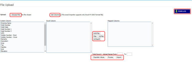


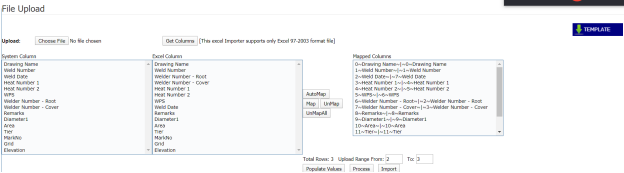


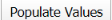

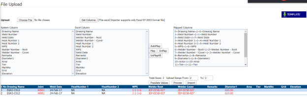

5.27 RFI and AFI Joint Status
The RFI and AFI Joint Status tab in the Inspection menu used to view the RFI and AFI fit up and weld inspection completed status for the joints.
- Click RFI and AFI Joint Status in the Inspection.
The RFI and AFI Joints Status page opens.
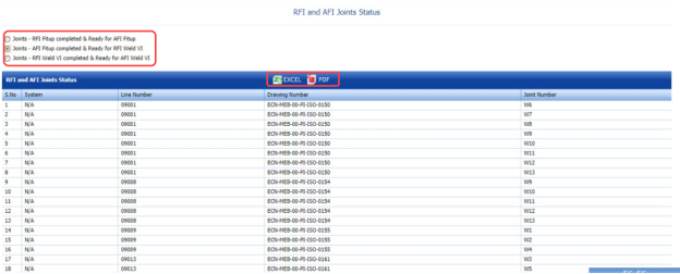
Figure 5.27: RFI and AFI Joints Status page

You can view the status of the joints by selecting one of the below options given in the page.
-
Joints – RFI Fit up completed & Ready for AFI Fit up
-
Joints – AFI Fit up completed & Ready for RFI Weld VI
- Joints – RFI Weld VI completed & Ready for AFI Weld VI
For example, if you select the Joints – AFI Fit up completed & Ready for RFI Weld VI option, then the system shows the list of joints which has completed the AFI fit up and are ready for RFI weld VI.
5.27.1 Export the RFI and AFI Joints Status
You can export the joint status including a list of joints in the RFI and AFI Joints Status page in both the pdf and excel formats by using  (PDF button) and
  (Excel button). To know how to export, see the topic, “Export P&ID list”.
5.28 RFI and AFI Status
The RFI and AFI Status tab in the Inspection menu used to view and check the status of the RFI and AFI inspection status.
- Click RFI and AFI Status in the Inspection menu.
The RFI and AFI Status page opens.

Figure 5.28: RFI and AFI Status page
The page shows the total number of added RFI and AFI inspection requests, and also shows the number of completed and outstanding inspections.
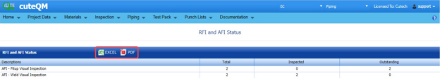
5.28.1 Export the RFI and AFI Status
You can export the RFI and AFI status in both the pdf and excel formats by using  (PDF button) and
  (Excel button). To know how to export, see the topic, “Export P&ID list”.
5.29 Threaded Joint Report
The Threaded Joint Report tab in the Inspection menu used to view and update the completed status of the threaded joints.
- Click Threaded Joint Report in the Inspection menu.
The Threaded Joints page opens.

Figure 5.29: Threaded Joints page
- In the Status column, select the status of the joints.
If you select Pending, the page shows the details of the joints which are pending.
- Click Search.
- In the Complete column, if the particular joint has completed then enable the checkbox of the respective joint.
- In the Completed by box, enter the name of a person who has completed the joint work.
- In the Completed Date box, select the completed date of the joint work.
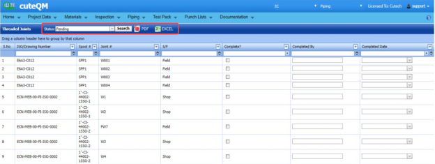
5.29.1 Export a Threaded Joint Report
You can export the threaded joint report in both the pdf and excel formats by using  (PDF button) and
  (Excel button). To know how to export, see the topic, “Export P&ID list”.
5.30 Welder Performance Report
The Welder Performance Report tab in the Inspection menu used to view the performance report of each welder for a particular project.
-
Click Welder Performance Report in the Inspection menu.
The Welder Performance Report page opens.
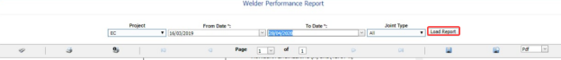
Figure 5.30: Welder Performance Report page
- In the Project box, select a project from a drop-down list.
- In the From Date and To Date boxes, select the from and to dates.
- In the Joint Type box, select the joint type.
- Click Load Report..
The performance report for the selected project will be opened.
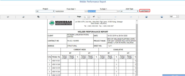


5.30.1 Print a Welder Performance Report
If you want to print a welder performance report, use  and
and  (print icons) provided in the Welder Performance Report page.
- If you want to print the current page of the welder performance report, click
 (print icon including the page number).
 - If you want to print all the pages of the welder performance report, click
 (print icon).


5.30.2 Export a Welder Performance Report
You can export the welder performance report in various formats by using the option  provided in the upper right corner of the Welder Performance Report page.
5.31 Create Auto Fit up and Visual Request
If you want to create the new fit up and visual requests in both RFI and AFI automatically, you can create by using the Create Auto Fit up and Visual Request tab in the Inspection menu.
- Click Create Auto Fit up and Visual Request in the Inspection menu.
The RFI and AFI Create page opens.
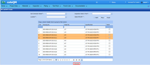
Figure 5.31: RFI and AFI Create page
- In the Sub Contractor Name box, select a sub-contractor.
- In the Inspection Date and Time box, select the inspection date and time.
- In the Location box, select the location.
- In the Select RFI/AFI box, if you want to create the fit up or visual request, select Fit up or Visual. If you want to create both fit up and visual, select Both.
The page shows the list of drawing numbers, sheet numbers, and spool numbers.
- Select the checkbox of the respective drawing, sheet and spool number which you want to add for creating the request.
- Click Generate.
The selected RFI and AFI request will be added and moved into the respective requests page.

5.32 Weld Rejection Statistics Record
If you want to view the statistics report of weld rejection rate, navigate to the Weld Rejection Statistics Record tab in the Inspection menu.
- Click Weld Rejection Statistics Record in the Inspection menu.
The Weld Rejection Statistics Report page opens.

Figure 5.32: Weld Rejection Statistics Report page
- In the Sub Contractor box, select a sub-contractor from a list.
- In the From Date and To Date boxes, select the from and to dates.
- Click Load Report.
The statistics report of the weld rejection rate will be displayed.
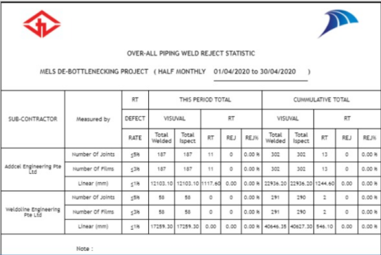
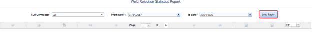

5.32.1 Print a Weld Rejection Statistics Record
If you want to print the weld rejection statistics details, use  and
and  (print icons) provided in the Weld Rejection Statistics Report page.
- If you want to print the current page of the weld rejection statistics record, click (print icon including the page number).
- If you want to print all the pages of the weld rejection statistics record, click
 (print icon).

5.32.2 Export a Weld Rejection Statistics Record
You can export the weld rejection statistics details in various formats by using the option  provided in the upper right corner of the Weld Rejection Statistics Report page.
5.33 View Spool Contractor
The View Spool Contractor tab in the Inspection menu used to view and add the details of the spool installation contractor.
-
Click View Spool Contractor in the Inspection menu.
The Spool Installation Contractor page opens.

Figure 5.33: Spool Installation Contractor page
-
In the Sheet No/ Drawing No/ Revision box, select the respective sheet, drawing and revision numbers.
The list of spools for the selected drawing number opens.
- Enter the contractor name for the respective spools in the Contractor Name
- Click Save Changes.
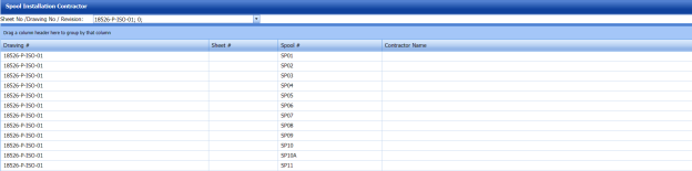
5.34 RFI Mechanical Completion Request
Mechanical completion takes place through all phases of the piping project, starting at equipment supplier and continuing through fabrication up to commissioning phase. Mechanical completion encompasses all disciplines. If you want to add an RFI mechanical completion request,
- Click RFI Mechanical Completion Request in the Inspection menu.
The RFI Mechanical Completion Request page opens.
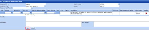
Figure 5.34: RFI Mechanical Completion Request page

5.34.1 Add an RFI Mechanical Completion Request
If you want to add an RFI mechanical completion request, do the following steps,
-
In the Sub Contractor box, select a sub-contractor from a drop-down list.
- In the Inspection Date box, select the date of inspection.
- In the Location box, enter the name of the location.
Before saving the added RFI mechanical completion request, you must add a system. You can add multiple system for one request.
 Note: The page shows a list of added systems. If you want to view the specific system, use the Search by Test Pack No filter box or use the filter options provided in the System, Sub System, Test Pack, and Check Records columns.
 - Select the checkbox of the respective system which you want to add.
- In the Remarks box, enter your remarks if any.
- In the Description box, enter the description for the request.
- In the Work Scope box, enter the work scope detail.
- Click Save.
The RFI mechanical completion request will be added and listed in the View RFI Mechanical Completion page.

5.35 View RFI Mechanical Completion
The View RFI Mechanical Completion tab helps you to view and edit the RFI mechanical completion request, which is added by using the RFI Mechanical Completion Request tab. This tab also allows you to add a new RFI mechanical completion request.
- Click View RFI Mechanical Completion in the Inspection menu.
The View RFI Mechanical Completion List page opens with a list of added RFI mechanical completion requests.

Figure 5.35: View RFI Mechanical Completion List page
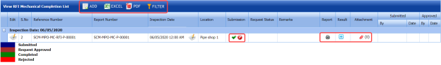
5.35.1 Add an RFI Mechanical Completion Request
If you want to add an RFI mechanical completion request, do the following steps,
Once you have added the RFI mechanical completion request, you must submit the added request to perform mechanical completion inspection.
5.35.2 Edit an RFI Mechanical Completion Request
If you want to edit any existing mechanical completion request in the View RFI Mechanical Completion List page, do the following,
- Click
 (Edit icon) in the Edit column for the respective RFI mechanical completion request. See Fig 8.35.
The RFI Mechanical Completion Request page opens with the details of the selected RFI mechanical completion request.
-
Click any box where you want to edit the details, and then edit the details in the respective box.
- Click Save.

5.35.3 Submit and Approve an RFI Mechanical Completion Request
Once you have added the RFI mechanical completion request, the Submission column in the RFI Mechanical Completion Request page is appeared with  (Submit and Reject icons).
- If you want to submit the mechanical completion request, click
 (Submit icon) in the Submission Otherwise click
 (Reject icon) to reject the request.
Once you have submitted the mechanical completion request, the Request Status column in the View RFI Mechanical Completion List page is appeared with
 (Approve and Reject icons).
 - If you want to approve the mechanical completion request, click
 (Approve icon) in the Request Status Otherwise click
  (Reject icon) to reject the request.


The mechanical completion request will be moved for mechanical completion inspection.
5.35.4 Add Results of Mechanical Completion Inspection
After completing the mechanical completion inspection for the added request, you can add the inspection result details. To add results, do the following steps,
-
Click
 (Add icon) in the Results column of the respective request.
The Result window opens a list of test pack added for the particular request.

- In the Result column, select the result of each test pack from the given result options in the drop-down list.
- In the Remarks column, enter your remarks if any.
- Click Approve All & Save.


5.35.5 View a Mechanical Completion Inspection Report
If you want to view a mechanical completion inspection report, click  (print icon) provided in the Print column of the View RFI Mechanical Completion List page. See Fig 5.35.
5.35.6 Attach a File into a Mechanical Completion inspection Request
If you want to attach a file with any existing mechanical completion inspection request listed in the View RFI Mechanical Completion List page, you can attach the file by using  (Attach icon) in the Attachment column. To know how to attach, follow the procedures given in the topic “Attach a file into P&ID”.
5.35.7 Export Mechanical Completion Inspection Request List
You can export a list of mechanical completion inspection requests added in the View RFI Mechanical Completion List page in both the pdf and excel formats by using  (PDF button) and
  (Excel button). To know how to export, see the topic, “Export P&ID list”.
5.35.8 Filter a Mechanical Completion Inspection Request
If you want to filter any specific mechanical completion inspection request in the View RFI Mechanical Completion List page, you can use  (FILTER button) located on the View RFI Mechanical Completion List page. To know how to filter, see the topic, “Filter P&ID”.
5.36 RFI Static Commissioning
Static Commissioning take place when Mechanical completion is completed for a system or part of a system. If you want to add an RFI static commissioning request,
- Click RFI Static Commissioning in the Inspection menu.
The RFI Static Commissioning Request page opens.

Figure 5.36: RFI Static Commissioning Request page
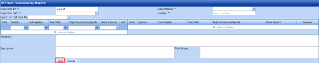
5.36.1 Add an RFI Static Commissioning Request
If you want to add an RFI static commissioning request, do the following steps,
-
In the Sub Contractor box, select a sub-contractor from a drop-down list.
-
In the Inspection Date box, select the date of inspection.
-
In the Location box, enter the name of the location.
Before saving the added RFI static commissioning request, you must add a system. You can add multiple systems for one request.
 Note: The page shows a list of added systems. If you want to view the specific system, use the Search by Test Pack No filter box or use the filter options provided in the System, Sub System, Test Pack, and Check Records columns.
 - Select the checkbox of the respective system which you want to add.
- In the Remarks box, enter your remarks if any.
- In the Description box, enter the description for the request.
- In the Work Scope box, enter the work scope detail.
- Click Save.

The RFI mechanical completion request will be added and listed in the View RFI Static Commissioning page.
5.37 View RFI Static Commissioning
The View RFI Static Commissioning tab helps you to view and edit the RFI static commissioning request, which is added by using the RFI Static Commissioning tab. This tab also allows you to add a new RFI static commissioning request.
- Click View RFI Static Commissioning in the Inspection menu.
The View RFI Static Commissioning List page opens with a list of added RFI static commissioning requests.
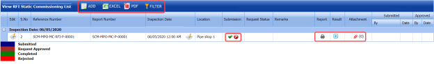
Figure 5.37: View RFI Static Commissioning List page
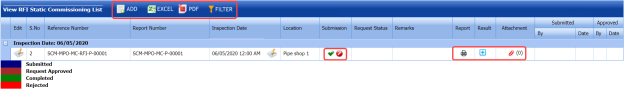
5.37.1 Add an RFI Static Commissioning Request
If you want to add an RFI static commissioning request, do the following steps,
- Click
 (ADD button) in the View RFI Static Commissioning List page.
The system redirects you to a new page to add a new RFI static commissioning request. To know how to add an RFI static commissioning request, See the topic, “Add an RFI Static Commissioning Request”.

Once you have added the RFI static commissioning request, you must submit the added request to perform the static commissioning.
5.37.2 Edit an RFI Static Commissioning Request
If you want to edit any existing static commissioning request in the View RFI Static Commissioning List page, do the following,
-
Click (Edit icon) in the Edit column for the respective RFI static commissioning request. See Fig 5.37.
The RFI Static Commissioning Request page opens with the details of the selected RFI request.
- Click any box where you want to edit the details, and then edit the details in the respective box.
-
Click Save.
5.37.3 Submit and Approve an RFI Static Commissioning Request
Once you have added the RFI static commissioning request, the Submission column in the RFI Static Commissioning Request page is appeared with  (Submit and Reject icons).
-
If you want to submit the static commissioning request, click
 (Submit icon) in the Submission column. Otherwise click
  (Reject icon) to reject the request.
Once you have submitted the static commissioning request, the Request Status column in the View RFI Static Commissioning List page is appeared with
 (Approve and Reject icons).
 - If you want to approve the static commissioning request, click
 (Approve icon) in the Request Status Otherwise click
  (Reject icon) to reject the request.
The static commissioning request will be moved for static commissioning inspection.


5.37.4 Add Results of Static Commissioning Inspection
After completing the static commissioning inspection for the added request, you can add the inspection result details. To add results, do the following steps,
-
Click
 (Add icon) in the Results column of the respective request.
The Result window opens a list of system added for the particular request.

-
In the Result column, select the result of each system from the given result options in the drop-down list.
-
In the Remarks column, enter your remarks if any.
-
Click Approve All & Save.


5.37.5 View a Static Commissioning Inspection Report
If you want to view a static commissioning inspection report, click  (print icon) provided in the Print column of the View RFI Static Commissioning List page. See Fig 5.37.
5.37.6 Attach a File into a Static Commissioning Inspection Request
If you want to attach a file with any existing static commissioning inspection request listed in the View RFI Static Commissioning List page, you can attach the file by using  (Attach icon) in the Attachment column. To know how to attach, follow the procedures given in the topic “Attach a file into P&ID”.
5.37.7 Export Static Commissioning Inspection Request List
You can export a list of static commissioning inspection requests added in the View RFI Static Commissioning List page in both the pdf and excel formats by using  (PDF button) and
  (Excel button). To know how to export, see the topic, “Export P&ID list”.
5.37.8 Filter a Static Commissioning Inspection Request
If you want to filter any specific static commissioning inspection request in the View RFI Static Commissioning List page, you can use  (FILTER button) located on the View RFI Static Commissioning List page. To know how to filter, see the topic, “Filter P&ID”.
5.38 RFI Fit up Generic
The RFI Fit up Request Generic tab in the Inspection menu helps you to add a generic RFI fit up request.
-
Click RFI Fit up Request Generic in the Inspection menu.
The RFI Fit up Request Generic page opens.
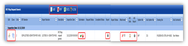
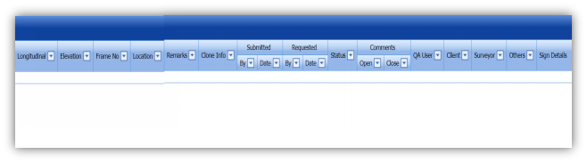
Figure 5.38: RFI Fit up Request Generic page


5.38.1 Add an RFI Fit up Request Generic
If you want to add an RFI fit up request generic, do the following,
- Click
 (ADD button) in the RFI Fit up Request Generic page.
A new window opens to add an RFI fit up request generic.

 Tip: A report number for a new RFI fit up request generic will be updated automatically in the Report Number box.
 - In the Description box, enter the description for the RFI fit up request generic.
- In the System box, select a system from a drop-down list.
- In the Inspection Date box, choose the date of inspection.
- In the Frame No box, enter the frame number.
- In the Elevation box, enter the elevation value.
- In the Longitudinal box, enter the longitudinal value.
- In the Location box, enter the location where the inspection to be done.
- In the Drawing No box, select the drawing number from a drop-down list.
- In the Sub Contractor box, select the sub-contractor from a drop-down list.
- In the Remarks box, enter your remarks if any.
- Click Save.
The RFI fit up request generic is inserted successfully. Once you have added the RFI fit up request generic, you must add the RFI data for the added request.

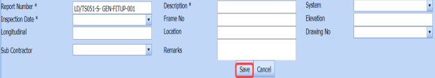

8.38.2 Add RFI data for an Added RFI Fit up Request Generic
If you want to add RFI data for the added RFI fit up request generic, do the following,
- Click
 (Edit icon) in the RFI Data column of the RFI Fit up Request Generic page. See Fig 5.38.
The RFI Inspection Request List window opens.

-
In the Inspection From box, enter the detail from where the inspection should start.
- In the Inspection To box, enter the detail to where the inspection should end.
-
In the Inspection Details option, select 1st Inspection, 2nd Inspection or 3rd Inspection according to the inspection details.
- In the Others box, enter any other inspection related details.
- In the Refer to Report No box, enter the report number for reference.
- In the RFI Date box, choose the RFI date.
-
In the Inspection Result option, if the inspection result is accepted, select Accepted otherwise select Rejected.
-
In the Remarks box, enter your remarks if any.
- In the Inspected by box, enter the name of a person who has done inspection.
- In the Inspected Date box, choose the date of inspection.
- In the Witnessed By box, enter the name of the witnessed person.
- In the Witnessed Date box, choose the date of witnessed.
-
In the PCML Rep Name box, enter the representative name of PCML.
- In the PCML Rep Date box, choose the PCML rep date.
- In the MEB Rep Name box, enter the representative name of MEB.
- In the MEB Rep Date box, choose MEB rep date.
- Click Save.
The RFI data is successfully added.


5.38.3 Clone an RFI Fit up Request Generic
The Clone option in the RFI Fit up Request Generic page used to create a RFI weld VI generic request in the RFI Weld VI Generic page, as a copy of RFI fit up request generic, See Fig 5.39.
If you click  (Clone icon) in the Clone column of the RFI Fit up Request Generic page, an RFI weld VI generic request is added in the RFI weld VI generic page.
 Tip: You can create multiple copies of RFI weld VI generic request for a single RFI fit up request generic.
5.38.4 Print an RFI Report
If you want to print an RFI report, click  (print icon) provided in the RFI Report column of the RFI Fit up Request Generic page. See Fig 5.38.
5.38.5 Submit an RFI Fit up Request Generic
Once you have added the RFI fit up request generic, the Submission column in the RFI Fit up Request Generic page is appeared with  (Submit and Reject icons).
- If you want to submit the RFI fit up request generic, click
 (Submit icon) in the Submission Otherwise click
  (Reject icon) to reject the request.


5.38.6 Print an RFI Fit up Request Generic Report
If you want to print an RFI fit up request generic report, click  (print icon) provided in the Report column of the RFI Fit up Request Generic page. See Fig 5.38.
5.38.7 Attach a File into an RFI Fit up Request Generic
If you want to attach any file with any RFI fit up request generic added in the RFI Fit up Request Generic page, you can attach the file by using  (Attach icon) in the Attachment column. To know how to attach, follow the procedures given in the topic “Attach a file into P&ID”.
5.38.8 View Signature Details of QA User, Surveyor, and Client
Once the RFI fit up inspection has completed, the QA, surveyor, and client add their signature based on their corresponding roles. You can view their signature by using (Sign icon) in the Sign Details column in the RFI Fit up Request Generic page.
5.38.9 Edit an RFI Fit up Request Generic
If you want to edit any existing RFI weld VI generic in the RFI Weld VI Generic page, do the following,
- Click
 (Edit icon) in the Edit column for the respective RFI weld VI generic. See Fig 5.39.
A new window opens to edit the RFI weld VI generic.
- Click any box where you want to edit the details, and then edit the details in the respective box.
-
Click Save.

5.38.10 Export RFI Weld VI Generic List
You can export a list of RFI weld VI generic added in the RFI Weld VI Generic page in the pdf and excel formats by using  (PDF button) and
  (Excel button). To know how to export, see the topic, “Export P&ID list”.
5.38.11 Filter an RFI Weld VI Generic
If you want to filter any RFI weld VI generic from the list of RFI weld VI generic in the RFI Weld VI Generic page, you can use  (FILTER button) located on the View RFI Mechanical Completion List page. To know how to filter, see the topic, “Filter P&ID”.
5.39 RFI Weld VI Generic
Once the RFI fit up inspection process has completed, the materials are moved for weld inspection process. The RFI Weld VI Generic tab in the Inspection menu helps you to add a generic RFI weld VI request.
-
Click RFI Weld VI Generic in the Inspection menu.
The RFI Weld VI Generic page opens.

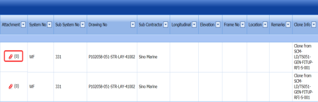
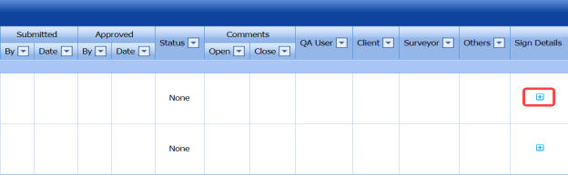
Figure 5.39: RFI Weld VI Generic page
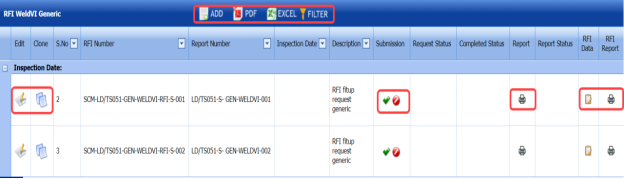


5.39.1 Add an RFI Weld VI Generic
If you want to add an RFI weld VI generic, do the following,
- Click
 (ADD button) in the RFI Weld VI Generic page.
A new window opens to add an RFI weld VI generic.
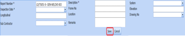
 Note: The fields notified with a symbol (*) are mandatory. You must enter the relevant details in that fields before saving.
 Tip: A report number for a new RFI weld VI generic will be updated automatically in the Report Number box.
 -
In the Description box, enter the description for the RFI weld VI generic.
-
In the System box, select a system from a drop-down list.
-
In the Inspection Date box, choose the date of inspection.
-
In the Frame No box, enter the frame number.
-
In the Elevation box, enter the elevation value.
-
In the Longitudinal box, enter the longitudinal value.
-
In the Location box, enter the location where the inspection to be done.
-
In the Drawing No box, select the drawing number from a drop-down list.
-
In the Sub Contractor box, select the sub-contractor from a drop-down list.
-
In the Remarks box, enter your remarks if any.
-
Click Save.


The RFI weld VI generic is added successfully. Once you have added the RFI weld VI generic, you must add the RFI data for the added request.
5.39.2 Add RFI data for RFI Weld VI Generic
If you want to add RFI data for the added RFI weld VI generic, do the following,
- Click
 (Edit icon) in the RFI Data column of the RFI Weld VI Generic page. See Fig 5.39.
The RFI Inspection Request List window opens.

-
In the Inspection From box, enter the detail from where the inspection should start.
-
In the Inspection To box, enter the detail to where the inspection should end.
- In the Inspection Details option, select 1stInspection, 2nd Inspection or 3rd Inspection according to the inspection details.
-
In the Others box, enter any other inspection related details.
-
In the Refer to Report No box, enter the report number for reference.
-
In the RFI Date box, choose the RFI date.
-
In the Inspection Result option, if the inspection result is accepted, select Accepted otherwise select Rejected.
-
In the Remarks box, enter your remarks if any.
-
In the Inspected by box, enter the name of a person who has done inspection.
-
In the Inspected Date box, choose the date of inspection.
-
In the Witnessed By box, enter the name of the witnessed person.
-
In the Witnessed Date box, choose the date of witnessed.
-
In the PCML Rep Name box, enter the representative name of PCML.
-
In the PCML Rep Date box, choose the PCML rep date.
-
In the MEB Rep Name box, enter the representative name of MEB.
-
In the MEB Rep Date box, choose MEB rep date.
-
Click Save.

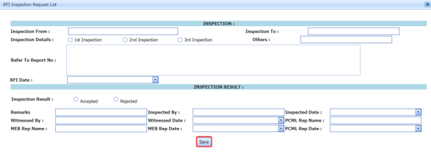
The RFI data is successfully added.
5.39.3 Clone an RFI Weld VI Generic
The Clone option in the RFI Weld VI Generic page used to create a vacuum test request, an air test request, a hydrostatic test request, and an NDT request, as a copy of RFI weld VI generic request.
- Click
 (Clone icon) in the Clone column of the RFI Weld VI Generic page.
The Clone box opens.

- Select any test from the given list.
-
Click
 (Add button).
A new request for the selected test will be added in the respective pages.

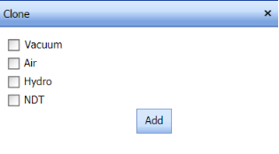

5.39.4 Print an RFI Report
If you want to print an RFI report, click (print icon) provided in the RFI Report column of the RFI Weld VI Generic page. See Fig 5.39.
5.39.5 Submit an RFI Weld VI Generic
Once you have added the RFI weld VI generic, the Submission column in the RFI Weld VI Generic page is appeared with (Submit and Reject icons).
- If you want to submit the RFI weld VI generic, click
 (Submit icon) in the Submission Otherwise click
 (Reject icon) to reject the request.


5.39.6 Print an RFI Weld VI Generic Report
- If you want to print an RFI weld VI generic report, click
 (print icon) provided in the Report column of the RFI Weld VI Generic See Fig 5.39.

5.39.7 View Signature Details of QA User, Surveyor, and Client
Once the weld VI inspection has completed, the QA, surveyor, and client add their signature based on their corresponding roles. You can view their signature by using (Sign icon) in the Sign Details column in the RFI Weld VI Generic page.
5.39.8 Attach a File into an RFI Weld VI Generic
If you want to attach any file with any RFI weld VI generic added in the RFI Weld VI Generic page, you can attach the file by using (Attach icon) in the Attachment column. To know how to attach, follow the procedures given in the topic “Attach a file into P&ID”.
5.39.9 Edit an RFI Weld VI Generic
If you want to edit any existing RFI weld VI generic in the RFI Weld VI Generic page, do the following,
- Click
 (Edit icon) in the Edit column for the respective RFI weld VI generic. See Fig 5.39.
A new window opens to edit the RFI weld VI generic.
- Click any box where you want to edit the details, and then edit the details in the respective box.
-
Click Save.

5.39.10 Export RFI Weld VI Generic List
You can export a list of RFI weld VI generic added in the RFI Weld VI Generic page in the pdf and excel formats by using  (PDF button) and
  (Excel button). To know how to export, see the topic, “Export P&ID list”.
5.39.11 Filter an RFI Weld VI Generic
If you want to filter any RFI weld VI generic from the list of RFI weld VI generic in the RFI Weld VI Generic page, you can use (FILTER button) located on the View RFI Mechanical Completion List page. To know how to filter, see the topic, “Filter P&ID”.
5.40 NDT Inspection Generic
NDT inspection used to find out welding defects of the materials. Once the fit up and welding process of the materials has completed, the materials will be moved for the NDT inspection. The currently following NDT inspection methods are RT, UT, MT, PT, Ultrasonic Thickness Gaging (UTG), Magnetic Particle Inspection (MPI) after load test, UT/MT, and PT after load test.
The NDT Inspection Generic tab in the Inspection menu helps you to add an NDT inspection generic. If you want to navigate the NDT inspection generic,
- Click NDT Inspection Generic in the Inspection menu.
The NDT Inspection Generic page opens.
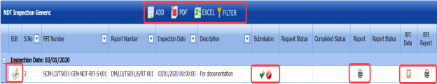

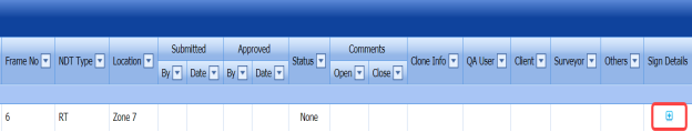
Figure 5.40: NDT Inspection Generic page
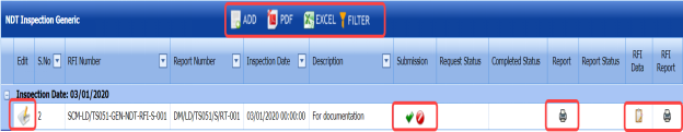
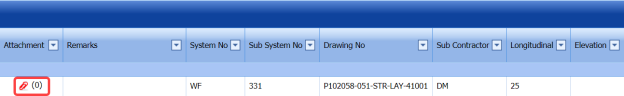

5.40.1 Add an NDT Inspection Generic
If you want to add an NDT inspection generic, do the following,
- Click
 (ADD button) in the NDT Inspection Generic page.
A new window opens to add an NDT Inspection generic.

 Note: The fields notified with a symbol (*) are mandatory. You must enter the relevant details in that fields before saving.
 Tip: A report number for a new NDT inspection generic will be updated automatically in the Report Number box.
 - In the Description box, enter the description for the NDT inspection generic.
-
In the System box, select a system from a drop-down list.
-
In the Inspection Date box, choose the date of inspection.
-
In the Frame No box, enter the frame number.
-
In the Elevation box, enter the elevation value.
-
In the Longitudinal box, enter the longitudinal value.
-
In the Location box, enter the location where the inspection to be done.
-
In the Drawing No box, select the drawing number from a drop-down list.
-
In the Designation box, enter the designation detail.
-
In the Cost Centre box, enter the cost centre detail.
-
In the Requisition box, select the type of request from a drop-down list.
-
In the Welding Position box, enter the position of welding.
-
In the Weld Type box, enter the type of welding.
-
In the Thickness box, enter the thickness of the welding.
-
In the Sub Contractor box, select the sub-contractor from a drop-down list.
-
In the Welder box, select the name of a welder from a drop-down list.
-
In the WPS box, enter the WPS detail.
-
In the Process box, select the welding process to be done from a specified category.
-
In the NDT Type box, select the type of NDT to be done from a specified category.
-
In the Remarks box, enter your remarks if any.
-
Click Save.

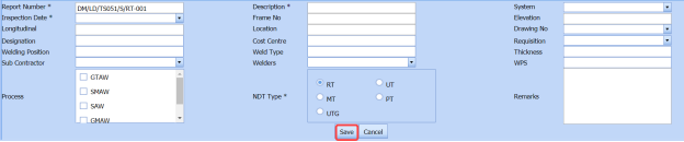


The NDT inspection generic is added successfully. Once you have added the NDT inspection generic, you must add the RFI data for the added NDT inspection generic.
5.40.2 Add RFI Data for NDT Inspection Generic
If you want to add RFI data for the added NDT inspection generic, do the following,
- Click
 (Edit icon) in the RFI Data column of the NDT Inspection Generic See Fig 5.40.
The RFI Inspection Request List window opens.

- In the Inspection From box, enter the detail from where the inspection should start.
-
In the Inspection To box, enter the detail to where the inspection should end.
- In the Inspection Details option, select 1stInspection, 2nd Inspection or 3rd Inspection according to the inspection details.
- In the Others box, enter any other inspection related details.
-
In the Refer to Report No box, enter the report number for reference.
-
In the RFI Date box, choose the RFI date.
- In the Inspection Result option, if the inspection result is accepted, select Accepted otherwise select Rejected.
- In the Remarks box, enter your remarks if any.
- In the Inspected by box, enter the name of a person who has done inspection.
- In the Inspected Date box, choose the date of inspection.
- In the Witnessed By box, enter the name of the witnessed person.
- In the Witnessed Date box, choose the date of witnessed.
- In the PCML Rep Name box, enter the representative name of PCML.
- In the PCML Rep Date box, choose the PCML rep date.
- In the MEB Rep Name box, enter the representative name of MEB.
- In the MEB Rep Date box, choose MEB rep date.
- Click Save.
The RFI data is successfully added.


5.40.3 Print an RFI Report
If you want to print an RFI report, click  (print icon) provided in the RFI Report column of the NDT Inspection Generic page. See Fig 5.40.
5.40.4 Submit an NDT Inspection Generic
Once you have added the NDT inspection generic, the Submission column in the NDT Inspection Generic page is appeared with (Submit and Reject icons).
-
If you want to submit the added NDT inspection generic, click
 (Submit icon) in the Submission column. Otherwise click
  (Reject icon) to reject the request.


5.40.5 Print an NDT Inspection Generic Report
If you want to print an NDT inspection generic report, click (print icon) provided in the Report column of the NDT Inspection Generic page. See Fig 5.40.
5.40.6 View Signature Details of QA User, Surveyor, and Client
Once the NDT inspection has completed, the QA, surveyor, and client add their signature based on their corresponding roles. You can view their signature by using  (Sign icon) in the Sign Details column in the NDT Inspection Generic page.
5.40.7 Attach a File into an NDT Inspection Generic
If you want to attach any file with any NDT inspection generic added in the NDT Inspection Generic page, you can attach the file by using  (Attach icon) in the Attachment column. To know how to attach, follow the procedures given in the topic “Attach a file into P&ID”.
5.40.8 Edit an NDT Inspection Generic
If you want to edit any existing NDT inspection generic in the NDT Inspection Generic page, do the following,
- Click
 (Edit icon) in the Edit column for the respective NDT inspection generic. See Fig 5.40.
A new window opens to edit the NDT inspection generic.
-
Click any box where you want to edit the details, and then edit the details in the respective box.
-
Click Save.

5.40.9 Export NDT Inspection Generic List
You can export a list of NDT inspection generic added in the NDT Inspection Generic page in the pdf and excel formats by using  (PDF button) and
  (Excel button). To know how to export, see the topic, “Export P&ID list”.
5.40.10 Filter an NDT Inspection Generic
If you want to filter any NDT inspection generic from the list of NDT inspection generic in the NDT Inspection Generic page, you can use  (FILTER button) located on the NDT Inspection Generic page. To know how to filter, see the topic, “Filter P&ID”.
5.41 View RFI Fit up (Unique Numbers)
The View RFI Fit up tab helps you to add a new RFI fit up request. This tab also allows you to view and edit the added RFI fit up request.
-
Click View RFI Fit up in the Inspection menu.
The RFI Fit up Requests List page opens.
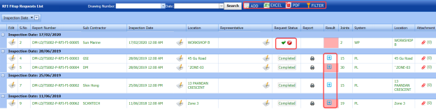
Figure 5.41: RFI Fit up Requests List page
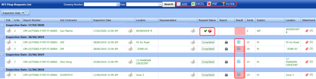
5.41.1 Add an RFI Fit up Request
If you want to add an RFI fit up request, do the following,
- Click
 (ADD button) in the RFI Fit up Requests List page.
A new page opens to add an RFI fit up request.
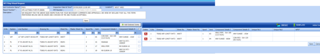
Figure 5.41.1: A page for adding an RFI fit up request
 Tip: A report number and an RFI number for a new RFI fit up request will be updated automatically in the Report Number and the RFI Number boxes, respectively.
 - In the Sub Contractor box, select the name of a sub-contractor from a drop-down list.
- In the Inspection Date & Time box, select the date of inspection.
 Note: The fit up inspection date should not be later than the RFI weld visual inspection date.
 - In the Location box, enter the location detail.
-
In the Description box, enter the description for the inspection.
 Note: Before saving the added RFI fit up request, you must add the joints. You can add multiple joints for any added fit up request by using a box provided in the left side of the page.
 -
Click Save.


5.41.2 Add Joints for an RFI Fit up Request
If you want to add joints for any added RFI fit up request, do the following steps,
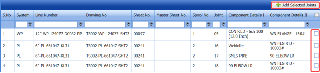
- Click the check box of the respective joints.
- Click
 (Add Selected Joints button).
The selected joints are moved into the Added Joints box located in the right side of the page.
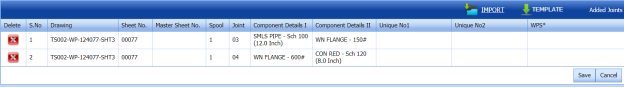
-
If you want to update the unique numbers and WPS number for any joint, click the Unique No and WPS Number columns for the respective joints and then enter the unique numbers and select the WPS number from a drop-down list.
-
Click Save.
The selected joints are successfully added for the RFI fit up request.


5.41.3 Import Multiple Joints for an RFI Fit up Request
If you want to import multiple joints together, do the following,
-
Click
 (TEMPLATE button) on the Added Joints box.
A template will be downloaded as an excel worksheet to enter the details of multiple joints.
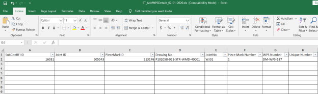
-
Enter the relevant details in the required columns on the excel worksheet.
-
Once you have added the joint details in the excel worksheet, save the excel worksheet on your computer.
- Click
 (IMPORT button).
A new window opens for importing the excel worksheet saved on your computer.

-
Click
 (Browse button) to select the excel worksheet to be uploaded.
 - Select the excel worksheet you want to upload from your computer.
- Click
 (Upload button) to export the joints that are included in the excel worksheet.


The details of the joints in the worksheet will be displayed in the page.
The RFI fit up request is added successfully. Once you have added the RFI fit up request, you must submit the added request for inspection.
5.41.4 Submit an RFI Fit up Request
Once you have added the RFI fit up request, the Request Status column in the RFI Fit up Requests List page is appeared with  (Submit and Reject icons). See Fig 5.41.
- If you want to submit the RFI fit up request, click
 (Submit icon) in the Request Status Otherwise click
  (Reject icon) to reject the request.


5.41.5 Change a Representative for Any RFI Fit up Request
If you want to change a representative for any added RFI fit up request,
-
Click
 (Edit icon) in the Representative column for the respective RFI fit up request.
The Edit Form window opens.

-
In the Representative box, enter the name of a representative.
- Click Save.

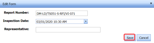
5.41.6 Print an RFI Fit up Report
If you want to print an RFI fit up report, click  (print icon) provided in the Report column of the RFI Fit up Requests List page. See Fig 5.41.
5.41.7 Add Result for an Added RFI Fit up Request
Once you have fit up inspection, you can add the results. To add results,
-
Click
 (Add icon) in the Results column of the RFI Fit up Requests List page.
The Result window opens.

-
If you want to check and update the unique number details for both the components, click
 (Edit icon) in the Update Unique Number 1 and Update Unique Number 2 columns and update.
 -
If you want to update the WPS number, select the respective number in the WPS column and change the WPS number from a drop-down list.
- If you want to update the result, select the respective result in the Result column from a drop-down list.
- In the Remarks box, enter your remarks if any.
- Click Save changes.

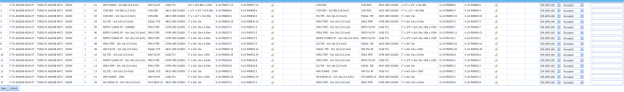

5.41.8 Attach a File into an RFI Fit up Request
If you want to attach any file with any RFI fit up request listed in the RFI Fit up Requests List page, you can attach the file by using  (Attach icon) in the Attachment column. To know how to attach, follow the procedures given in the topic “Attach a file into P&ID”.
5.41.9 Edit an RFI Fit up Request
If you want to edit any existing RFI fit up request in the RFI Fit up Requests List page, do the following,
- Click
 (Edit icon) in the Edit column for the respective RFI fit up request. See Fig 5.41.
A new page opens to edit the RFI fit up request.
- Click any box where you want to edit the details, and then edit the details in the respective box.
-
Click Save.

5.41.10 Export RFI Fit up Request List
You can export a list of RFI fit up request added in the RFI Fit up Requests List page in the pdf and excel formats by using  (PDF button) and
  (Excel button). To know how to export, see the topic, “Export P&ID list”.
5.41.11 Filter an RFI Fit Up Request
If you want to filter any RFI fit up request from the list of RFI fit up requests in the RFI Fit up Requests List page, you can use  (FILTER button). To know how to filter, see the topic, “Filter P&ID”.
5.42 View RFI Weld VI (Unique Numbers)
The View RFI Weld VI tab helps you to add a new RFI weld VI request. This tab also allows you to view and edit the added RFI weld VI request.
-
Click View RFI Weld VI in the Inspection menu.
The RFI Weld Visual Request List page opens.
Figure 5.42: RFI Weld Visual Request List page

8.42.1 Add an RFI Weld VI Request
If you want to add an RFI weld VI request, do the following,
- Click
 (ADD button) in the RFI Weld Visual Request List Page.
A new page opens to add an RFI weld VI request.

 Tip: A report number and an RFI number for a new RFI weld VI request will be updated automatically in the Report Number and the RFI Number boxes, respectively.
 - In the Sub Contractor box, select the name of a sub-contractor from a drop-down list.
- In the Inspection Date & Time box, select the date of inspection.
- In the Location box, enter the location detail.
 Note: Before saving the added RFI weld VI request, you must add the joints. You can add multiple joints for any added RFI weld VI request by using a box provided in the left side of the RFI Weld Visual Request page.
 -
Click Save.


5.42.2 Add Joints for an RFI Weld VI Request
If you want to add joints for any added RFI weld VI request, do the following,
- In the RFI Report Number box, select an RFI report number from a drop-down list.
A list of joints including the ISO drawing and spool numbers opens for the selected RFI report number.
- Click the check box of the respective joints.
- Click
 (Add Selected Joints button).
The selected joints are moved into the Added Joints box located in the right side of the page.

-
If you want to update the WPS number for any joint, click the WPS Number column for the respective joints and then select the WPS number from a drop-down list.
-
If you want to update the welder details, click
 (Add icon) in the Welder Details column.
The Weld-Weld Layer- Weld Process window opens.
- In the Date box, select the date of adding welder details.
- In the Weld Process column, select a weld process.
- In the Weld Position column, select a weld position.
- In the Weld Layers column, select a weld layer.
A list of welders will be displayed in the Welder Number/Name column for the selected criteria.
- Select a welder you want to add.
- Click
 (Add button).
The selected welder details will be listed below.
 Note: If you want to add welder details for the next joint, click
  (Next Joint button).
 - Click Save.
The selected joints are successfully added for the RFI weld VI request.

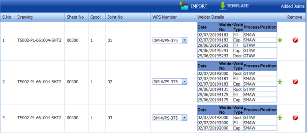


5.42.3 Import Multiple joints for an RFI Weld VI Request
You can import multiple joints together by using a pre-defined excel template given in the application. If you want to import multiple joints together, do the following,
- Click
 (TEMPLATE button) on the Added Joints box.
A template will be downloaded as an excel worksheet to enter the details of multiple joints.

- Enter the relevant details in the required columns on the excel worksheet.
- Once you have added the joint details in the excel worksheet, save the excel worksheet on your computer.
- Click
 (IMPORT button).
A new window opens for importing the excel worksheet saved on your computer.

- Click
 (Browse button) to select the excel worksheet to be uploaded.
 -
Select the excel worksheet you want to upload from your computer.
- Click
 (Upload button) to export the joints that are included in the excel worksheet.
The details of the joints in the worksheet will be displayed in the page.


The RFI weld VI request is added successfully. Once you have added the RFI weld VI request, you must submit the added request for inspection.
5.42.4 Submit an RFI Weld VI Request
Once you have added the RFI weld VI request, the Request Status column in the RFI Weld Visual Request List page is appeared  with (Submit and Reject icons). See Fig 5.42.
-
If you want to submit the RFI weld VI request, click
 (Submit icon) in the Request Status column. Otherwise click
  (Reject icon) to reject the request.


5.42.5 Add a Representative for Any RFI Weld VI Request
If you want to add a representative for any added RFI weld VI request,
- Click
 (Edit icon) in the Representative column for the respective RFI weld VI request.
The Edit Form window opens.

-
In the Representative box, enter the name of a representative.
-
Click Save.


5.42.6 Add Result for an RFI Weld VI Request
If you want to add for the added RFI weld VI inspection request, do the following,
- Click
 (Add icon) in the Results column of the RFI Weld Visual Request List page, for the respective RFI weld VI request. See Fig 5.42.
A new window opens including the line, drawing number, joint number and WPS number including welder details for the respective RFI weld VI request.
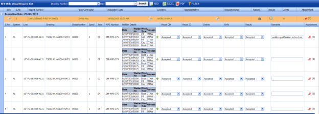
-
If you want to update the welder details, click
 (Add icon) in the Welder Details column and update the welder details.
 -
In the Visual OD column, select the result for visual OD.
-
In the Visual ID column, select the result for visual ID.
- In the Debris column, select the result for debris.
- In the Drift column, select the result for drift.
- In the Result column, select the results from a drop-down list based on your inspection.
-
In the Remarks column, enter your remarks if any.
-
Click Save.


5.42.7 Print an RFI Weld VI Request
If you want to print an RFI weld VI report, click  (print icon) provided in the Report column of the RFI Weld Visual Request List page. See Fig 5.42.
5.42.8 Attach a File into an RFI Weld VI Request
If you want to attach any file with any RFI weld VI request listed in the RFI Weld Visual Request List page, you can attach the file by using  (Attach icon) in the Attachment column. To know how to attach, follow the procedures given in the topic “Attach a file into P&ID”.
5.42.9 Edit an RFI Weld VI Request
If you want to edit any existing RFI weld VI request in the RFI Weld Visual Request List page, do the following,
-
Click
 (Edit icon) in the Edit column for the respective RFI weld VI request. See Fig 5.42.
A new page opens to edit the RFI weld VI request.
-
Click any box where you want to edit the details, and then edit the details in the respective box.
- Click Save.

5.42.10 Export RFI Weld VI Request List
You can export a list of RFI weld VI request added in the RFI Weld Visual Request List page in the pdf and excel formats by using  (PDF button) and
  (Excel button). To know how to export, see the topic, “Export P&ID list”.
5.42.11 Filter an RFI Weld VI Request
If you want to filter any RFI weld VI request from the list of RFI weld VI requests in the RFI Weld Visual Request List page, you can use  (FILTER button). To know how to filter, see the topic, “Filter P&ID”.
5.43 View AFI Fit up (Unique Numbers)
The View AFI Fit up allows you to add a new AFI fit up request. This tab also helps you to view and edit the added AFI fit up request.
-
Click View AFI Fit up in the Inspection menu.
The AFI Fit up Request List page opens.

Figure 5.43: AFI Fit up Request List page
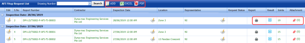
5.43.1 Add an AFI Fit up Request
If you want to add an AFI fit up request, do the following,
-
Click
 (ADD button) in the AFI Fit up Request List page.
The AFI Fit up Inspection Request page opens to add an AFI fit up request.
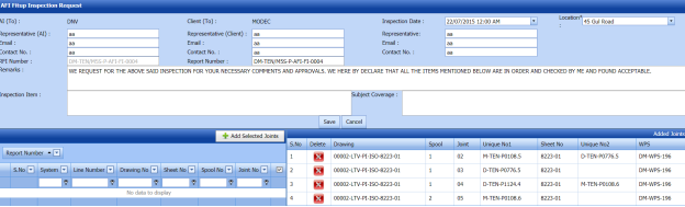


 Tip: A report number and RFI number for a new AFI fit up request will be updated automatically in the Report Number and RFI Number boxes.
- In the Representative (AI) box, enter representative name for the application inspection and enter their email id and contact number in the Email and Contact No boxes, respectively.
-
In the Representative (Client) box, enter representative name from the client and enter their email id and contact number in the Email and Contact No boxes, respectively.
- In the Inspection Date box, select the date of inspection.
- In the Representative (Contractor) box, enter representative name from the contractor and enter their email id and contact number in the Email and Contact No boxes, respectively.
-
In the Location box, enter the location detail.
-
In the Remarks box, enter your remarks if any.
-
In the Inspection Item box, enter the details of items to be inspected.
-
In the Subject Coverage box, enter the subject coverage detail.
 Note: Before saving the added AFI fit up request, you must add the joints. You can add multiple joints for any added fit up request by using a box provided in the left side of the page.
 -
Click Save.
Once you enter the details to add an AFI fit up request, a list of joints including the joint numbers, sheet numbers, and spool and drawing numbers opens.

5.43.2 Add Joints for an AFI Fit up Request
If you want to add joints for any added AFI fit up request, do the following,
- Click the check box of the respective joints.
- Click
 (Add Selected Joints button).
The selected joints are moved into the Added Joints box located in the right side of the page.
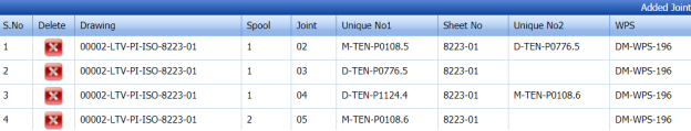


The selected joints are successfully added for the AFI fit up request.
Once you have added the RFI fit up request, you must submit the added request for inspection.
5.43.3 Submit an AFI Fit up Request
Once you have added the AFI fit up request, the Request Status column in the AFI Fit up Request List page is appeared with  (Submit and Reject icons). See Fig 5.43.
- If you want to submit the AFI fit up request, click
 (Submit icon) in the Request Status Otherwise click
  (Reject icon) to reject the request.


5.43.4 Change Representative for Any AFI Fit up Request
If you want to change the added representative for any AFI fit up request,
- Click
 (Edit icon) in the Representative column for the respective AFI fit up request.
The Edit Form window opens.
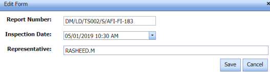
- In the Representative box, edit the name of a representative.
-
Click Save.


5.43.5 Print an AFI Fit up Report
If you want to print an AFI fit up report, click  (print icon) provided in the Report column of the AFI Fit up Request List page. See Fig 5.43.
5.43.6 Add Result of AFI Fit up Inspection
If you want to update results for the AFI fit up inspection request, do the following,
- Click
 (Add icon) in the Results column of the AFI Fit up Request List page.
A new window opens.

-
In the Result column, select the results of AFI inspection from a drop-down list, for the respective drawing and joint numbers.
-
In the Remarks column, enter your remarks if any.
-
Click Save.

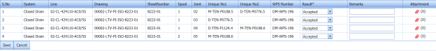
5.43.7 Attach a File into an AFI Fit up Request
If you want to attach any file with any AFI fit up request listed in the AFI Fit up Request List page, you can attach the file by using  (Attach icon) in the Attachment column. To know how to attach, follow the procedures given in the topic “Attach a file into P&ID”.
5.43.8 Edit an AFI Fit up Request
If you want to edit any existing AFI fit up request in the AFI Fit up Request List page, do the following,
-
Click
 (Edit icon) in the Edit column for the respective AFI fit up request. See Fig 5.43.
A new page opens to edit the AFI fit up request.
-
Click any box where you want to edit the details, and then edit the details in the respective box.
- Click Save.

5.43.9 Export AFI Fit up Request List
You can export a list of AFI fit up request added in the AFI Fit up Request List page in the pdf and excel formats by using  (PDF button) and
  Excel button). To know how to export, see the topic, “Export P&ID list”.
8.44 View AFI Weld VI (Unique Numbers)
The View AFI Weld VI allows you to add a new AFI weld VI request. This tab also helps you to view and edit the added AFI weld VI request.
-
Click View AFI Weld VI in the Inspection menu.
The AFI Weld Visual Request List page opens.

Figure 5.44: AFI Weld Visual Request List page
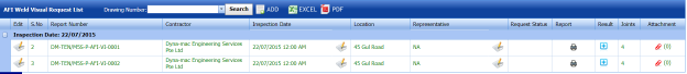
8.44.1 Add an AFI Weld VI Request
If you want to add an AFI weld VI request, do the following,
-
Click
 (ADD button) in the AFI Weld Visual Request List page.
The AFI Weld Visual Inspection Request page opens to add an AFI weld VI request.

 Tip: A report number and RFI number for a new AFI weld VI request will be updated automatically in the Report Number and RFI Number boxes.
 - In the Representative (AI) box, enter representative name for the application inspection and enter their email id and contact number in the Email and Contact No boxes, respectively.
- In the Representative (Client) box, enter representative name from the client and enter their email id and contact number in the Email and Contact No boxes, respectively.
- In the Inspection Date box, select the date of inspection.
-
In the Representative (Contractor) box, enter representative name from the contractor and enter their email id and contact number in the Email and Contact No boxes, respectively.
- In the Inspection Item box, enter the details of items to be inspected.
- In the Subject Coverage box, enter the subject coverage detail.
- In the Remarks box, enter your remarks if any.
 Note: Before saving the added AFI weld VI request, you must add the joints. You can add multiple joints for any added weld VI request by using a box provided in the left side of the page.
 -
Click Save.

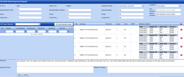


5.44.2 Add Joints for an AFI Weld VI Request
If you want to add joints for any added AFI weld VI request, do the following,
-
Click the check box of the respective joints.
- Click
 (Add Selected Joints button).
The selected joints are moved into the Added Joints box located in the right side of the page.
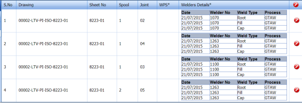
- Click Save.


The selected joints are successfully added for the AFI weld VI request.
The AFI weld VI request is successfully added. Once you have added the AFI weld VI request, you must submit the added weld VI request for inspection.
5.44.3 Submit an AFI Weld VI Request
Once you have added the AFI weld VI request, the Request Status column in the AFI Weld Visual Request List page is appeared with  (Submit and Reject icons). See Fig 5.44.
- If you want to submit the RFI weld VI request, click
 (Submit icon) in the Request Status Otherwise click
  (Reject icon) to reject the request.


5.44.4 Change a Representative for Any AFI Weld VI Request
If you want to change a representative for any added AFI weld VI request,
- Click
 (Edit icon) in the Representative column for the respective AFI weld VI request.
The Edit Form window opens.

-
In the Representative box, enter the name of a representative.
- Click Save.

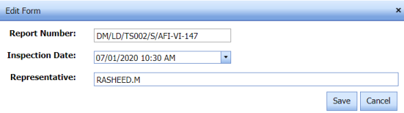
5.44.5 Add Result for an AFI Weld VI Inspection
If you want to add result for the added AFI weld VI inspection, do the following,
- Click
 (Add icon) in the Results column of the AFI Weld Visual Request List page, for the respective AFI weld VI request. See Fig 5.44.
A new window opens including the line, drawing numbers and joint number for the respective AFI weld VI request.
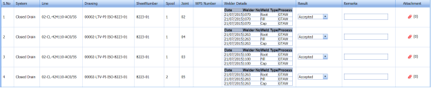
- In the Result column, select the results from a drop-down list based on your inspection.
- In the Remarks column, enter your remarks if any.
- Click Save.


5.44.6 Print an AFI Weld VI Report
If you want to print an AFI weld VI report, click (print icon) provided in the Report column of the AFI Weld Visual Request List page. See Fig 5.44.
5.44.7 Attach a file into an AFI weld VI request
If you want to attach any file with any AFI weld VI request listed in the AFI Weld Visual Request List page, you can attach the file by using  (Attach icon) in the Attachment column. To know how to attach, follow the procedures given in the topic “Attach a file into P&ID”.
5.44.8 Edit an AFI Weld VI Request
If you want to edit any existing AFI weld VI request in the AFI Weld Visual Request List page, do the following steps,
-
Click
 (Edit icon) in the Edit column for the respective AFI weld VI request. See Fig 5.44.
A new page opens to edit the AFI weld VI request.
-
Click any box where you want to edit the details, and then edit the details in the respective box.
-
Click Save.

5.44.9 Export AFI Weld VI Request List
You can export a list of AFI weld VI request added in the AFI Weld Visual Request List page in the pdf and excel formats by using (PDF button) and
  (Excel button). To know how to export, see the topic, “Export P&ID list”.
5.44.10 Filter an AFI weld VI request
If you want to filter any AFI weld VI request from the list of AFI weld VI requests in the AFI Weld Visual Request List page, you can use  (FILTER button). To know how to filter, see the topic, “Filter P&ID”.
5.45 RFI Line Walk
The RFI Line Walk tab in the Inspection menu is used to add a request for line walk inspection.
5.45.1 Add a Line Walk Inspection Request
If you want to add a line walk inspection request, do the following steps,
- Click RFI Line Walk in the Inspection menu.
The RFI Line Walk page opens.
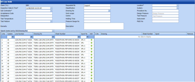
Figure 5.45: RFI Line Walk page
- In the Requested By box, enter the name of a person who has requested the line walk inspection.
- In the Location box, select the location where the inspection to be performed.
- In the Inspection Date & Time box, select the inspection date and time.
- In the Classification box, enter the classification detail.
- In the System box, select a system from a drop-down list.
- In the Sub Contractor box, select a sub-contractor from a drop-down list.
- In the Acceptance Code box, enter the acceptance code detail.
- In the Designation box, enter the designation detail.
- In the Test Temperature box, enter the test temperature value.
- In the Test Medium box, select the test medium from the drop-down list.
-
In the Drawing No box, select the drawing number from a drop-down list.
- In the Work Scope box, enter the work scope detail.
- In the Cost Centre box, enter the cost centre detail.
- In the Holding Timebox, enter the holding time range.
- In the Pressure Gauge No box, enter the pressure gauge number.
- In the Procedure No box, enter the procedure number.
-
In the Design Pressure box, enter the design pressure range.
- In the Test Pressure box, enter the test pressure range.
- In the Instrument box, enter the instrument name.
- In the P&ID No box, enter the P&ID number.
- In the Remarks box, enter your remarks if any.
- In the Description box, enter the description for the line walk inspection.
Before saving the added line walk inspection request, you must add spools.
 Note: You can add multiple spools for one request.
The RFI Line Walk page shows a list of added spools. If you want to view the spools for the specific ISO drawing, select the respective ISO drawing from a drop-down list.

- Click
 (Add icon) of the respective spool which you want to add.
The added spools will be moved to the right side of the page.
-
Click Save Request.


The line walk inspection request will be added and listed in the RFI Line Walk Report page.
5.46 View RFI Line Walk
The View RFI Line Walk tab helps you to view and edit the line walk inspection request, which is added by using the RFI Line Walk tab. This tab also allows you to add a new line walk inspection request.
- Click View RFI Line Walk in the Inspection menu.
The RFI Line Walk Report page opens with a list of added line walk inspection requests.
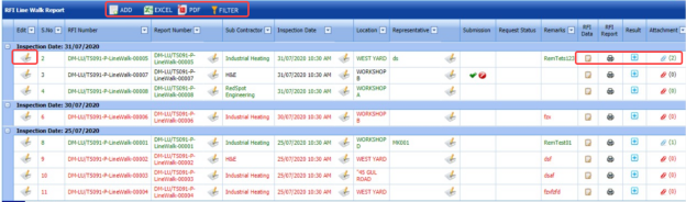
Figure 5.46: RFI Line Walk Report page

5.46.1 Add a Line Walk Inspection Request
If you want to add a line walk inspection request, do the following steps,
Once you have added the line walk inspection request, you must submit the added request to perform the line walk inspection.
5.46.2 Add Representative for a Line Walk Inspection Request
If you want to add a representative for any added line walk inspection request,
- Click (Edit icon) in the Representative column for the respective line walk inspection request.
The Edit Form window opens.

- In the Representative box, enter the name of a representative.
- In the Inspection Date box, select the date of inspection.
- In the Remarks box, enter your remarks if any.
- Click Save.

5.46.3 Edit a Line Walk Inspection Request
If you want to edit any existing line walk inspection request in the RFI Line Walk Report page, do the following,
- Click
 (Edit icon) in the Edit column for the respective line walk inspection request. See Fig 5.46.
The RFI Line Walk Report page opens with the details of the selected line walk inspection request.
- Click any box where you want to edit the details, and then edit the details in the respective box.
- Click Save.

5.46.4 Submit and Approve a Line Walk Inspection Request
Once you have added the line walk inspection request, the Submission column in the RFI Line Walk Report page is appeared with  (Submit and Reject icons).
-
If you want to submit the line walk inspection request, click
 (Submit icon) in the Submission column. Otherwise click
  (Reject icon) to reject the request.
Once you have submitted the line walk inspection request, the Request Status column in the RFI Line Walk Report page is appeared with
 (Approve and Reject icons).
 - If you want to approve the line walk inspection request, click
 (Approve icon) in the Request Status Otherwise click
 (Reject icon) to reject the request.


The line walk inspection request will be moved for line walk inspection.
5.46.5 Add RFI Data for a Line Walk Inspection Request
If you want to add RFI data for the added line walk inspection request, do the following,
- Click
 (Edit icon) in the RFI Data column of the RFI Line Walk Report See Fig 5.46.
The RFI Inspection Request List window opens.

-
In the Inspection From box, enter the detail from where the inspection should start.
- In the Inspection To box, enter the detail to where the inspection should end.
-
In the Inspection Details option, select 1st Inspection, 2nd Inspection or 3rd Inspection according to the inspection details.
- In the Others box, enter any other inspection related details.
- In the Refer to Report No box, enter the report number for reference.
- In the RFI Date box, choose the RFI date.
-
In the Inspection Result option, if the inspection result is accepted, select Accepted otherwise select Rejected.
- In the Remarks box, enter your remarks if any.
- In the Inspected by box, enter the name of a person who has done inspection.
- In the Inspected Date box, choose the date of inspection.
- In the Witnessed By box, enter the name of the witnessed person.
- In the Witnessed Date box, choose the date of witnessed.
- In the PCML Rep Name box, enter the representative name of PCML.
- In the PCML Rep Date box, choose the PCML rep date.
- In the MEB Rep Name box, enter the representative name of MEB.
- In the MEB Rep Date box, choose MEB rep date.
-
Click Save.


The RFI data is successfully added.
5.46.6 View an RFI Report
If you want to view an RFI report, click  (print icon) provided in the RFI Report column of the RFI Line Walk Report page. See Fig 5.46.
5.46.7 Add Results of Line Walk Inspection
After completing the line walk inspection for the added request, you can add the inspection result details. To add results, do the following steps,
- Click
 (Add icon) in the Results column of the respective request.
The Result window opens a list of spools added for the particular request.
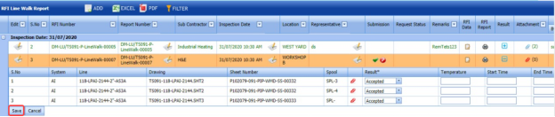
- In the Result column, select the result of each spool from the given result options in the drop-down list.
- In the Temperature column, enter the temperature value of each spool.
- In the Start Time and End Time columns, enter the start and end times.
- Click Save.


5.46.8 Attach a File into a Line Walk Inspection Request
If you want to attach a file with any existing line walk inspection request listed in the RFI Line Walk Report page, you can attach the file by using  (Attach icon) in the Attachment column. To know how to attach, follow the procedures given in the topic “Attach a file into P&ID”.
5.46.9 Export Line Walk Inspection Request List
You can export a list of line walk inspection requests added in the RFI Line Walk Report page in both the pdf and excel formats by using  (PDF button) and
  (Excel button). To know how to export, see the topic, “Export P&ID list”.
5.46.10 Filter a Line Walk Inspection Request
If you want to filter any specific line walk inspection request in the RFI Line Walk Report page, you can use  (FILTER button) located on the RFI Line Walk Report page. To know how to filter, see the topic, “Filter P&ID”.
5.47 RFI Flushing
The RFI Flushing tab in the Inspection menu is used to add a request for pipe flushing inspection.
5.47.1 Add a Flushing Inspection Request
If you want to add a flushing inspection request, do the following steps,
- Click RFI Flushing in the Inspection menu.
The RFI Flushing page opens.

Figure 5.47: RFI Flushing page
- In the Requested By box, enter the name of a person who has requested the flushing inspection.
- In the Location box, select the location where the inspection to be performed.
- In the Inspection Date & Timebox, select the inspection date and time.
- In the Classification box, enter the classification detail.
- In the System box, select a system from a drop-down list.
- In the Sub Contractor box, select a sub-contractor from a drop-down list.
- In the Acceptance Code box, enter the acceptance code detail.
- In the Designation box, enter the designation detail.
- In the Test Temperature box, enter the test temperature value.
- In the Test Medium box, select the test medium from the drop-down list.
-
In the Drawing No box, select the drawing number from a drop-down list.
-
In the Work Scope box, enter the work scope detail.
-
In the Cost Centre box, enter the cost centre detail.
-
In the Holding Time box, enter the holding time range.
-
In the Pressure Gauge No box, enter the pressure gauge number.
-
In the Procedure No box, enter the procedure number.
-
In the Design Pressure box, enter the design pressure range.
-
In the Test Pressure box, enter the test pressure range.
-
In the Instrument box, enter the instrument name.
-
In the P&ID No box, enter the P&ID number.
-
In the Remarks box, enter your remarks if any.
-
In the Description box, enter the description for the flushing inspection.
Before saving the added flushing inspection request, you must add spools.
The RFI Flushing page shows a list of added spools. If you want to view the spools for the specific ISO drawing, select the respective ISO drawing from a drop-down list. Note: You can add multiple spools for one request.
- Click
 (Add icon) of the respective spool which you want to add.
The added spools will be moved to the right side of the page.
-
Click Save Request.
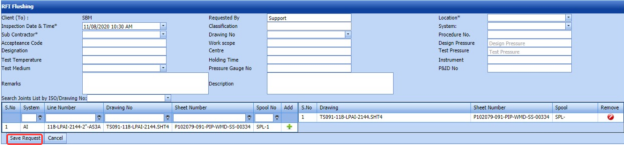


The flushing inspection request will be added and listed in the RFI Flushing Report page.
5.48 View RFI Flushing
The View RFI Flushing tab helps you to view and edit the flushing inspection request, which is added by using the RFI Flushing tab. This tab also allows you to add a new flushing inspection request.
- Click View RFI Flushing in the Inspection menu.
The RFI Flushing Report page opens with a list of added flushing inspection requests.
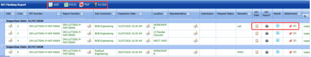
Figure 5.48: RFI Flushing Report page

5.48.1 Add a Flushing Inspection Request
If you want to add a flushing inspection request, do the following steps,
-
Click
 (ADD button) in the RFI Flushing Report page.
The system redirects you to a new page to add a new flushing inspection request. To know how to add a flushing inspection request, See the topic, “Add a Flushing Inspection Request”.

Once you have added the flushing inspection request, you must submit the added request to perform the flushing inspection.
5.48.2 Add Representative for a Flushing Inspection Request
If you want to add a representative for any added flushing inspection request,
- Click
 (Edit icon) in the Representative column for the respective flushing inspection request.
The Edit Form window opens.
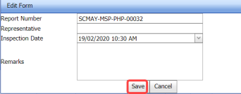
- In the Representative box, enter the name of a representative.
- In the Inspection Date box, select the date of inspection.
- In the Remarks box, enter your remarks if any.
-
Click Save.


5.48.3 Edit a Flushing Inspection Request
If you want to edit any existing flushing inspection request in the RFI Flushing Report page, do the following,
- Click
 (Edit icon) in the Edit column for the respective flushing inspection See Fig 5.48.
The RFI Flushing Report page opens with the details of the selected flushing inspection request.
-
Click any box where you want to edit the details, and then edit the details in the respective box.
-
Click Save.

5.48.4 Submit and Approve a Flushing Inspection Request
Once you have added the flushing inspection request, the Submission column in the RFI Flushing Report page is appeared with  (Submit and Reject icons).
- If you want to submit the flushing inspection request, click
 (Submit icon) in the Submission Otherwise click
  (Reject icon) to reject the request.
Once you have submitted the flushing inspection request, the Request Status column in the RFI Flushing Report page is appeared with
 (Approve and Reject icons).
 - If you want to approve the flushing inspection request, click
 (Approve icon) in the Request Status Otherwise click
 (Reject icon) to reject the request.


The flushing inspection request will be moved for flushing inspection.
5.48.5 Add RFI Data for a Flushing Inspection Request
If you want to add RFI data for the added flushing inspection request, do the following,
- Click
 (Edit icon) in the RFI Data column of the RFI Flushing Report See Fig 5.48.
The RFI Inspection Request List window opens.

- In the Inspection From box, enter the detail from where the inspection should start.
-
In the Inspection To box, enter the detail to where the inspection should end.
- In the Inspection Details option, select 1stInspection, 2nd Inspection or 3rd Inspection according to the inspection details.
- In the Others box, enter any other inspection related details.
- In the Refer to Report No box, enter the report number for reference.
- In the RFI Date box, choose the RFI date.
-
In the Inspection Result option, if the inspection result is accepted, select Accepted otherwise select Rejected.
- In the Remarks box, enter your remarks if any.
- In the Inspected by box, enter the name of a person who has done inspection.
- In the Inspected Date box, choose the date of inspection.
- In the Witnessed By box, enter the name of the witnessed person.
- In the Witnessed Date box, choose the date of witnessed.
- In the PCML Rep Name box, enter the representative name of PCML.
- In the PCML Rep Date box, choose the PCML rep date.
- In the MEB Rep Name box, enter the representative name of MEB.
- In the MEB Rep Date box, choose MEB rep date.
- Click Save.


The RFI data is successfully added.
5.48.6 View an RFI Report
If you want to view an RFI report, click  (print icon) provided in the RFI Report column of the RFI Flushing Report page. See Fig 5.48.
5.48.7 Add Results of Flushing Inspection
After completing the flushing inspection for the added request, you can add the inspection result details. To add results, do the following steps,
-
Click
 (Add icon) in the Results column of the respective request.
The Result window opens a list of spools added for the particular request.

-
In the Result column, select the result of each spool from the given result options in the drop-down list.
- In the Temperature column, enter the temperature value of each spool.
- In the Start Time and End Time columns, enter the start and end times.
-
Click Save.


5.48.8 Attach a File into a Flushing Inspection Request
If you want to attach a file with any existing flushing inspection request listed in the RFI Flushing Report page, you can attach the file by using  (Attach icon) in the Attachment column. To know how to attach, follow the procedures given in the topic “Attach a file into P&ID”.
5.48.9 Export Flushing Inspection Request List
You can export a list of flushing inspection requests added in the RFI Flushing Report page in both the pdf and excel formats by using  (PDF button) and
  (Excel button). To know how to export, see the topic, “Export P&ID list”.
5.48.10 Filter a Flushing Inspection Request
If you want to filter any specific flushing inspection request in the RFI Flushing Report page, you can use  (FILTER button) located on the RFI Flushing Report page. To know how to filter, see the topic, “Filter P&ID”.
5.49 RFI Chemical Cleaning
The RFI Chemical Cleaning tab in the Inspection menu is used to add a request for the pipe chemical cleaning inspection.
5.49.1 Add a Chemical Cleaning Inspection Request
If you want to add a chemical cleaning inspection request, do the following steps,
- Click RFI Chemical Cleaning in the Inspection menu.
The RFI Chemical Cleaning page opens.

Figure 5.49: RFI Chemical Cleaning page
- In the Requested By box, enter the name of a person who has requested the chemical cleaning inspection.
- In the Location box, select the location where the inspection to be performed.
-
In the Inspection Date & Time box, select the inspection date and time.
-
In the Classification box, enter the classification detail.
-
In the System box, select a system from a drop-down list.
-
In the Sub Contractor box, select a sub-contractor from a drop-down list.
-
In the Acceptance Code box, enter the acceptance code detail.
-
In the Designation box, enter the designation detail.
-
In the Test Temperature box, enter the test temperature value.
-
In the Test Medium box, select the test medium from the drop-down list.
-
In the Drawing No box, select the drawing number from a drop-down list.
-
In the Work Scope box, enter the work scope detail.
-
In the Cost Centre box, enter the cost centre detail.
-
In the Holding Time box, enter the holding time range.
-
In the Pressure Gauge No box, enter the pressure gauge number.
-
In the Procedure No box, enter the procedure number.
-
In the Design Pressure box, enter the design pressure range.
-
In the Test Pressure box, enter the test pressure range.
-
In the Instrument box, enter the instrument name.
-
In the P&ID No box, enter the P&ID number.
-
In the Remarks box, enter your remarks if any.
- In the Description box, enter the description for the chemical cleaning inspection.
Before saving the added chemical cleaning inspection request, you must add spools.
 Note: You can add multiple spools for one request.
The RFI Chemical Cleaning page shows a list of added spools. If you want to view the spools for the specific ISO drawing, select the respective ISO drawing from a drop-down list.

- Click
 (Add icon) of the respective spool which you want to add.
The added spools will be moved to the right side of the page.
-
Click Save Request.
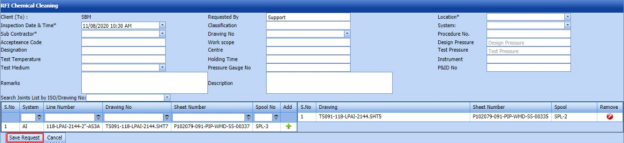


The chemical cleaning inspection request will be added and listed in the RFI Chemical Cleaning Report page.
5.50 View RFI Chemical Cleaning
The View RFI Chemical Cleaning tab helps you to view and edit the chemical cleaning inspection request, which is added by using the RFI Chemical Cleaning tab. This tab also allows you to add a new chemical cleaning inspection request.
- Click View RFI Chemical Cleaning in the Inspection menu.
The RFI Chemical Cleaning Report page opens with a list of added chemical cleaning inspection requests.

Figure 5.50: RFI Chemical Cleaning Report page
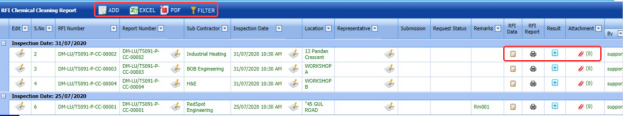
5.50.1 Add a Chemical Cleaning Inspection Request
If you want to add a chemical cleaning inspection request, do the following steps,
- Click
 (ADD button) in the RFI Chemical Cleaning Report page.
The system redirects you to a new page to add a new chemical cleaning inspection request. To know how to add a chemical cleaning inspection request, See the topic, “Add a Chemical Cleaning Inspection Request”.
Once you have added the chemical cleaning inspection request, you must submit the added request to perform the chemical cleaning inspection.

5.50.2 Add Representative for a Chemical Cleaning Inspection Request
If you want to add a representative for any added chemical cleaning inspection request,
- Click
 (Edit icon) in the Representative column for the respective chemical cleaning inspection request.
The Edit Form window opens.

-
In the Representative box, enter the name of a representative.
-
In the Inspection Date box, select the date of inspection.
-
In the Remarks box, enter your remarks if any.
-
Click Save.

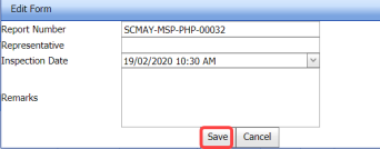
5.50.3 Edit a Chemical Cleaning Inspection Request
If you want to edit any existing chemical cleaning inspection request in the RFI Chemical Cleaning Report page, do the following,
- Click
 (Edit icon) in the Edit column for the respective chemical cleaning inspection See Fig 5.50.
The RFI Chemical Cleaning Report page opens with the details of the selected chemical cleaning inspection request.
-
Click any box where you want to edit the details, and then edit the details in the respective box.
-
Click Save.

5.50.4 Submit and Approve a Chemical Cleaning Inspection Request
Once you have added the chemical cleaning inspection request, the Submission column in the RFI Chemical Cleaning Report page is appeared with  (Submit and Reject icons).
- If you want to submit the chemical cleaning inspection request, click
 (Submit icon) in the Submission Otherwise click
  (Reject icon) to reject the request.
Once you have submitted the chemical cleaning inspection request, the Request Status column in the RFI Chemical Cleaning Report page is appeared with
 (Approve and Reject icons).
 - If you want to approve the chemical cleaning inspection request, click
 (Approve icon) in the Request Status Otherwise click
  (Reject icon) to reject the request.
The chemical cleaning inspection request will be moved for chemical cleaning inspection.


5.50.5 Add RFI Data for a Chemical Cleaning Inspection Request
If you want to add RFI data for the added chemical cleaning inspection request, do the following,
- Click
 (Edit icon) in the RFI Data column of the RFI Chemical Cleaning Report See Fig 5.50.
The RFI Inspection Request List window opens.

-
In the Inspection From box, enter the detail from where the inspection should start.
-
In the Inspection To box, enter the detail to where the inspection should end.
- In the Inspection Details option, select 1stInspection, 2nd Inspection or 3rd Inspection according to the inspection details.
- In the Others box, enter any other inspection related details.
- In the Refer to Report No box, enter the report number for reference.
- In the RFI Date box, choose the RFI date.
-
In the Inspection Result option, if the inspection result is accepted, select Accepted otherwise select Rejected.
- In the Remarks box, enter your remarks if any.
- In the Inspected by box, enter the name of a person who has done inspection.
- In the Inspected Date box, choose the date of inspection.
- In the Witnessed By box, enter the name of the witnessed person.
-
In the Witnessed Date box, choose the date of witnessed.
-
In the PCML Rep Name box, enter the representative name of PCML.
-
In the PCML Rep Date box, choose the PCML rep date.
-
In the MEB Rep Name box, enter the representative name of MEB.
-
In the MEB Rep Date box, choose MEB rep date.
-
Click Save.


The RFI data is successfully added.
5.50.6 View an RFI Report
If you want to view an RFI report, click (print icon) provided in the RFI Report column of the RFI Chemical Cleaning Report page. See Fig 5.50.
5.50.7 Add Results of Chemical Cleaning Inspection
After completing the chemical cleaning inspection for the added request, you can add the inspection result details. To add results, do the following steps,
- Click
 (Add icon) in the Results column of the respective request.
The Result window opens a list of spools added for the particular request.
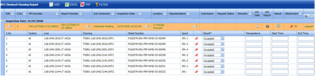
-
In the Result column, select the result of each spool from the given result options in the drop-down list.
-
In the Temperature column, enter the temperature value of each spool.
-
In the Start Time and End Time columns, enter the start and end times.
-
Click Save.


5.50.8 Attach a File into a Chemical Cleaning Inspection Request
If you want to attach a file with any existing chemical cleaning inspection request listed in the RFI Chemical Cleaning Report page, you can attach the file by using  (Attach icon) in the Attachment column. To know how to attach, follow the procedures given in the topic “Attach a file into P&ID”.
5.50.9 Export Chemical Cleaning Inspection Request List
You can export a list of chemical cleaning inspection requests added in the RFI Chemical Cleaning Report page in both the pdf and excel formats by using  (PDF button) and
  (Excel button). To know how to export, see the topic, “Export P&ID list”.
5.50.10 Filter a Chemical Cleaning Inspection Request
If you want to filter any specific chemical cleaning inspection request in the RFI Chemical Cleaning Report page, you can use  (FILTER button) located on the RFI Chemical Cleaning Report page. To know how to filter, see the topic, “Filter P&ID”.
5.51 RFI Reinstatement
The RFI Reinstatement tab in the Inspection menu is used to add a request for pipe reinstatement inspection.
5.51.1 Add a Reinstatement Inspection Request
If you want to add a reinstatement inspection request, do the following steps,
- Click RFI Reinstatement in the Inspection menu.
The RFI Reinstatement page opens.

Figure 5.51: RFI Reinstatement page
- In the Requested By box, enter the name of a person who has requested the reinstatement inspection.
- In the Location box, select the location where the inspection to be performed.
-
In the Inspection Date & Time box, select the inspection date and time.
-
In the Classification box, enter the classification detail.
-
In the System box, select a system from a drop-down list.
-
In the Sub Contractor box, select a sub-contractor from a drop-down list.
-
In the Acceptance Code box, enter the acceptance code detail.
-
In the Designation box, enter the designation detail.
-
In the Test Temperature box, enter the test temperature value.
-
In the Test Medium box, select the test medium from the drop-down list.
-
In the Drawing No box, select the drawing number from a drop-down list.
-
In the Work Scope box, enter the work scope detail.
-
In the Cost Centre box, enter the cost centre detail.
-
In the Holding Time box, enter the holding time range.
-
In the Pressure Gauge No box, enter the pressure gauge number.
-
In the Procedure No box, enter the procedure number.
-
In the Design Pressure box, enter the design pressure range.
-
In the Test Pressure box, enter the test pressure range.
-
In the Instrument box, enter the instrument name.
-
In the P&ID No box, enter the P&ID number.
-
In the Remarks box, enter your remarks if any.
-
In the Description box, enter the description for the reinstatement inspection.
Before saving the added reinstatement inspection request, you must add spools.
 Note: You can add multiple spools for one request.
The RFI Reinstatement page shows a list of added spools. If you want to view the spools for the specific ISO drawing, select the respective ISO drawing from a drop-down list.

- Click
 (Add icon) of the respective spool which you want to add.
The added spools will be moved to the right side of the page.
-
Click Save Request.
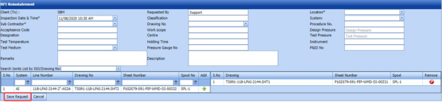


The reinstatement inspection request will be added and listed in the RFI Reinstatement Report page.
5.52 View RFI Reinstatement
The View RFI Reinstatement tab helps you to view and edit the reinstatement inspection request, which is added by using the RFI Reinstatement tab. This tab also allows you to add a new reinstatement inspection request.
-
Click View RFI Reinstatement in the Inspection menu.
The RFI Reinstatement Report page opens with a list of added reinstatement inspection requests.
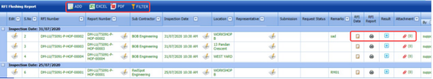
Figure 5.52: RFI Reinstatement Report page

5.52.1 Add a Reinstatement Inspection Request
If you want to add a reinstatement inspection request, do the following steps,
Once you have added the reinstatement inspection request, you must submit the added request to perform the reinstatement inspection.
5.52.2 Add Representative for a Reinstatement Inspection Request
If you want to add a representative for any added reinstatement inspection request,
- Click
 (Edit icon) in the Representative column for the respective reinstatement inspection request.
The Edit Form window opens.

-
In the Representative box, enter the name of a representative.
-
In the Inspection Date box, select the date of inspection.
-
In the Remarks box, enter your remarks if any.
-
Click Save.


5.52.3 Edit a Reinstatement Inspection Request
If you want to edit any existing reinstatement inspection request in the RFI Reinstatement Report page, do the following,
- Click
 (Edit icon) in the Edit column for the respective reinstatement inspection See Fig 5.52.
The RFI Reinstatement Report page opens with the details of the selected reinstatement inspection request.
- Click any box where you want to edit the details, and then edit the details in the respective box.
- Click Save.

5.52.4 Submit and Approve a Reinstatement Inspection Request
Once you have added the reinstatement inspection request, the Submission column in the RFI Reinstatement Report page is appeared with  (Submit and Reject icons).
- If you want to submit the reinstatement inspection request, click
 (Submit icon) in the Submission Otherwise click
  (Reject icon) to reject the request.
Once you have submitted the reinstatement inspection request, the Request Status column in the RFI Reinstatement Report page is appeared with
 (Approve and Reject icons).
 - If you want to approve the reinstatement inspection request, click
 (Approve icon) in the Request Status Otherwise click
  (Reject icon) to reject the request.
The reinstatement inspection request will be moved for reinstatement inspection.


5.52.5 Add RFI Data for a Reinstatement Inspection Request
If you want to add RFI data for the added reinstatement inspection request, do the following,
- Click
 (Edit icon) in the RFI Data column of the RFI Reinstatement Report See Fig 5.52.
The RFI Inspection Request List window opens.

-
In the Inspection From box, enter the detail from where the inspection should start.
-
In the Inspection To box, enter the detail to where the inspection should end.
- In the Inspection Details option, select 1stInspection, 2nd Inspection or 3rd Inspection according to the inspection details.
-
In the Others box, enter any other inspection related details.
-
In the Refer to Report No box, enter the report number for reference.
-
In the RFI Date box, choose the RFI date.
- In the Inspection Result option, if the inspection result is accepted, select Accepted otherwise select Rejected.
-
In the Remarks box, enter your remarks if any.
-
In the Inspected by box, enter the name of a person who has done inspection.
-
In the Inspected Date box, choose the date of inspection.
-
In the Witnessed By box, enter the name of the witnessed person.
-
In the Witnessed Date box, choose the date of witnessed.
-
In the PCML Rep Name box, enter the representative name of PCML.
-
In the PCML Rep Date box, choose the PCML rep date.
-
In the MEB Rep Name box, enter the representative name of MEB.
-
In the MEB Rep Date box, choose MEB rep date.
-
Click Save.


The RFI data is successfully added.
5.52.6 View an RFI Report
If you want to view an RFI report, click  (print icon) provided in the RFI Report column of the RFI Reinstatement Report page. See Fig 5.52.
5.52.7 Add Results of Reinstatement Inspection
After completing the reinstatement inspection for the added request, you can add the inspection result details. To add results, do the following steps,
- Click
 (Add icon) in the Results column of the respective request.
The Result window opens a list of spools added for the particular request.

- In the Result column, select the result of each spool from the given result options in the drop-down list.
- In the Temperature column, enter the temperature value of each spool.
-
In the Start Time and End Time columns, enter the start and end times.
-
Click Save.

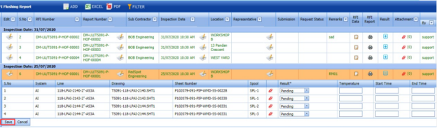
5.52.8 Attach a File into a Reinstatement Inspection Request
If you want to attach a file with any existing reinstatement inspection request listed in the RFI Reinstatement Report page, you can attach the file by using  (Attach icon) in the Attachment column. To know how to attach, follow the procedures given in the topic “Attach a file into P&ID”.
5.52.9 Export Reinstatement Inspection Request List
You can export a list of reinstatement inspection requests added in the RFI Reinstatement Report page in both the pdf and excel formats by using  (PDF button) and
  (Excel button). To know how to export, see the topic, “Export P&ID list”.
5.52.10 Filter a Reinstatement Inspection Request
If you want to filter any specific reinstatement inspection request in the RFI Reinstatement Report page, you can use  (FILTER button) located on the RFI Reinstatement Report page. To know how to filter, see the topic, “Filter P&ID”.
5.53 Inspection Requisition Summary Report
The Inspection Requisition Summary tab in the Inspection menu used to view the inspection requisition summary report for a particular period.
- Click Inspection Requisition Summary in the Inspection menu.
The Requisition Inspection Summary page opens.
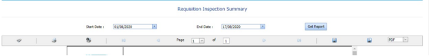
Figure 5.53: Requisition Inspection Summary page
-
In the Start Date and End Date boxes, select the start and end dates.
-
Click Get Report.
The inspection requisition summary report for the selected period will be opened.
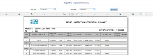


5.53.1 Print an Inspection Requisition Summary Report
If you want to print an inspection requisition summary report, use and
and  (print icons) provided in the Requisition Inspection Summary page.
- If you want to print the current page of the inspection requisition summary report, click
 (print icon including the page number).
 -
If you want to print all the pages of the inspection requisition summary report, click
 (print icon).


5.53.2 Export an Inspection Requisition Summary Report
You can export the inspection requisition summary report in various formats by using the option  provided in the upper right corner of the Requisition Inspection Summary page.
Piping
6.0 Piping
6.1 Radiographic Testing (RT)
RT inspection method is one of the types of NDT inspection used to conduct inspection in the piping project by using either x-rays or gamma rays.
Once the NDT inspection request is added with the selection of RT type by using the NDT Inspection Request tab, the added inspection request will be moved here. After completing RT inspection, you can add the RT inspection result details by using this RT tab.
-
Click Radiographic Testing (RT) in the Piping menu.
The RT Report page opens.

Figure 6.1: RT Report page
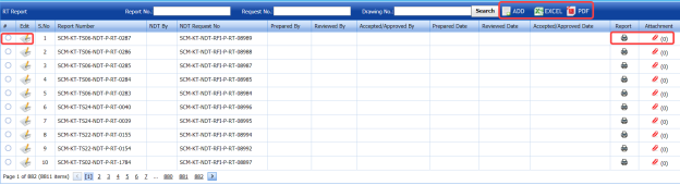
6.11 Add an RT Report
If you want to add an RT report, do the following steps,
-
Click (ADD button) in the RT Report page. See Fig 6.1.
The RT Report page opens a new window to add an RT report.

 Note: The fields notified with a symbol (*) are mandatory. You must enter the relevant details in that fields before saving.
 Tip: A report number for a new RT report will be updated automatically in the Report Number box. If you want change the report number, you can change.
 - In the NDT By box, select the requisition detail of NDT whether by third party or internal from a drop-down list.
- In the NDT Request No box, select an RT request number from a drop-down list.
- In the Prepared By box, enter the name of a person who has prepared the RT report.
- In the Prepared Date box, select the prepared date of the RT report.
- In the Reviewed By box, enter the name of a person who has reviewed the RT report.
- In the Reviewed Date box, select the reviewed date of the RT report.
-
In the Accepted/Approved By boxes, enter the name of a person who has accepted/approved the RT report.
- In the Accepted/Approved Date box, select the accepted/approved date of the RT report.
-
Click Save.
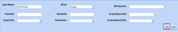


The RT report is successfully added. Once you have added the RT report, you must add RT inspection results.
6.1.2 Add RT Inspection Results
If you want to add the RT inspection results for the added RT report, do the following steps,
- Click the respective added RT report in the RT Report See Fig 6.1.
The RT Report page shows RT Results, Joint Results, and Report Photos windows to add RT results.
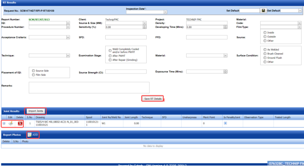
Figure 6.1.1: RT Results page
- In the Inspection Date box, select the date of inspection.
- In the Image Quality Indicator (IQI) box, select IQI from a drop-down list.
- In the Source & Size (MM) box, select the RT source and their size from a drop-down list.
- In the Density box, enter the radiographic density range.
- In the Code box, select the code of the material from a drop-down list.
- In the Procedure Number box, select the procedure number from a drop-down list.
- In the Sensitivity (%)box, set the radiographic sensitivity by using up and down arrows.
- In the Developing Time (Mins)box, set the developing time by using up and down arrows.
- In the Film/ Type box, select the name of a film including type from a drop-down list.
- In the Acceptance Criteria box, select the acceptance criteria from a drop-down list.
-
In the Source to Film Distance (SFD) box, enter the distance range between the source and the film.
- In the Focus Film Distance (FFD)box, enter the focus film distance range.
- In the Source box, select any one source option whether inside, outside, or other.
- In the Technique box, select the radiographic technique from a drop-down list.
- In the Examination Stage box, select the examination stage from the specified options.
- In the Material box, select the material from a drop-down list.
- In the Surface Condition box, select the condition of the surface from the specified options.
- In the Placement of IQI box, select any one option from source side and film side.
- In the Source Strength (Ci)box, enter the source strength value.
- In the Exposure Time (Mins)box, set the exposure time by using up and down arrows.
- In the Remarks box, enter your remarks if any.
-
Click Save RT Details.
The RT details are successfully updated. Once you have updated the RT details, you must add marker results of added joints.

 Note: Once you have added RT details, you can save the added RT details and reuse the saved details while you adding RT details for any other RT report.

- To save the added RT details, enter any name in the Set Default box and click .
-
If you want to add the same RT details for any other RT report, select the name in the Get Default.
The saved details will be automatically updated in the respective boxes.
6.1.2.1 Add Marker Results for Joints
The RT Results window shows a list of joints added for the RT inspection. If you want to add marker results for the respective joints,
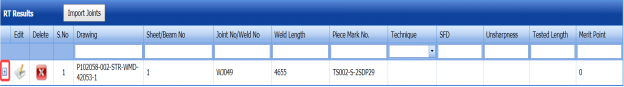
- Click
 (Add icon) for the respective joint.
The Marker Results window opens with a list of markers of the respective joint.
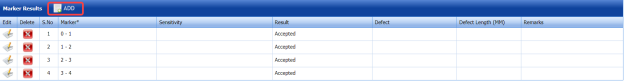
- If you want to add any additional markers, click
 (ADD button).
The Marker Results window shows a new window to add a new marker.

-
-
In the Marker box, enter the marker number.
- In the Sensitivity box, enter the sensitivity range.
- In the Result box, select the marker result from the given result options.
- In the Defect box, select the defect type if any.
- In the Defect Length (MM)box, enter the defect length value.
- In the Remarks box, enter your remarks if any.
-
Click Save. The marker is added and listed in the Marker Results window.
-
-
-
If you want to update marker results,
-
- Click
 (Edit icon) in the Edit column for the respective marker results.
A new window opens to edit the marker results.
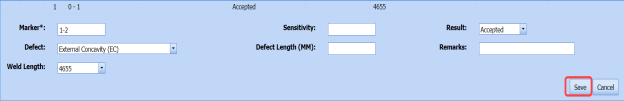
-
Click any box where you want to edit the details, and edit the marker results.
-
Click Save.
- Click
-
- If you want delete any existing marker results, click
 (Delete icon) for the respective marker results.


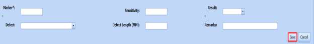


9.1.2.2 Import Additional Joints
If you want to import additional joints for the RT inspection,
- Click
 (Import Joints button) in the RT Results See Fig 6.1.1.
The Joints window opens with a list of joints.

-
Select the joints you want to import.
- Click
 (Import Selected Joints button).
The selected joints are imported for the respective RT inspection. Once you have imported the joints, you must perform the RT inspection and add the marker results for the added joints.


6.1.2.3 Add Report Photos
If you want to add any report photos for the updated RT results,
- Click
 (ADD button) in the Report Photos box in the RT Results See Fig 6.1.1.

- Click
 (Browse button) to browse a photo stored in your computer.
 -
Click Upload.
The selected photo will be updated.


6.1.3 Attach a File into an RT Report
If you want to attach any file with any RT report listed in the RT Report page, you can attach the file by using (Attach icon) in the Attachment column. To know how to attach, follow the procedures given in the topic “Attach a file into P&ID”.
6.1.4 View an NDT – RT Report
If you want to view an NDT - RT report, click (print icon) provided in the Report column of the RT Report page. See Fig 6.1.
6.1.5 Edit an RT Report
If you want to edit any existing RT report in the RT Report page, do the following,
- Click
 (Edit icon) in the Edit column for the respective RT report. See Fig 6.1.
A new window opens to edit the RT report.

-
Click any box where you want to edit the details, and then edit the details in the respective box.
-
Click Save.
-
If you want to edit the RT inspection results of any report, click the respective report and change the results.


6.1.6 Export RT Report List
You can export a list of RT reports added in the RT Report page in both the pdf and excel formats by using  (PDF button) and
  (Excel button). To know how to export, see the topic, “Export P&ID list”.
6.1.7 Filter an RT Report
If you want to filter any RT report, do one of the following,

-
If you want to filter any RT report based on the report number, enter the corresponding report number in the Report No box in the RT Report page, and then Click Search.
- If you want to filter any RT report based on the request number, enter the corresponding request number in the Request No box in the RT Report page, and then Click Search.
- If you want to filter any RT report based on the drawing number, enter the corresponding drawing number in the Drawing No box in the RT Report page, and then Click Search.
6.2 Ultrasonic Testing (UT)
The UT method is one of the NDT inspection methods used for performing inspection in the piping project by using high frequency sound waves.
Once the NDT inspection request is added with the selection of UT type by using the NDT Inspection Request tab, the added inspection request will be moved here. After completing UT inspection, you can add the UT inspection result details by using this UT tab.
-
Click the Ultrasonic Testing (UT) tab in the Piping menu.
The UT Report page opens.
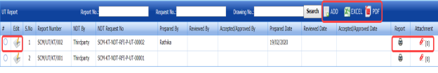
Figure 6.2: UT Report page

6.2.1 Add an UT Report
If you want to add an UT report, do the following,
-
Click
 (ADD button) in the UT Report page. See Fig 6.2.
A new window opens to add an UT report.

 Note: The fields notified with a symbol (*) are mandatory. You must enter the relevant details in that fields before saving.
 Tip: A report number for a new UT report will be updated automatically in the Report Number box.
 - In the NDT By box, select the requisition of NDT whether by third party or internal from a drop-down list.
-
In the NDT Request No box, select an UT request number from a drop-down list.
- In the Prepared By box, enter the name of a person who has prepared the UT report.
- In the Prepared Date box, select the prepared date of the UT report.
- In the Reviewed By box, enter the name of a person who has reviewed the UT report.
- In the Reviewed Date box, select the reviewed date of the UT report.
-
In the Accepted/Approved By boxes, enter the name of a person who has accepted/approved the UT report.
- In the Accepted/Approved Date box, select the accepted/approved date of the UT report.
- In the Accept Date box, select the report accept date.
- Click Save.


The UT report is successfully added. Once you have added the UT report, you must add UT results for the respective added UT report.
6.2.2 Add UT Results
If you want to add the UT results for the respective UT report, do the following,
-
Click the respective added UT report in the UT Report page. See Fig 6.2.
The UT Report page shows UT Results, Probe & Cable Details, Reference Setting Details, UT Results, and Report Photos windows.
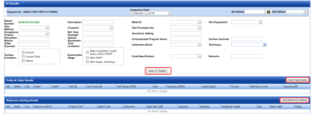
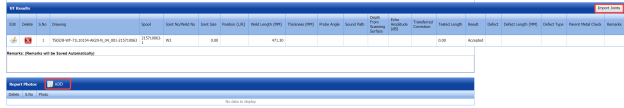
Figure 6.2.1: UT Results page
-
In the Inspection Date box, select the date of UT inspection.
-
In the Test Method box, select the test method from a drop-down list.
-
In the Description box, enter the description about the UT inspection.
-
In the Material box, select the material from a drop-down list.
-
In the Test Equipment box, select the test equipment from a drop-down list.
-
In the Acceptance Criteria box, select the acceptance criteria from a drop-down list.
-
In the Couplant box, select the couplant material from a drop-down list.
-
In the Test Procedure No box, select the test procedure number from a drop-down list.
-
In the Simulation Blocks box, enter the detail of simulation blocks.
-
In the Ref. Hole Diameter box, enter the diameter value of the reference hole.
-
In the Sensitivity Setting box, enter the information about the sensitivity setting.
-
In the Sides Scanned box, enter the details of the sides that are scanned.
-
In the Special Equipment box, enter the name of the special equipment if any.
-
In the Computerized Program Name box, enter the computerized program name.
-
In the Surface Scanned box, the details of the surfaces that are scanned.
-
In the Scan Limitation box, enter the limitation range of scanning.
-
In the Code/Specification box, select the specification from a drop-down list.
-
In the Calibration Block box, select the calibration block from a drop-down list.
-
In the Technique box, select the technique from a drop-down list.
-
In the Examination Stage box, select the examination stage from the specified options.
-
In the Surface Condition box, select the surface condition from the specified options.
-
In the Remarks box, enter your remarks if any.
-
Click Save UT Details.


The UT details are successfully updated. Once you have updated the UT details, you must add the probe and cable details for the UT inspection.
 Note: Once you have added UT details, you can save the added UT details and reuse the saved details while you adding UT details for any other UT report.

- To save the added UT details, enter any name in the Set Default box and click
 .
.
The added details will be saved in the given name.
-
If you want to add the same UT details for any other UT report, select the name in the Get Default.

The saved details will be automatically updated in the respective boxes.
6.2.2.1 Add Probe & Cable Details
If you want to add probe and cable details for the updated UT results,
- Click (Add Probe/ Cable button) in the Probe& Cable Details See Fig 6.2.1.
A new window opens to add the probe and cable details.

- In the Probe box, select a probe from a drop-down list.
- In the Cable box, select a cable from a drop-down list.
- In the dB box, enter the reference decibel range.
- In the Surf Comp dB box, enter the decibel range of the surface component.
- In the Test Range (MM) box, enter the test range in millimeters.
- In the Reference Level box, enter the reference level detail.
- In the Scanning dB box, enter the scanning decibel range.
- In the TR Loss box, enter the transmission loss detail.
- Click Save.

The probe and cable details are successfully added. Once you have added the probe and cable details, you must add the reference setting details.
6.2.2.2 Add Reference Setting Details
If you want to add the reference setting details for the updated UT results,
-
Click
 (Add Reference Setting button) in the Reference Setting Details window. See Fig 6.2.1.
A new window opens to add the reference setting details.

-
In the Reference Block box, select the reference block from a drop-down list.
-
In the Probe Sr. No box, select the serial number of the probe from a drop-down list.
-
In the Reference box, enter the reference detail.
-
In the Eqpt Gain (dB) box, enter the equipment gain in decibels.
-
In the Damping box, enter the damping ratio.
- In the Rejection box, enter the rejection detail.
- In the Amplitude Height box, enter the amplitude height range.
- In the Skip box, enter the skip detail.
- In the Beam Path box, enter the beam path detail.
-
In the Range box, enter the range detail.
-
Click Save.

The reference setting details are successfully added. Once you have added the reference setting details, you must add the inspection results for added joints.
6.2.2.3 Add UT Results
The UT Results window shows a list of joints added for the UT inspection. If you want to add UT results for joints,
-
Click
 (Edit icon) for the respective UT results listed in the UT Results window.
The UT Results window opens with the added UT details.

- In the Result box, update your UT inspection results whether Accepted, Rejected, or Cancelled.
- In the Remarks box, enter your remarks if any.
-
Click Save.


6.2.2.4 Import Additional Joints
If you want to add more joints, you can add by using the import joints option. To import joints,
- Click
 (Import Joints button) in the UT Results See Fig 6.2.1.
The Joints window opens with a list of joints.

- Select the joints you want to import.
- Click
 (Import Selected Joints button).

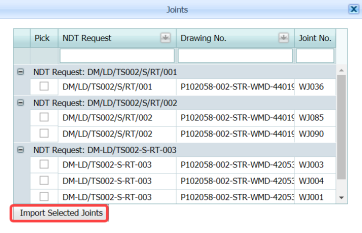

The selected joints are imported for the respective UT and listed in the UT Results window. Once you have imported the joints, you must add the UT results for the imported joints.
6.2.2.5 Add Report Photos
If you want to add any report photos for the updated UT results,
- Click
 (ADD button) in the Report Photos box in the UT Results See Fig 6.2.1.

- Click
 (Browse button) to browse a photo stored in your computer.
 -
Click Upload.
The selected photo will be updated.


The UT results will be updated successfully.
6.2.3 Attach a File into an UT Report
If you want to attach any file with any UT report listed in the UT Report page, you can attach the file by using  (Attach icon) in the Attachment column. To know how to attach, follow the procedures given in the topic “Attach a file into P&ID”.
6.2.4 View an NDT – UT Report
If you want to print an NDT - UT report, click  (print icon) provided in the Report column of the UT Report page. See Fig 6.2.
6.2.5 Edit an UT Report
If you want to edit any existing UT report in the UT Report page, do the following,
- Click
 (Edit icon) in the Edit column for the respective UT report. See Fig 6.2.
A new window opens to edit the UT report.

-
Click any box where you want to edit the details, and then edit the details in the respective box.
- Click Save.

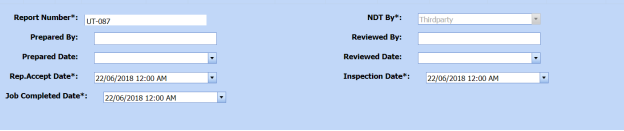
6.2.6 Export UT Report List
You can export a list of UT reports added in the UT Report page in both the pdf and excel formats by using  (PDF button) and
  (Excel button). To know how to export, see the topic, “Export P&ID list”.
6.2.7 Filter an UT Report
If you want to filter any UT report, do one of the following,

- If you want to filter any UT report based on the report number, enter the corresponding report number in the Report No box in the UT Report page, and then Click Search.
-
If you want to filter any UT report based on the request number, enter the corresponding request number in the Request No box in the UT Report page, and then Click Search.
- If you want to filter any UT report based on the drawing number, enter the corresponding drawing number in the Drawing No box in the UT Report page, and then Click Search.
6.3 Ultrasonic Thickness Testing (UTG)
The UTG method is one of the NDT inspection methods used for performing inspection in the piping project.
Once the NDT inspection request is added with the selection of UTG type by using the NDT Inspection Request tab, the added inspection request will be moved here. After completing UTG inspection, you can add the UTG inspection result details by using this UTG tab.
- Click the Ultrasonic Testing (UTG) tab in the Piping menu.
The UTG Report page opens.

Figure 6.3: UTG Report page

6.3.1 Add an UTG Report
If you want to add an UTG report, do the following,
-
Click
 (ADD button) in the UTG Report page. See Fig 6.3.
A new window opens to add an UTG report.

 Note: The fields notified with a symbol (*) are mandatory. You must enter the relevant details in that fields before saving.
 Tip: A report number for a new UTG report will be updated automatically in the Report Number box.
 -
In the NDT By box, select the requisition of NDT whether by third party or internal from a drop-down list.
- In the NDT Request No box, select an UTG request number from a drop-down list.
- In the Prepared By box, enter the name of a person who has prepared the UTG report.
- In the Prepared Date box, select the prepared date of the UTG report.
- In the Reviewed By box, enter the name of a person who has reviewed the UTG report.
- In the Reviewed Date box, select the reviewed date of the UTG report.
- In the Accepted/Approved By boxes, enter the name of a person who has accepted/approved the UTG report.
- In the Accepted/Approved Date box, select the accepted/approved date of the UTG report.
- In the Accept Date box, select the report accept date.
-
Click Save.

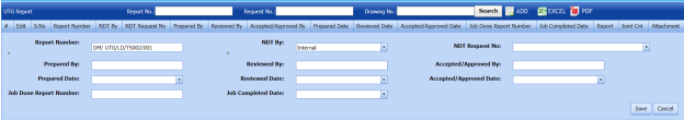


The UTG report is successfully added. Once you have added the UTG report, you must add UTG results for the respective added UTG report.
6.3.2 Add UTG Results
If you want to add the UTG results for the respective UT report, do the following steps,
- Click the respective added UTG report in the UTG Report See Fig 6.3.
The UT Report page shows UTG Details, Probe & Cable Details, Reference Setting Details, UTG Results, and Report Photos windows.
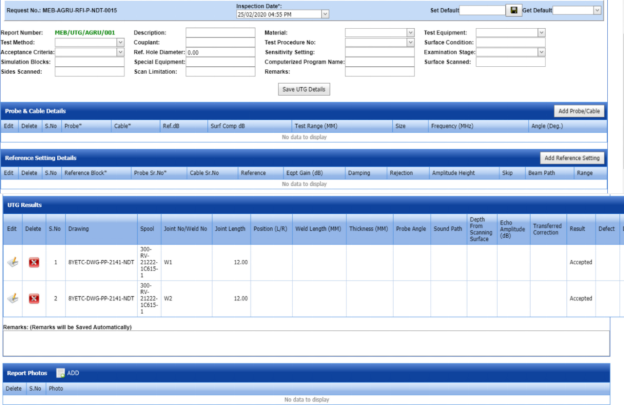
Figure 6.3.1: UTG Results page
- In the Inspection Date box, select the date of UTG inspection.
- In the Test Method box, select the test method from a drop-down list.
- In the Description box, enter the description about the UTG inspection.
- In the Material box, select the material from a drop-down list.
- In the Test Equipment box, select the test equipment from a drop-down list.
- In the Acceptance Criteria box, select the acceptance criteria from a drop-down list.
- In the Couplant box, select the couplant material from a drop-down list.
- In the Test Procedure No box, select the test procedure number from a drop-down list.
- In the Simulation Blocks box, enter the detail of simulation blocks.
- In the Hole Diameter box, enter the diameter value of the reference hole.
- In the Sensitivity Setting box, enter the information about the sensitivity setting.
- In the Sides Scanned box, enter the details of the sides that are scanned.
- In the Special Equipment box, enter the name of the special equipment if any.
-
In the Computerized Program Name box, enter the computerized program name.
- In the Surface Scanned box, the details of the surfaces that are scanned.
- In the Scan Limitation box, enter the limitation range of scanning.
- In the Remarks box, enter your remarks if any.
-
Click Save UTG Details.
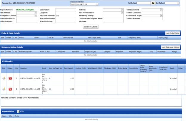
The UTG details are successfully updated. Once you have updated the UTG details, you must add the probe and cable details for the UTG inspection.
 Note: Once you have added UTG details, you can save the added UTG details and reuse the saved details while you adding UTG details for any other UTG report.

- To save the added UTG details, enter any name in the Set Default box and click .
The added details will be saved in the given name.
- If you want to add the same UTG details for any other UTG report, select the name in the Get Default.
The saved details will be automatically updated in the respective boxes.
6.3.2.1 Add Probe & Cable Details
If you want to add probe and cable details for the updated UTG results,
- Click
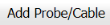 (Add Probe/ Cable button) in the Probe& Cable Details See Fig 6.3.1.
A new window opens to add the probe and cable details.

-
In the Probe box, select a probe from a drop-down list.
-
In the Cable box, select a cable from a drop-down list.
-
In the Ref. dB box, enter the reference decibel range.
-
In the Surf Comp dB box, enter the decibel range of the surface component.
-
In the Test Range (MM) box, enter the test range in millimeters.
-
In the Reference Level box, enter the reference level detail.
-
In the Scanning dB box, enter the scanning decibel range.
-
In the TR Loss box, enter the transmission loss detail.
-
Click Save.

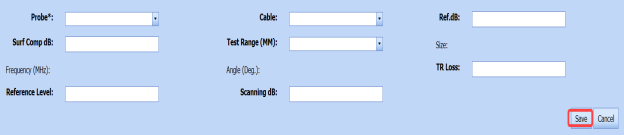
The probe and cable details are successfully added. Once you have added the probe and cable details, you must add the reference setting details.
6.3.22 Add Reference Setting Details
If you want to add the reference setting details for the updated UTG results,
-
Click
 (Add Reference Setting button) in the Reference Setting Details window. See Fig 6.3.1.
A new window opens to add the reference setting details.
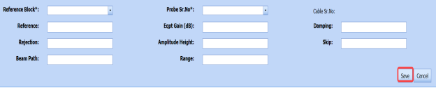
- In the Reference Block box, select the reference block from a drop-down list.
- In the Probe Sr. No box, select the serial number of the probe from a drop-down list.
- In the Reference box, enter the reference detail.
- In the Eqpt Gain (dB) box, enter the equipment gain in decibels.
- In the Damping box, enter the damping ratio.
- In the Rejection box, enter the rejection detail.
- In the Amplitude Height box, enter the amplitude height range.
- In the Skip box, enter the skip detail.
- In the Beam Path box, enter the beam path detail.
-
In the Range box, enter the range detail.
-
Click Save.


The reference setting details are successfully added. Once you have added the reference setting details, you must add the inspection results for added joints.
6.3.2.3 Add UTG Results
The UTG Results window shows a list of joints added for the UTG inspection. If you want to add UTG results for joints,
- Click
 (Edit icon) for the respective UTG results listed in the UTG Results window.
The UTG Results window opens with the added UTG details.
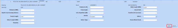
-
In the Result box, update your UTG inspection results whether Accepted, Rejected, or Cancelled.
-
In the Remarks box, enter your remarks if any.
-
Click Save.


6.3.2.4 Import Additional Joints
If you want to add more joints, you can add by using the import joints option. To import joints,
- Click (Import Joints button) in the UTG Results See Fig 6.3.1.
The Joints window opens with a list of joints.

-
Select the joints you want to import.
-
Click
 (Import Selected Joints button).
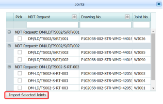

The selected joints are imported for the respective UTG and listed in the UTG Results window. Once you have imported the joints, you must add the UTG results for the imported joints.
6.3.2.5 Add Report Photos
If you want to add any report photos for the updated UTG results,
-
Click (ADD button) in the Report Photos box in the UTG Results window. See Fig 6.3.1.

- Click
 (Browse button) to browse a photo stored in your computer.
 -
Click Upload.
The selected photo will be updated.


The UTG results will be updated successfully.
6.3.3 Attach a File into an UTG Report
If you want to attach any file with any UTG report listed in the UTG Report page, you can attach the file by using  (Attach icon) in the Attachment column. To know how to attach, follow the procedures given in the topic “Attach a file into P&ID”.
6.3.4 View an NDT – UTG Report
If you want to print an NDT - UTG report, click  (print icon) provided in the Report column of the UTG Report page. See Fig 6.3.
6.3.5 Edit an UTG Report
If you want to edit any existing UTG report in the UTG Report page, do the following,
- Click (Edit icon) in the Edit column for the respective UTG report. See Fig 6.3.
A new window opens to edit the UTG report.

- Click any box where you want to edit the details, and then edit the details in the respective box.
-
Click Save.

6.3.6 Export UTG Report List
You can export a list of UTG reports added in the UTG Report page in both the pdf and excel formats by using (PDF button) and
  (Excel button). To know how to export, see the topic, “Export P&ID list”.
6.3.7 Filter an UTG Report
If you want to filter any UTG report, do one of the following,

- If you want to filter any UTG report based on the report number, enter the corresponding report number in the Report No box in the UTG Report page, and then Click Search.
-
If you want to filter any UTG report based on the request number, enter the corresponding request number in the Request No box in the UTG Report page, and then Click Search.
- If you want to filter any UTG report based on the drawing number, enter the corresponding drawing number in the Drawing No box in the UTG Report page, and then Click Search.
6.4 Dye Penetrant Testing (PT)
Dye Penetrant Testing (DPT) method is one of the oldest and simplest NDT inspection methods used for inspecting the materials in the piping project by using ultraviolet or white light, depending on the type of dye used - fluorescent or non fluorescent (visible). PT also called liquid penetrate inspection (LPI) or penetrant testing (PT).
Once the NDT inspection request is added with the selection of PT type by using the NDT Inspection Request tab, the added inspection request will be moved here. After completing PT inspection, you can add the PT inspection result details by using this PT tab.
-
Click Dye Penetrant Testing (PT) in the Piping menu.
The PT Report page opens.

Figure 6.4: PT Report page
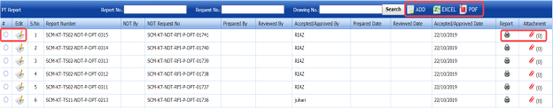
6.4.1 Add a PT Report
If you want to add a PT report, do the following steps,
-
Click
 (ADD button) in the PT Report page. See Fig 6.4.
The PT Report page opens a new window to add an PT report.
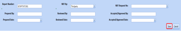
 Note: The fields notified with a symbol (*) are mandatory. You must enter the relevant details in that fields before saving.
 Tip: A report number for a new PT report will be updated automatically in the Report Number box.
 - In the NDT By box, select the requisition detail of NDT whether by third party or internal from a drop-down list.
-
In the NDT Request No box, select an NDT request number from a drop-down list.
-
In the Prepared By box, enter the name of a person who has prepared the PT report.
-
In the Prepared Date box, select the prepared date of the PT report.
-
In the Reviewed By box, enter the name of a person who has reviewed the PT report.
-
In the Reviewed Date box, select the reviewed date of the PT report.
- In the Accepted/Approved By boxes, enter the name of a person who has accepted/approved the PT report.
- In the Accepted/Approved Date box, select the accepted/approved date of the PT report.
-
Click Save.


The PT report is successfully added and listed in the PT Report page. Once you have added the PT report, you must add PT results for the respective added PT report.
6.4.2 Add PT Results
If you want to add the PT results for the respective PT report, do the following steps,
- Click the respective added PT report in the PT Report See Fig 6.4.
The RT Report page shows the DPT Results and Report Photos windows.
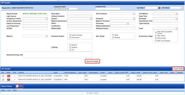
Figure 6.4.1: DPT Results page
- In the Inspection Date box, select the date of DPT inspection.
- In the Inspection By box, enter the name of a person who has done the DPT inspection.
-
In the Light Source box, enter the light source detail.
-
In the Description box, enter the description.
-
In the Test Procedure box, select the test procedure from a drop-down list.
-
In the Test Method box, select the test method from a drop-down list.
-
In the Acceptance Criteria box, select the acceptance criteria from a drop-down list.
-
In the Surface Condition box, enter the condition of the surface.
-
In the Dwell Time box, enter dwell time range.
-
In the Surface Temperature box, enter the surface temperature value.
-
In the Cleaner box, select the cleaner from a drop-down list.
-
In the Penetrant box, select the penetrant from a drop-down list.
-
In the Developer box, select the developer from a drop-down list.
-
In the Material Specification box, enter the material specification.
-
In the Material Thickness box, enter the material thickness value.
-
In the Development Time box, enter the time for development.
-
In the Extend of Scanning box, enter the details of scanning extend.
-
In the PWHT box, enter the PWHT detail.
-
In the Technique box, select the PT technique from a drop-down list.
-
In the Light Intensity box, enter the light intensity value.
-
In the Joint Preparation box, enter the joint preparation detail.
-
In the Certification box, enter the certification detail.
-
In the Reference Standard box, enter the reference standard detail.
-
In the Reference No box, enter the reference number.
-
In the Welding Process box, enter the type of welding process.
-
In the Code box, enter the code detail.
-
In the Examination Stage box, select the examination stage from the specified options.
-
In the Item Tested box, select the tested items from the specified options.
-
In the Inspection Method box, select the inspection method from the specified options.
-
In the Material box, select the material from a drop-down list.
-
In the Penetrant System box, select the type of penetrant system.
-
In the Lighting box, select the type of lighting.
-
In the Remarks/Drawing Title box, enter your remarks if any.
-
Click Save DPT Details.

The DPT details are successfully updated. Once you have updated the DPT details, you must add DPT inspection results for the added joints.
 Note: Once you have added DPT details, you can save the added DPT details and reuse the saved details while you adding DPT details for any other DPT report.

- To save the added DPT details, enter any name in the Set Default box and click .
- If you want to add the same DPT details for any other DPT report, select the name in the Get Default.
The saved details will be automatically updated in the respective boxes.
6.4.2.1 Add PT Results for Joints
The DPT Results window shows a list of joints added for the PT inspection. If you want to add PT results for joints,
- Click
 (Edit icon) for the respective joint listed in the DPT Results window.
The UT Results window opens with the added UT details.
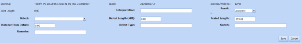
-
In the Result box, update your PT inspection results whether Accepted, Rejected, or Cancelled.
-
In the Remarks box, enter your remarks if any.
-
Click Save.


6.4.2.2 Import Additional Joints
If you want to add more joints, you can add by using the import joints option. To import joints,
-
Click
 (Import Joints button) in the DPT Results window. See Fig 6.4.1.
The Joints window opens with a list of joints.

-
Select the joints you want to import.
- Click
 (Import Selected Joints button).
The selected joints are imported and listed in the DPT Results window. Once you have added joints, you must update the DPT results for added joints.


6.4.2.3 Add Report Photos
If you want to add any report photos for the updated DPT results,
- Click
 (ADD button) in the Report Photos box in the DPT Results See Fig 6.4.1.

-
Click
 (Browse button) to browse a photo stored in your computer.
 -
Click Upload.


The selected photo will be updated.
6.4.3 Attach a File into a PT Report
If you want to attach any file with any PT report listed in the PT Report page, you can attach the file by using  (Attach icon) in the Attachment column. To know how to attach, follow the procedures given in the topic “Attach a file into P&ID”.
6.4.4 View an NDT – PT Report
If you want to view an NDT - PT report, click  (print icon) provided in the Report column of the PT Report page. See Fig 6.4.
6.4.5 Edit a PT Report
If you want to edit any existing PT report in the RT Report page, do the following steps,
- Click
 (Edit icon) in the Edit column for the respective DPT report. See Fig 6.4.
The RT Report page shows the details of the selected PT report.

- Click any box where you want to edit the details, and then edit the details in the respective box.
-
Click Save.

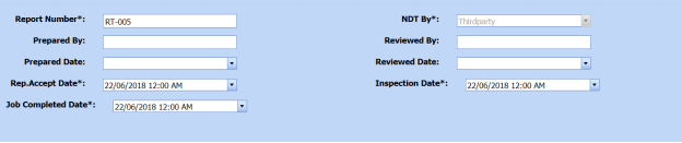
6.4.6 Export PT Report List
You can export a list of RT reports added in the RT Report page in both the pdf and excel formats by using (PDF button) and
  (Excel button). To know how to export, see the topic, “Export P&ID list”.
6.4.7 Filter a PT Report
If you want to filter any PT report, do one of the following,

- If you want to filter any DPT report based on the report number, enter the corresponding report number in the Report No box in the PT Report page, and then Click Search.
- If you want to filter any DPT report based on the request number, enter the corresponding request number in the Request No box in the PT Report page, and then Click Search.
- If you want to filter any DPT report based on the drawing number, enter the corresponding drawing number in the Drawing No box in the PT Report page, and then Click Search.
6.5 Magnetic Particle Testing (MT)
Magnetic Particle Testing also referred to as Magnetic Particle Inspection is one of the NDT inspection methods used to detect defects or discontinuities such as cracks, at or near the surface in ferromagnetic metals such as iron, steel, nickel, cobalt and so on, in the piping project.
Once the NDT inspection request is added with the selection of MT type by using the NDT Inspection Request tab, the added inspection request will be moved here. After completing the MT inspection, you can add the MT inspection result details by using this MT tab.
- Click Magnetic Particle Testing (MT)in the Piping menu.
The MT Report page opens.
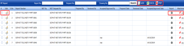
Figure 6.5: MT Report page

6.5.1 Add an MT Report
If you want to add an MT report, do the following steps,
-
Click
 (ADD button) in the MT Report page. See Fig 6.5.
The MT Report page shows a new window opens to add an MT report.
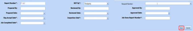
 Note: The fields notified with a symbol (*) are mandatory. You must enter the relevant details in that fields before saving.
 Tip: A report number for a new MT report will be updated automatically in the Report Number box.
 - In the NDT By box, select the requisition detail of NDT inspection whether by third party or internal.
- In the NDT Request No box, select an NDT request number from a drop-down list.
-
In the Prepared By box, enter the name of a person who has prepared the MT report.
- In the Prepared Date box, select the prepared date of the MT report.
- In the Reviewed By box, enter the name of a person who has reviewed the MT request.
- In the Reviewed Date box, select the reviewed date of the MT report.
-
In the Accepted/Approved By boxes, enter the name of a person who has accepted/approved the MT report.
- In the Accepted/Approved Date box, select the accepted/approved date of the MT report.
-
Click Save.


The MT report is successfully added and listed in the MT Report page. Once you have added the MT report, you must add MT results for the respective MT report.
6.5.2 Add MT Results
If you want to add the MT results for the respective MT report, do the following,
- Click the respective MT report in the MT Report page. See Fig 6.5.
The MT Report page shows MPT Results and Report Photos window.

Figure 6.5.1: MT Results page
-
In the Inspection Date box, select the date of inspection.
-
In the Test Equipment box, select the test equipment from a drop-down list.
-
In the Description box, enter the description.
-
In the Test Procedure box, select the test procedure from a drop-down list.
-
In the Test Method box, select the test method from a drop-down list.
-
In the Black Magnetic Ink box, select the type of black magnetic ink from a drop-down list.
-
In the Surface Condition box, enter the condition of the surface.
-
In the Light Source box, enter the light source detail.
-
In the White Contrast Paint box, select the type of white contrast paint.
-
In the Material Specification box, enter the material specification.
-
In the Material Thickness box, enter the material thickness value.
-
In the Type of Current box, enter the type of current.
-
In the Lifting Capacity box, select the lifting capacity value.
-
In the Acceptance Criteria box, select the acceptance criteria from a drop-down list.
-
In the Yoke/ Prod Space box, enter the relevant information.
-
In the Particles Type box, select the type of particles from a drop-down list.
-
In the Particles Make & model box, enter the model of the particle including made of materials.
-
In the Background Contrast & Type box, enter the type of background including contrast range.
- In the Demagnetization box, if you want demagnetization select Yes otherwise select No.
- In the Magnetizing Technique box, enter the magnetizing technique.
-
In the Surface Temperature box, enter the surface temperature value.
-
In the Code box, enter the code detail.
-
In the Color box, select any color from the specified options.
-
In the Suspension box, select any suspension liquid from the specified options.
-
In the Lighting box, select any lighting from the specified options.
-
In the Method box, select any method from the specified options.
-
In the Item Tested box, select the tested items from the specified options.
-
In the Examination Stage box, select the examination stage from the specified options.
-
In the Remarks box, enter your remarks if any.
-
Click Save MPT Details.
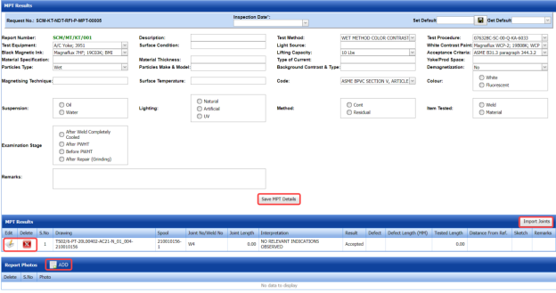
The MT details are successfully updated. Once you have updated the MT details, you must add MT inspection results for the added joints.
 Note: Once you have added MT details, you can save the added MT details and reuse the saved details while you adding MT details for any other MT report.

- To save the added MT details, enter any name in the Set Default box and click.
The added details will be saved in the given name.
-
If you want to add the same MT details for any other MT report, select the name in the Get Default.
The saved details will be automatically updated in the respective boxes.
6.5.2.1 Add MT Results for Joints
The MPT Results window shows a list of joints added for the MT inspection. If you want to add MT results for joints,
- Click
 (Edit icon) for the respective joint listed in the MPT Results window.
The MPT Results window opens a new window with the added MT details.

-
In the Result box, update your MT inspection results whether Accepted, Rejected, or Cancelled.
- In the Remarks box, enter your remarks if any.
-
Click Save.


6.5.2.2 Import Additional joints
If you want to import joints for the updated MPT results,
-
Click
 (Import Joints button) in the MPT Results window. See Fig 6.5.1.
The Joints window opens with a list of joints.

-
Select the joints you want to import.
- Click
 (Import Selected Joints button).
The selected joints are added and listed in the MPT results window. You must add the MT inspection results for the added joints.


6.5.2.3 Add Report Photos
If you want to add any report photos for the updated MT results,
-
Click (ADD button) in the Report Photos box in the MPT Results window. See Fig 6.5.1.

-
Click
 (Browse button) to browse a photo stored in your computer.
 -
Click Upload.


The selected photo will be updated.
6.5.3 Attach a File into an MT Report
If you want to attach any file with any MT report listed in the MT Report page, you can attach the file by using  (Attach icon) in the Attachment column. To know how to attach, follow the procedures given in the topic “Attach a file into P&ID”.
6.5.4 View an NDT – MT Report
If you want to view an NDT - MT report, click  (print icon) provided in the Report column of the MT Report page. See Fig 6.5.
6.5.5 Edit a MT Report
If you want to edit any existing MT report in the MT Report page, do the following steps,
- Click
 (Edit icon) in the Edit column for the respective MT report. See Fig 6.5.
A new window opens to edit the MT report.

-
Click any box where you want to edit the details, and then edit the details in the respective box.
-
Click Save.

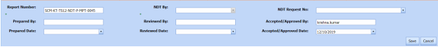
6.5.6 Export MT Report List
You can export a list of RT reports added in the RT Report page in both the pdf and excel formats by using  (PDF button) and
  (Excel button). To know how to export, see the topic, “Export P&ID list”.
6.5.7 Filter a MT Report
If you want to filter any MT report, do one of the following,

- If you want to filter any MT report based on the report number, enter the corresponding report number in the Report No box in the MT Report page, and then Click Search.
- If you want to filter any MT report based on the request number, enter the corresponding request number in the Request No box in the MT Report page, and then Click Search.
- If you want to filter any MT report based on the drawing number, enter the corresponding drawing number in the Drawing No box in the MT Report page, and then Click Search.
6.6 Phased Array Ultrasonic Testing (PAUT) Inspection
PAUT is an advanced NDT inspection technique that utilizes multiple UT probes to inspect more complex geometries. PAUT used to inspect almost any material where traditional UT methods have been utilized for weld inspections and crack detection.
The PAUT tab in the Piping menu helps you to add a PAUT report. Once the NDT inspection request is added with the selection of PAUT type by using the NDT Inspection Request tab, the added inspection request will be moved here.
After completing the PAUT inspection, you can add the PAUT inspection result details by using this PAUT tab. To navigate to PAUT,
-
Click PAUT in the Piping menu.
The PAUT Report page opens.


Figure 6.6: PAUT Report page
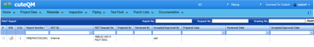
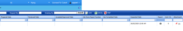
6.6.1 Add a PAUT Report
If you want to add a PAUT report, do the following steps,
- Click
 (ADD button) in the PAUT Report page. See Fig 6.6.
The PAUT Report page shows a new window to add the details of a PAUT report.
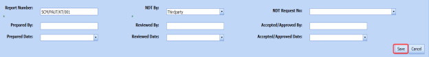
 Note: The fields notified with a symbol (*) are mandatory. You must enter the relevant details in that fields before saving.
 Tip: A report number for a new PAUT report will be updated automatically in the Report Number box. If you want to change the report number, you can change.
 -
In the NDT By box, select the requisition detail of NDT whether by third party or internal.
-
In the NDT Request No box, select an NDT request number from a drop-down list.
-
In the Prepared By box, enter the name of a person who has prepared the PAUT report.
-
In the Prepared Date box, select the prepared date of the PAUT report.
-
In the Reviewed By box, enter the name of a person who has reviewed the PAUT report.
-
In the Reviewed Date box, select the reviewed date of the PAUT report.
- In the Accepted/ Approved By boxes, enter the name of a person who has approved the PAUT report.
-
In the Accepted/ Approved Date box, select the approved date of the PAUT report.
-
Click Save.


The PAUT report is successfully added and listed in the PAUT Report page. Once you have added the PAUT report, you must add PAUT inspection result details.
6.6.2 Add PAUT Inspection Results
If you want to add the PAUT results for the respective PAUT report, do the following steps,
-
Click the respective PAUT report in the PAUT Report page. See Fig 6.6.
The PAUT Report page shows Joint Results, PAUT Results, and Report Photos windows.
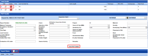
Figure 6.6.1: PAUT Results adding page
-
In the Inspection Date box, select the date of inspection.
-
In the Material Thickness box, enter the thickness of the material.
-
In the Selection of IQI box, select an IQI from a drop-down list.
-
In the Source and Size (MM) box, select a source from a drop-down list.
-
In the Material box, enter the name of the material.
-
In the Density box, enter the density value of the material.
-
In the Acceptance Standard/Code box, select the acceptance standard/code from a drop-down list.
-
In the Procedure Number box, select the procedure number from a drop-down list.
-
In the Sensitivity box, set the sensitivity value of the material.
-
In the Developing Time (Mins) box, set the developing time.
-
In the Film Type box, select the type of film.
-
In the Surface Condition box, enter the surface condition detail.
-
In the Source to Object Distance (SOD) box, enter the distance value from source to object.
-
In the Placement of IQI box, enter the placement detail of IQI.
-
In the Lead Screens box, enter the lead screens detail.
-
In the Density through IQI box, enter the density through IQI detail.
-
In the Front and Back boxes, enter the front and back details.
-
In the Location Marker box, enter the location marker detail.
-
In the Densitometer Serial Number box, enter the densitometer serial number.
-
In the Visible Wire/Hole box, enter the detail of visible wire/hole.
-
In the Remarks box, enter your remarks if any.
-
Click Save PAUT Details.
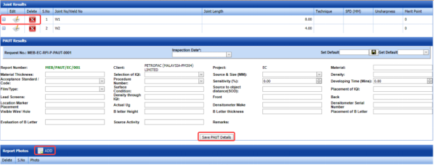
The PAUT details are successfully updated. Once you have updated the PAUT details, you must add the PAUT inspection results for joints in the Joint Results window.
 Note: Once you have added PAUT details, you can save the added PAUT details and reuse the saved details while you adding PAUT details for any other PAUT report.

- To save the added PAUT details, enter any name in the Set Default box and click .
The added details will be saved in the given name.
- If you want to add the same PAUT details for any other PAUT report, select the name in the Get Default.
The saved details will be automatically updated in the respective boxes.
6.6.2.1 Add PAUT Results for Joints
The Joint Results window shows a list of joints added for the PAUT inspection. If you want to add PAUT results for joints,
- Click
 (Edit icon) for the respective joint listed in the Joint Results window.
The Joint Results window opens a new window with the added joint details.

- In the Result box, update your PWHT inspection results whether Accepted, Rejected, or Cancelled.
-
In the Remarks box, enter your remarks if any.
-
Click Save.


6.6.2.2 Add Report Photos
If you want to add any report photos for the updated PAUT results,
-
Click
 (ADD button) in the Report Photos window. See Fig 6.6.1.
- Click
 (Browse button) to browse a photo stored in your computer.
 -
Click Upload.


The selected photo will be updated.
6.6.3 Attach a File into a PAUT Report
If you want to attach any file with any PAUT report listed in the PAUT Report page, you can attach the file by using  (Attach icon) in the Attachment column. To know how to attach, follow the procedures given in the topic “Attach a file into P&ID”.
6.6.4 View a PAUT Report
If you want to view a PAUT report, click  (print icon) provided in the Report column of the PAUT Report page. See Fig 6.6.
6.6.5 Edit a PAUT Report
If you want to edit any existing PAUT report in the PAUT Report page, do the following,
- Click
 (Edit icon) in the Edit column for the respective PAUT report. See Fig 6.6.
The PAUT Report page shows the details of the added PAUT report.
-
Click any box where you want to edit the details, and then edit the details in the respective box.
-
Click Save.

6.6.6 Export PAUT Report List
You can export a list of PAUT reports added in the PAUT Report page in both the pdf and excel formats by using  (PDF button) and
  (Excel button). To know how to export, see the topic, “Export P&ID list”.
6.6.7 Filter a PAUT Report
If you want to filter any PAUT report,

- If you want to filter any PAUT report based on the report number, enter the corresponding report number in the Report No box in the PAUT Report page, and then Click Search.
- If you want to filter any PAUT report based on the request number, enter the corresponding request number in the Request No box in the PAUT Report page, and then Click Search.
- If you want to filter any PAUT report based on the drawing number, enter the corresponding drawing number in the Drawing No box in the PAUT Report page, and then Click Search.
6.7 Time of Flight Diffraction (TOFD) Inspection
TOFD is a reliable method of NDT- UT used to look for flaws in welds. TOFD uses the time of flight of an ultrasonic pulse to find the location of a reflector. TOFD can also be used for weld overlays in piping.
The TOFD tab in the Piping menu helps you to add a TOFD report. Once the NDT inspection request is added with the selection of TOFD type by using the NDT Inspection Request tab, the added inspection request will be moved here.
After completing the TOFD inspection, you can add the TOFD inspection result details by using this TOFD tab. To navigate to TOFD,
-
Click TOFD in the Piping menu.
The TOFD Report page opens.
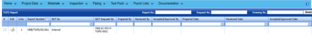

Figure 6.7: TOFD Report page


6.7.1 Add a TOFD Report
If you want to add a TOFD report, do the following steps,
- Click
 (ADD button) in the TOFD Report See Fig 6.7.
The TOFD Report page shows a new window to add the details of a TOFD report.

 Note: The fields notified with a symbol (*) are mandatory. You must enter the relevant details in that fields before saving.
 Tip: A report number for a new TOFD report will be updated automatically in the Report Number box. If you want to change the report number, you can change.
 - In the NDT By box, select the requisition detail of NDT whether by third party or internal.
-
In the NDT Request No box, select an NDT request number from a drop-down list.
-
In the Prepared By box, enter the name of a person who has prepared the TOFD report.
-
In the Prepared Date box, select the prepared date of the TOFD report.
-
In the Reviewed By box, enter the name of a person who has reviewed the TOFD report.
-
In the Reviewed Date box, select the reviewed date of the TOFD report.
-
In the Accepted/ Approved By boxes, enter the name of a person who has approved the TOFD report.
-
In the Accepted/ Approved Date box, select the approved date of the TOFD report.
-
Click Save.

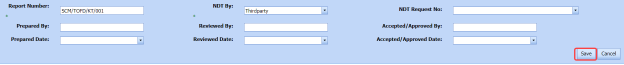


The TOFD report is successfully added and listed in the TOFD Report page. Once you have added the TOFD report, you must add TOFD inspection result details.
6.7.2 Add TOFD Inspection Results
If you want to add the TOFD results for the respective TOFD report, do the following steps,
-
Click the respective TOFD report in the TOFD Report page. See Fig 6.7.
The TOFD Report page shows Joint Results, TOFD Results, and Report Photos windows.
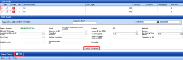
Figure 6.7.1: TOFD Results adding page
-
In the Inspection Date box, select the date of inspection.
-
In the Material Thickness box, enter the thickness of the material.
-
In the Selection of IQI box, select an IQI from a drop-down list.
-
In the Source and Size (MM) box, select a source from a drop-down list.
-
In the Material box, enter the name of the material.
-
In the Density box, enter the density value of the material.
-
In the Acceptance Standard/Code box, select the acceptance standard/code from a drop-down list.
-
In the Procedure Number box, select the procedure number from a drop-down list.
-
In the Sensitivity box, set the sensitivity value of the material.
-
In the Developing Time (Mins) box, set the developing time.
-
In the Film Type box, select the type of film.
-
In the Surface Condition box, enter the surface condition detail.
-
In the Source to Object Distance (SOD) box, enter the distance value from source to object.
-
In the Placement of IQI box, enter the placement detail of IQI.
-
In the Lead Screens box, enter the lead screens detail.
-
In the Density through IQI box, enter the density through IQI detail.
-
In the Remarks box, enter your remarks if any.
-
Click Save TOFD Details.
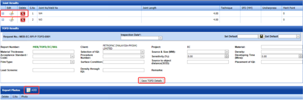
The TOFD details are successfully updated. Once you have updated the TOFD details, you must add the TOFD inspection results for joints in the Joint Results window.
 Note: Once you have added TOFD details, you can save the added TOFD details and reuse the saved details while you adding TOFD details for any other TOFD report.
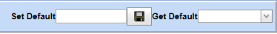
- To save the added TOFD details, enter any name in the Set Default box and click .
The added details will be saved in the given name.
- If you want to add the same TOFD details for any other TOFD report, select the name in the Get Default.
The saved details will be automatically updated in the respective boxes.
6.7.2.1 Add TOFD Results for Joints
The Joint Results window shows a list of joints added for the TOFD inspection. If you want to add TOFD results for joints,
-
Click
 (Edit icon) for the respective joint listed in the Joint Results window.
The Joint Results window opens a new window with the added joint details.
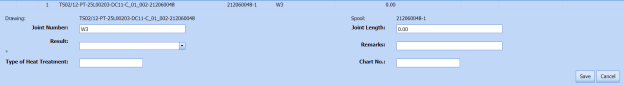
-
In the Result box, update your PWHT inspection results whether Accepted, Rejected, or Cancelled.
- In the Remarks box, enter your remarks if any.
-
Click Save.


6.7.2.2 Add Report Photos
If you want to add any report photos for the updated TOFD results,
- Click
 (ADD button) in the Report Photos See Fig 6.7.1.

- Click
 (Browse button) to browse a photo stored in your computer.
 -
Click Upload.


The selected photo will be updated.
6.7.3 Attach a File into a TOFD Report
If you want to attach any file with any TOFD report listed in the TOFD Report page, you can attach the file by using  (Attach icon) in the Attachment column. To know how to attach, follow the procedures given in the topic “Attach a file into P&ID”.
6.7.4 View a TOFD Report
If you want to view a TOFD report, click (print icon) provided in the Report column of the PAUT Report page. See Fig 6.7.
6.7.5 Edit a TOFD Report
If you want to edit any existing TOFD report in the TOFD Report page, do the following,
- Click
 (Edit icon) in the Edit column for the respective TOFD report. See Fig 6.7.
The TOFD Report page shows the details of the added TOFD report.
- Click any box where you want to edit the details, and then edit the details in the respective box.
-
Click Save.

6.7.6 Export TOFD Report List
You can export a list of TOFD reports added in the TOFD Report page in both the pdf and excel formats by using  (PDF button) and
  (Excel button). To know how to export, see the topic, “Export P&ID list”.
6.7.7 Filter a TOFD Report
If you want to filter any TOFD report,

- If you want to filter any TOFD report based on the report number, enter the corresponding report number in the Report No box in the TOFD Report page, and then Click Search.
-
If you want to filter any TOFD report based on the request number, enter the corresponding request number in the Request No box in the TOFD Report page, and then Click Search.
- If you want to filter any TOFD report based on the drawing number, enter the corresponding drawing number in the Drawing No box in the TOFD Report page, and then Click Search.
6.8 Post Weld Heat Treatment (PWHT)
The PWHT tab in the Piping menu helps you to add a PWHT report. Once the NDT inspection request is added with the selection of PWHT type by using the NDT Inspection Request tab, the added inspection request will be moved here.
After completing the PWHT inspection, you can add the PWHT inspection result details by using this PWHT tab. To navigate to PWHT,
- Click PWHT in the Piping menu.
The PWHT Report page opens.
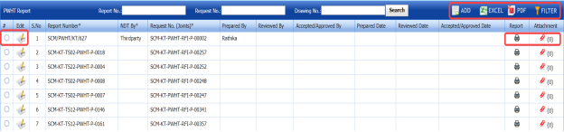
Figure 6.8: PWHT Report page

6.8.1 Add a PWHT Report
If you want to add a PWHT report, do the following,
- Click
 (ADD button) in the PWHT Report See Fig 6.8.
The PWHT Report page shows a new window to add a PWHT report.

 Note: The fields notified with a symbol (*) are mandatory. You must enter the relevant details in that fields before saving.
 Tip: A report number for a new PWHT report will be updated automatically in the Report Number box. If you want to change the report number, you can change.
 - In the NDT By box, select the requisition detail of NDT whether by third party or internal.
- In the Request Number box, select an NDT request number from a drop-down list.
- In the Prepared By box, enter the name of a person who has prepared the PWHT report.
- In the Prepared Date box, select the prepared date of the PWHT report.
- In the Reviewed By box, enter the name of a person who has reviewed the PWHT report.
- In the Reviewed Date box, select the reviewed date of the PWHT report.
- In the Reviewed Date box, select the reviewed date of the PWHT report.
-
In the Accepted/ Approved Date box, select the approved date of the PWHT report.
-
Click Save.

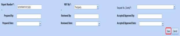


The PWHT report is successfully added and listed in the PWHT Report page. Once you have added the PWHT report, you must add PWHT inspection result details.
6.8.2 Add PWHT Results
If you want to add the PWHT results for the respective PWHT report, do the following steps,
- Click the respective PWHT report in the PWHT Report See Fig 6.8.
The PWHT Report page shows PWHT Results, Joint Results, and Report Photos windows.
 Figure 9.8.1: PWHT Results page
 -
In the Inspection Date box, select the inspection date.
-
In the Material Specification box, enter the specification for the material.
-
In the Governing Thickness box, enter the governing thickness value.
-
In the Governing Code/Specification box, enter the governing code/specification.
-
In the HT Procedure No box, select the HT procedure number.
-
In the No. of Thermo Couple box, enter the number of thermo couple.
-
In the Controlled Heating Rate box, enter the controlled heating rate value.
-
In the Heating Rate From (Temperature) box, enter the heating rate starting range.
-
In the Soaking Temperature box, enter the soaking temperature value.
-
In the Soaking Time box, enter the soaking time value.
-
In the Controlled Cooling Rate box, enter the range of controlled cooling rate.
-
In the Cooling Rate Up to (Temperature) box, enter the cooling rate temperature range.
-
In the Soaking Temperature box, enter the soaking temperature value.
-
In the Remarks box, enter your remarks if any.
-
In the Result box, enter your PWHT result.
-
Click Save PWHT Details.
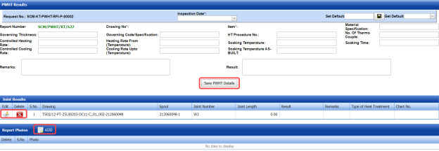
The PWHT details are successfully updated. Once you have updated the PWHT details, you must add the PWHT inspection results for joints in the Joint Results window.
 Note: Once you have added PWHT details, you can save the added PWHT details and reuse the saved details while you adding PWHT details for any other PWHT report.

- To save the added PWHT details, enter any name in the Set Default box and click .
The added details will be saved in the given name.
- If you want to add the same PWHT details for any other PWHT report, select the name in the Get Default.
The saved details will be automatically updated in the respective boxes.
6.8.21 Add PWHT Results for Joints
The Joint Results window shows a list of joints added for the PWHT inspection. If you want to add PWHT results for joints,
- Click
 (Edit icon) for the respective joint listed in the Joint Results window.
The Joint Results window opens a new window with the added joint details.

- In the Result box, update your PWHT inspection results whether Accepted, Rejected, or Cancelled.
-
In the Remarks box, enter your remarks if any.
-
Click Save.


6.8.2.2 Add Report Photos
If you want to add any report photos for the updated PWHT results,
- Click (ADD button) in the Report Photos window. See Fig 6.8.1.

- Click
 (Browse button) to browse a photo stored in your computer.
 -
Click Upload.


The selected photo will be updated.
6.8.3 Attach a File into a PWHT Report
If you want to attach any file with any PWHT report listed in the PWHT Report page, you can attach the file by using  (Attach icon) in the Attachment column. To know how to attach, follow the procedures given in the topic “Attach a file into P&ID”.
6.8.4 View a PWHT Report
If you want to view a PWHT report, click (print icon) provided in the Report column of the PWHT Report page. See Fig 6.8.
6.8.5 Edit a PWHT Report
If you want to edit any existing PWHT report in the PWHT Report page, do the following,
- Click
 (Edit icon) in the Edit column for the respective PWHT report. See Fig 6.8.
The PWHT Report page shows the details of the added PWHT report.
- Click any box where you want to edit the details, and then edit the details in the respective box.
-
Click Save.

6.8.6 Export PWHT Report List
You can export a list of PWHT reports added in the PWHT Report page in both the pdf and excel formats by using  (PDF button) and
  (Excel button). To know how to export, see the topic, “Export P&ID list”.
6.8.7 Filter a PWHT Report
If you want to filter any PWHT report,
- Use
 (FILTER button) in the PWHT Report page, See Fig 6.8. (OR)
 -
Do one of the following steps to filter the PWHT report,

-
-
If you want to filter any PWHT report based on the report number, enter the corresponding report number in the Report No box in the PWHT Report page, and then Click Search.
- If you want to filter any PWHT report based on the request number, enter the corresponding request number in the Request No box in the PWHT Report page, and then Click Search.
- If you want to filter any PWHT report based on the drawing number, enter the corresponding drawing number in the Drawing No box in the PWHT Report page, and then Click Search.
-
-


6.9 Positive Material Identification (PMI)
PMI is one of the more specialized NDT methods. With positive material identification, the alloy composition of materials can be determined.
PMI is one of the more specialized NDT methods. With positive material identification, the alloy composition of materials can be determined.
After completing the PMI inspection, you can add the PMI inspection result details by using this PMI tab. To navigate to PMI,
- Click PMI in the Piping menu.
The PMI Report page opens.
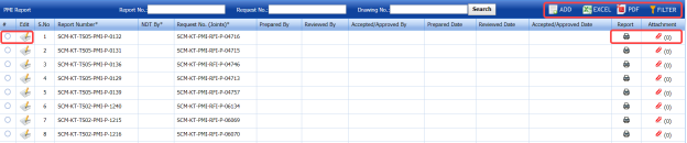
Figure 6.9: PMI Report page

6.9.1 Add a PMI Report
If you want to add a PMI report, do the following,
-
Click
 (ADD button) in the PMI Report page. See Fig 6.9.
The PMI Report page shows a new window to add a new PMI report.
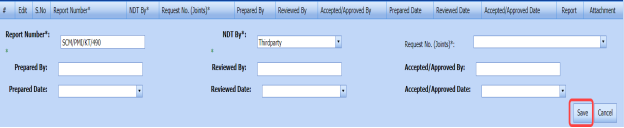
 Note: The fields notified with a symbol (*) are mandatory. You must enter the relevant details in that fields before saving.
 Tip: A report number for a new PMI report will be updated automatically in the Report Number box. If you want to change the report number, you can change.
 - In the NDT By box, select the requisition detail of NDT whether by third party or internal.
- In the Request No box, select an NDT request number from a drop-down list.
- In the Prepared By box, enter the name of a person who has prepared the PMI report.
- In the Prepared Date box, select the prepared date of the PMI report.
- In the Reviewed By box, enter the name of a person who has reviewed the PMI report.
- In the Reviewed Date box, select the reviewed date of the PMI report.
- In the Accepted/ Approved By boxes, enter the name of a person who has approved the PMI report.
- In the Accepted/ Approved Date box, select the approved date of the PMI report.
-
Click Save.


The PMI report is successfully added and listed in the PMI Report page. Once you have added the PMI report, you must add PMI inspection result details.
6.6.2 Add PMI Results
If you want to add the PMI results for the respective PMI report, do the following steps,
- Click the respective PMI report in the PMI Report See Fig 6.9.
The PMI Report page shows PMI Results, PMI Elements, PMI Joint Details, and Report Photos windows.

Figure 9.9.1: PMI Results page
- In the Inspection Date box, select the inspection date.
- In the Test Equipment box, select the test equipment from a drop-down list.
-
In the Material Spec box, select the material specification from a drop-down list.
- In the Text Range box, enter the detail of text range.
- In the Examination Stage box, select the examination stage from the given options.
- Click Save PMI Details.
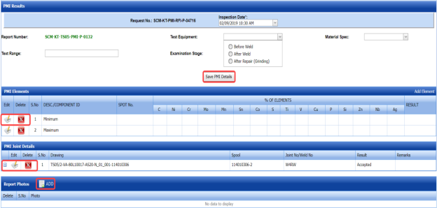
The PMI details are successfully updated. Once you have updated the PMI details, you must add the PMI inspection results for the added elements.
6.9.2.1 Add PMI Results for Elements
The PMI Elements window shows a list of elements added for the PMI inspection. If you want to add PMI results for elements,
- Click
 (Edit icon) for the respective element listed in the PMI Elements window.
The PMI Elements window opens a new window on each column with the added element details.

- Enter the relevant details in each column.
- In the Result column, update your PMI inspection results whether Accepted, Rejected, or Cancelled.
- Click Save.

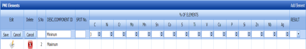
6.9.2.2 Add More Elements
If you want to add more elements, do the following steps,
- Click Add Element in the PMI Elements window.
A new window opens in each column of the PMI Elements window to add a new element.

-
Enter the relevant details in the respective columns.
-
Click Save.
The element is successfully added.
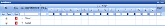
6.9.2.3 Add PMI Results for Joints
The PMI Joint Details window shows a list of joints added for the PMI inspection. If you want to add PMI results for joints,
- Click
 (Edit icon) for the respective joint listed in the PMI Joint Details window.
The PMI Joint Details window opens a new window with the added joint details.

-
In the Result box, update your PMI inspection results whether Accepted, Rejected, or Cancelled.
- In the Remarks box, enter your remarks if any.
- Click Save.

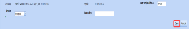
6.9.2.4 Add Report Photos
If you want to add any report photos for the updated PMI results,
- Click
 (ADD button) in the Report Photos window. See Fig 6.9.1.

- Click
 (Browse button) to browse a photo stored in your computer.
 -
Click Upload.
The selected photo will be updated.

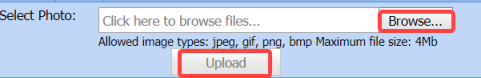

6.9.3 Attach a File into a PMI Report
If you want to attach any file with any PMI report listed in the PMI Report page, you can attach the file by using  (Attach icon) in the Attachment column. To know how to attach, follow the procedures given in the topic “Attach a file into P&ID”.
6.9.4 View a PMI Report
If you want to view a PMI report, click  (print icon) provided in the Report column of the PMI Report page. See Fig 6.9.
6.9.5 Edit a PMI Report
If you want to edit any existing PMI report in the PMI Report page, do the following,
- Click
 (Edit icon) in the Edit column for the respective PMI report. See Fig 6.9.
The PMI Report page shows the details of the added PMI report.
- Click any box where you want to edit the details, and then edit the details in the respective box.
-
Click Save.

6.9.6 Export PMI Report List
You can export a list of PMI reports added in the PMI Report page in both the pdf and excel formats by using  (PDF button) and
  (Excel button). To know how to export, see the topic, “Export P&ID list”.
6.9.7 Filter a PMI Report
If you want to filter any PMI report,
- Use
 (FILTER button) in the PMI Report page, See Fig 6.9. (OR)
 -
Do one of the following steps to filter the PMI report,

-
- If you want to filter any PMI report based on the report number, enter the corresponding report number in the Report No box in the PMI Report page, and then Click Search.
- If you want to filter any PMI report based on the request number, enter the corresponding request number in the Request No box in the PMI Report page, and then Click Search.
- If you want to filter any PMI report based on the drawing number, enter the corresponding drawing number in the Drawing No box in the PMI Report page, and then Click Search.
-


6.10 Ferrite
Ferrite testing, also referred to as a ferrite scope test, is a rapid NDT method used to measure the amount of delta ferrite on materials used in the piping project.
The Ferrite tab in the Piping menu helps you to add a ferrite report. Once the NDT inspection request is added with the selection of ferrite type by using the NDT Inspection Request tab, the added inspection request will be moved here.
The Ferrite tab in the Piping menu helps you to add a ferrite report. Once the NDT inspection request is added with the selection of ferrite type by using the NDT Inspection Request tab, the added inspection request will be moved here.
- Click Ferrite in the Piping menu.
The Ferrite Report page opens.

Figure 6.10: Ferrite Report page

6.10.1 Add a Ferrite Report
If you want to add a ferrite report, do the following steps,
- Click
 (ADD button) in the Ferrite Report page. See Fig 6.10.
The Ferrite Report page shows a new window to add a new ferrite report.
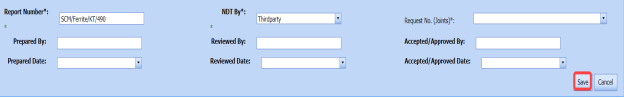
 Note: The fields notified with a symbol (*) are mandatory. You must enter the relevant details in that fields before saving.
 Tip: The report number for a new ferrite report will be updated automatically in the Report Number box. If you want to change the report number, you can change.
 - In the NDT By box, select the requisition detail of NDT whether by third party or internal.
- In the Request No box, select an NDT request number from a drop-down list.
-
In the Prepared By box, enter the name of a person who has prepared the ferrite report.
-
In the Prepared Date box, select the prepared date of the ferrite report.
-
In the Reviewed By box, enter the name of a person who has reviewed the ferrite report.
-
In the Reviewed Date box, select the reviewed date of the ferrite report.
- In the Accepted/ Approved By boxes, enter the name of a person who has approved the ferrite report.
- In the Accepted/ Approved Date box, select the approved date of the PMI report.
- Click Save.
The ferrite report is successfully added and listed in the Ferrite Report page. Once you have added the ferrite report, you must add ferrite inspection result details.


6.10.2 Add Ferrite Inspection Results
If you want to add ferrite inspection results for the respective ferrite report, do the following steps,
- Click the respective ferrite report in the Ferrite Report See Fig 6.10.
The Ferrite Report page shows Ferrite Results, Ferrite Inspection Details, Joint Results, and Report Photos windows.
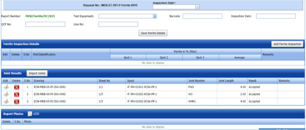
Figure 6.10.1: Ferrite Results page
- In the Inspection Date box, select the date of ferrite inspection.
-
In the Test Equipment box, select the test equipment from a drop-down list.
-
In the Barcode box, enter the barcode of the material.
-
In the Inspection Item box, enter the detail of inspection items.
-
In the QCF No box, enter the QCF number.
-
In the Line No box, enter the line number.
-
Click Save Ferrite Details.

The ferrite details are successfully updated. Once you have updated the ferrite details, you must add the ferrite inspection results.
6.10.2.1 Add Ferrite Inspection Details
If you want to add ferrite inspection details,
-
Click Add Ferrite Inspection in the Ferrite Inspection Details window.
The Ferrite Inspection Details window opens a new window on each column.

-
Enter the relevant details in each column.
-
Click Save.

6.10.2.2 Add Joint Results
The Joint Results window shows a list of joints added for the ferrite inspection. If you want to add ferrite inspection results for joints,
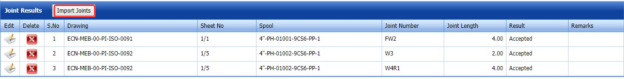
- Click
 (Edit icon) for the respective joint listed in the Joint Results window.
The Joint Results window opens a new window with the added joint details.
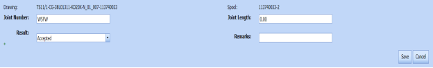
- In the Result box, update your ferrite inspection results whether Accepted, Rejected, or Cancelled.
- In the Remarks box, enter your remarks if any.
-
Click Save.


6.10.2.3 Import Joints
If you want to import multiple joints,
- Click (Import Joints button) in the Joint Results window.
The Joints window opens.

- Select the checkbox of the joints you want to import.
-
Click Import Selected Joints.
The imported joints will be listed in the Joint Results window.
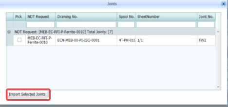
6.10.2.4 Add Report Photos
If you want to add any report photos for the updated ferrite inspection results,
- Click
 (ADD button) in the Report Photos window.

- Click
 (Browse button) to browse a photo stored in your computer.
 -
Click Upload.
The selected photo will be updated.


6.10.3 Attach a File into a Ferrite Report
If you want to attach any file with any ferrite report listed in the Ferrite Report page, you can attach the file by using  (Attach icon) in the Attachment column. To know how to attach, follow the procedures given in the topic “Attach a file into P&ID”.
6.10.4 View a Ferrite Report
If you want to view a ferrite report, click (print icon) provided in the Report column of the Ferrite Report page. See Fig 6.10.
6.10.5 Edit a Ferrite Report
If you want to edit any existing ferrite report in the Ferrite Report page, do the following steps,
- Click
 (Edit icon) in the Edit column for the respective ferrite report. See Fig 6.10.
The Ferrite Report page shows the details of the added ferrite report.
- Click any box where you want to edit the details, and then edit the details in the respective box.
- Click Save.

6.10.6 Export Ferrite Report List
You can export a list of ferrite reports added in the Ferrite Report page in both the pdf and excel formats by using  (PDF button) and
  (Excel button). To know how to export, see the topic, “Export P&ID list”.
6.10.7 Filter a Ferrite Report
If you want to filter any ferrite report,
- Use (FILTER button) in the Ferrite Report page, See Fig 9.10. (OR)
-
Do one of the following steps to filter the ferrite report,

-
-
If you want to filter any ferrite report based on the report number, enter the corresponding report number in the Report No box in the Ferrite Report page, and then Click Search.
- If you want to filter any ferrite report based on the request number, enter the corresponding request number in the Request No box in the Ferrite Report page, and then Click Search.
- If you want to filter any ferrite report based on the drawing number, enter the corresponding drawing number in the Drawing No box in the Ferrite Report page, and then Click Search.
-
-

6.11 Hardness
Harness testing is one of the NDT type of inspection. Hardness testing is performed to evaluate the mechanical properties metal joints and other materials thus helps to ensure that the material meets a particular specification.
The Hardness tab in the Piping menu helps you to add a hardness report. Once the NDT inspection request is added with the selection of hardness type testing by using the NDT Inspection Request tab, the added inspection request will be moved here.
After completing the hardness testing, you can add the hardness testing result details by using this Hardness tab. To navigate to Hardness,
- Click Hardness in the Piping menu.
The Hardness Report page opens.
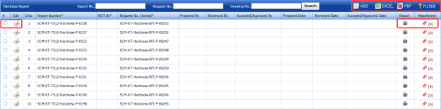
Figure 6.11: Hardness Report page

6.11.1 Add a Hardness Report
If you want to add a hardness report, do the following steps,
- Click
 (ADD button) in the Hardness Report See Fig 6.11.
The Hardness Report page shows a new window to add a new hardness report.
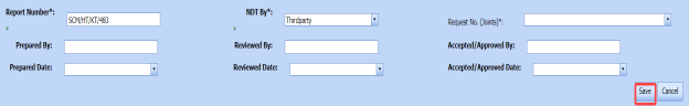
 Note: The fields notified with a symbol (*) are mandatory. You must enter the relevant details in that fields before saving.
 Tip: A report number for a new hardness report will be updated automatically in the Report Number box. If you want to change the report number, you can change.
 - In the NDT By box, select the requisition detail of NDT whether by third party or internal.
-
In the Request No box, select an NDT request number from a drop-down list.
-
In the Prepared By box, enter the name of a person who has prepared the hardness report.
-
In the Prepared Date box, select the prepared date of the hardness report.
-
In the Reviewed By box, enter the name of a person who has reviewed the hardness report.
-
In the Reviewed Date box, select the reviewed date of the hardness report.
- In the Accepted/ Approved By boxes, enter the name of a person who has approved the hardness report.
- In the Accepted/ Approved Date box, select the approved date of the hardness report.
-
Click Save.


The hardness report is successfully added and listed in the Hardness Report page. Once you have added the hardness report, you must add hardness testing result details.
6.11.2 Add Harness Results
If you want to add the hardness testing results for the respective Hardness report, do the following steps,
- Click the respective hardness report in the Hardness Report See Fig 6.11.
The Hardness Report page shows Hardness Results, Joint Results, and Report Photos windows.

Figure 6.11.1: Hardness Results page
-
In the Inspection Date box, select the date of hardness testing.
- In the Part Description box, enter the description of a part to be tested for hardness.
-
In the Weld Map No box, enter the weld map drawing number.
-
In the Material Spec & Grade box, enter the grade and description for the material.
-
In the Instrument box, enter the name of the instrument to be used for hardness testing.
-
In the Instrument Make/ Model/ SL. No. box, enter the instrument model or serial number.
-
In the Intender Type box, enter the type of intender.
-
In the Result box, enter the result of hardness test.
-
In the Procedure No box, select the procedure number from a drop-down list.
-
In the Remarks box, enter your remarks if any.
-
Click Save Hardness Details.
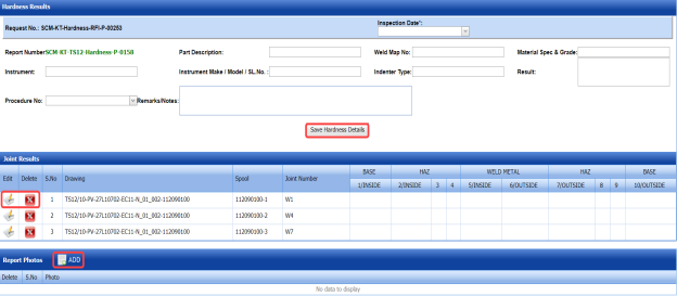
The hardness details are successfully updated. Once you have updated the hardness details, you must add the hardness inspection results for the joints.
6.11.2.1 Add Hardness Testing Results of joints
The Joint Results window shows a list of joints added for the hardness test. If you want to add hardness test results for joints,
- Click
 (Edit icon) for the respective joint listed in the Joint Results window.
The Joint Results window opens a new window for each column with the added joint details.

-
Update your hardness test details in all columns.
-
Click Save.

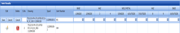
6.11.2.2 Add Report Photos
If you want to add any report photos for the updated hardness test results,
- Click
 (ADD button) in the Report Photos window.

-
Click
 (Browse button) to browse a photo stored in your computer.
 -
Click Upload.
The selected photo will be updated.


6.11.3 Attach a File into a Hardness Report
If you want to attach any file with any hardness report listed in the Hardness Report page, you can attach the file by using (Attach icon) in the Attachment column. To know how to attach, follow the procedures given in the topic “Attach a file into P&ID”.
6.11.4 View a Hardness Report
If you want to view a hardness report, click (print icon) provided in the Report column of the Hardness Report page. See Fig 6.11.
6.11.5 Edit a Hardness Report
If you want to edit any existing hardness report in the Hardness Report page, do the following steps,
- Click
 (Edit icon) in the Edit column for the respective hardness report. See Fig 6.11.
The Hardness Report page shows the details of the added hardness report.
-
Click any box where you want to edit the details, and then edit the details in the respective box.
-
Click Save.

6.11.6 Export Hardness Report List
You can export a list of hardness reports added in the Hardness Report page in both the pdf and excel formats by using  (PDF button) and
  (Excel button). To know how to export, see the topic, “Export P&ID list”.
6.11.7 Filter a Hardness Report
If you want to filter any hardness report,
- Use
 (FILTER button) in the Hardness Report page, See Fig 6.11. (OR)
 - Do one of the following steps to filter the hardness report,

-
- If you want to filter any hardness report based on the report number, enter the corresponding report number in the Report No box in the Hardness Report page, and then Click Search.
- If you want to filter any hardness report based on the request number, enter the corresponding request number in the Request No box in the Hardness Report page, and then Click Search.
-
If you want to filter any hardness report based on the drawing number, enter the corresponding drawing number in the Drawing No box in the Hardness Report page, and then Click Search.
-


6.12 RFI Hydro Pressure Report
The RFI Hydro Pressure Report tab in the Piping menu helps you to add a hydro pressure report in piping project. To navigate to RFI Hydro Pressure Report,
- Click RFI Hydro Pressure Report in the Piping menu.
The Pressure Report page opens.
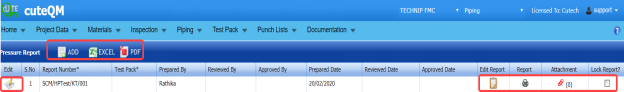
Figure 6.12: Pressure Report page

6.12.1 Add a Hydro Pressure Report
If you want to add a hydro pressure report, do the following steps,
- Click
 (ADD button) in the Pressure Report page. See Fig 6.12.
The Pressure Report page shows a new window to add details of a new hydro pressure report.

 Note: The fields notified with a symbol (*) are mandatory. You must enter the relevant details in that fields before saving.
 Tip: A report number for a new hydro pressure report will be updated automatically in the Report Number box. If you want to change the report number, you can change.
 -
In the Test Pack box, select the test pack from a drop-down list.
-
In the Prepared By box, enter the name of a person who has prepared the hydro pressure report.
-
In the Prepared Date box, select the prepared date of the hydro pressure report.
-
In the Reviewed By box, enter the name of a person who has reviewed the hydro pressure report.
-
In the Reviewed Date box, select the reviewed date of the hydro pressure report.
- In the Approved By boxes, enter the name of a person who has approved the hydro pressure report.
- In the Approved Date box, select the approved date of the hydro pressure report.
-
Click Save.

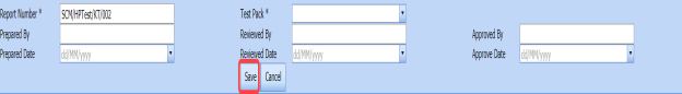


The hydro pressure report is successfully added and listed in the Pressure Report page. Once you have added the hydro pressure report, you must add hydro pressure test details.
6.12.2 Add Hydro Pressure Test Details
If you want to add the hydro pressure test details, do the following steps,
- Click
 (Edit icon) in the Edit Report column of the Pressure Report page. See Fig 6.12.
The Pressure Report page shows Test Parameters, Equipment Details, and Pressure Raise & Reduce Records windows.
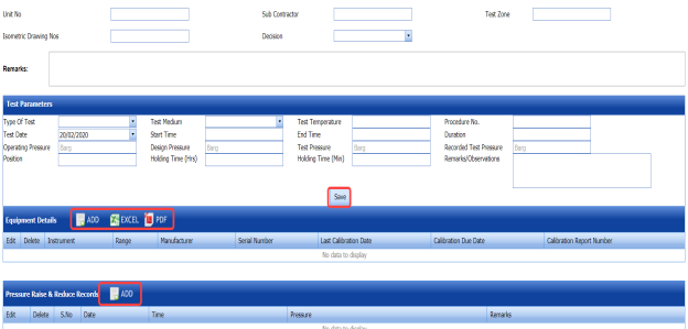
Figure 6.12.1: Pressure Report page
-
In the Unit No box, enter the unit number.
-
In the Sub Contractor box, enter the name of a sub-contractor.
-
In the Test Zone box, enter the detail of test zone.
-
In the Isometric Drawing No box, enter the isometric drawing number.
-
In the Decision box, select your decision whether confirm or non-confirm.
-
In the Remarks box, enter your remarks if any.


6.12.2.1 Add Test Parameters
If you want to add test parameters for the hydro pressure test, enter the following details in the Test Parameters window,
- In the Type of Test box, select the test type from a drop-down list.
-
In the Test Medium box, select the test medium from a drop-down list.
-
In the Test Temperature box, enter the test temperature value.
-
In the Procedure No box, enter the procedure number.
-
In the Test Date box, select the test date.
-
In the Start Time and End Time boxes, enter the start time and end time of test.
-
In the Duration box, enter the duration of test.
-
In the Operating Pressure box, enter the operating pressure value.
- In the Design Pressure box, enter the design pressure value.
-
In the Recorded Test Pressure box, enter the recorded test pressure value.
-
In the Position box, enter the position detail.
-
In the Holding Time (Hrs) box, enter the holding period in hours.
-
In the Holding Time (Min) box, enter the holding period in minutes.
-
In the Remarks/Observations box, enter your remarks/observations if any.
-
Click Save.
6.12.2.2 Add Equipment Details
If you want to add equipment details for the hydro pressure test,
- Click (ADD button) in the Equipment Details window.

- In the Conducted By box, select the method of conducting hydro pressure test whether Internal or
- In the Equipment Details box, select an equipment from a drop-down list.
-
Click Save.
The equipment is successfully added and listed in the Equipment Details window. Once you have added the equipment, you must add the calibration detail for the added equipment.
-
To add calibration detail, click
 (Edit icon) in the Edit column for the equipment.
The Equipment Details windows shows a new window with added equipment details.
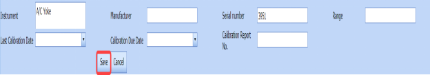
-
In the Manufacturer box, enter the name of the manufacturer.
-
In the Last Calibration Date box, select the last calibration date.
-
In the Calibration Due Date box, select the calibration due date.
-
In the Calibration Report No box, enter the calibration report number.
-
Click Save.
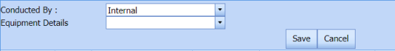

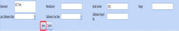
6.12.2.3 Add Pressure Raise and Reduce Records
If you want to add pressure raise and reduce records,
- Click
 (ADD button) in the Pressure Raise & Reduce Records window.
The Pressure Raise & Reduce Records window opens a new window to add the required details.
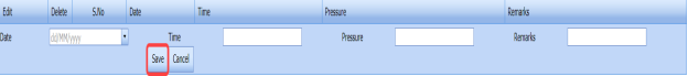
- In the Date box, select the pressure testing date.
-
In the Time box, enter the time of pressure testing.
-
In the Pressure box, enter the pressure value.
-
In the Remarks box, enter your remarks if any.
-
Click Save.


6.12.3 Attach a File into a Hydro Pressure report
If you want to attach any file with any hydro pressure report listed in the Pressure Report page, you can attach the file by using  (Attach icon) in the Attachment column. To know how to attach, follow the procedures given in the topic “Attach a file into P&ID”.
6.12.4 View a Hydro Pressure Report
If you want to view a hydro pressure report, click (print icon) provided in the Report column of the Pressure Report page. See Fig 6.12.
6.12.5 Edit a Hydro Pressure Report
If you want to edit any existing hydro pressure report in the Pressure Report page, do the following steps,
-
Click
 (Edit icon) in the Edit column for the respective hydro pressure report. See Fig 6.12.
The Pressure Report page shows the details of the added pressure report.
- Click any box where you want to edit the details, and then edit the details in the respective box.
-
Click Save.

6.12.6 Export Hydro Pressure Report List
You can export a list of hydro pressure reports added in the Pressure Report page in both the pdf and excel formats by using (PDF button) and
  (Excel button). To know how to export, see the topic, “Export P&ID list”.
6.12.7 Lock a Hydro Pressure Report
If you want to lock any hydro pressure report, select the checkbox of the respective hydro pressure report. See Fig 6.12.
6.13 PMI/Hardness Summary Report
The PMI/HARDNESS Summary Report tab in the Piping menu helps you to view the PMI and hardness summary report. To view the report,
- Click PMI/HARDNESS Summary Report in the Piping menu.
The PMI and Hardness summary report page opens.

Figure 6.13: PMI/Hardness Summary Report page
- If you want to view the PMI summary report, click the PMI option.
The PMI Summary Report opens.
- If you want to view the hardness summary report, click the HARDNESS option.
The Hardness Summary Report opens.
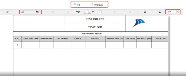
6.13.1 Print a PMI and Hardness Summary Report
If you want to print a PMI/Hardness summary report, use  and
and  (print icons) provided in the PMI and Hardness summary report page.
- If you want to print the current page of the PMI and Hardness summary report, click
 (print icon including the page number).
 -
If you want to print all the pages of the PMI and Hardness summary report, click
 (print icon).


6.13.2 View a PMI and Hardness Summary Report
You can view the PMI and Hardness summary report in various formats by using the option  provided in the upper right corner of the PMI and Hardness summary report page.
6.14 Preheat/PWHT Summary Report
The PREHEAT/PWHT Summary Report tab in the Piping menu helps you to view the Preheat and PWHT summary report. To view the report,
- Click PREHEAT/PWHT Summary Report in the Piping menu.
The Preheat and PWHT summary report page opens.
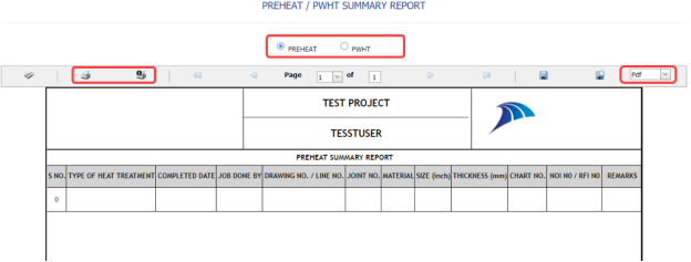
Figure 6.14: Preheat/PWHT Summary Report page
- If you want to view the preheat summary report, click the PREHEAT option.
The Preheat Summary Report opens.
-
If you want to view the PWHT summary report, click the PWHT option.
The PWHT Summary Report opens.

6.14.1 Print a Preheat and PWHT Summary Report
If you want to print a Preheat/PWHT summary report, use  and
and  (print icons) provided in the Preheat and PWHT summary report page.
- If you want to print the current page of the Preheat and PWHT summary report, click
 (print icon including the page number).
 -
If you want to print all the pages of the Preheat and PWHT summary report, click
 (print icon).


6.14.2 View a Preheat and PWHT Summary Report
You can view the preheat and PWHT summary report in various formats by using the option  provided in the upper right corner of the Preheat and PWHT summary report page.
6.15 PAUT Summary Report
The PAUT Summary Report tab in the Piping menu helps you to view the PAUT summary report. To view the report,
- Click PAUT Summary Report in the Piping menu.
The PAUT summary report page opens.
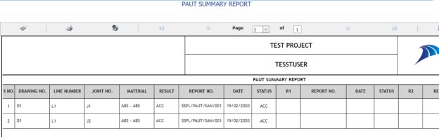
Figure 6.15: PAUT Summary Report page

6.15.1 Print a PAUT Summary Report
If you want to print a PAUT summary report, use  and
and  (print icons) provided in the PAUT summary report page.
- If you want to print the current page of the PAUT summary report, click
 (print icon including the page number).
 - If you want to print all the pages of the PAUT summary report, click
 (print icon).


6.15.2 View a PAUT Summary Report
You can view the PAUT summary report in various formats by using the option  provided in the upper right corner of the PAUT summary report page.
6.16 RT Summary Report
The RT Summary Report tab in the Piping menu helps you to view the RT summary report. To view the report,
- Click RT Summary Report in the Piping menu.
The RT summary report page opens.
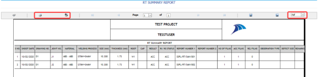
Figure 6.16: RT Summary Report page

6.16.1 Print a RT Summary Report
If you want to print a RT summary report, use  and
and  (print icons) provided in the RT summary report page.
- If you want to print the current page of the RT summary report, click
 (print icon including the page number).
 -
If you want to print all the pages of the RT summary report, click
 (print icon).


6.16.2 View a RT Summary Report
You can view the RT summary report in various formats by using the option  provided in the upper right corner of the RT summary report page.
6.17 Welder Performance Record
The Welder Performance Record tab in the Piping menu helps you to view a performance record of welders. To view the welder performance record,
- Click Welder Performance Record in the Piping menu.
The Welder Performance Record page opens.

Figure 6.17: Welder Performance Record page
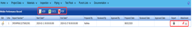
6.17.1 Add a Welder Performance Record
If you want to add a welder performance record, do the following steps,
- Click
 (ADD button) in the Welder Performance Record page.
The page opens a new window to add the details of the welder performance record.
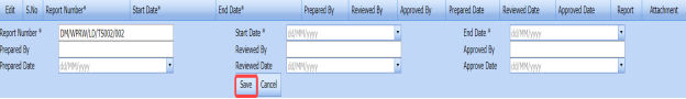
 Tip: The report number for the welder performance record will be updated automatically. If you want to change the report number, you can change.
 - In the Start Date and End Date boxes, select the start and ending dates to view the welder performance record.
-
In the Prepared By box, enter the name a person who has prepared the welder performance record.
- In the Prepared Date box, enter the prepared date of the welder performance record.
-
In the Reviewed By box, enter the name a person who has reviewed the welder performance record.
-
In the Reviewed By box, enter the name a person who has reviewed the welder performance record.
-
In the Approved By box, enter the name a person who has approved the welder performance record.
- In the Approved Date box, enter the approved date of the welder performance record.
- Click Save.
The welder performance record will be added and listed in the Welder Performance Record page.


6.17.2 Edit a Welder Performance Record
If you want to edit any existing welder performance record in the Welder Performance Record page, do the following steps,
- Click
 (Edit icon) in the Edit column for the respective welder performance record. See Fig 6.17.
The Welder Performance Record page shows the details of the added welder performance record.
-
Click any box where you want to edit the details, and then edit the details in the respective box.
- Click Save.

6.17.3 View a Welder Performance Record
If you want to view a welder performance record, click (print icon) provided in the Welder Performance Record page. See Fig 6.17.
6.17.4 Attach a File into a Welder Performance Record
If you want to attach any file with a welder performance record listed in the Welder Performance Record page, you can attach the file by using  (Attach icon) in the Attachment column. To know how to attach, follow the procedures given in the topic “Attach a file into P&ID”.
6.17.5 Export a Welder Performance Record
You can export the welder performance in the Welder Performance Record page in both the pdf and excel formats by using (PDF button) and
  (Excel button). To know how to export, see the topic, “Export P&ID list”.
6.18 Generate Weld Visual Report
The Generate Weld Visual Report tab in the Piping menu helps you to generate a weld visual report.
- Click Generate Weld Visual Report in the Piping menu.
The Daily Pipe Weld Visual Record page opens.
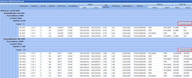
Figure 6.18: Daily Pipe Weld Visual Record page
The Daily Pipe Weld Visual Record page shows the list of weld visual inspections completed on each day including the welding date, weld process name, location, pipe size, and drawing name.
-
-
The Daily Pipe Weld Visual Record page shows the list of weld visual inspections completed on each day including the welding date, weld process name, location, pipe size, and drawing name.
- Each group has a maximum of 20 number of weld visual inspection.
- Each group is separated by different group number.
- You can generate a report for each group individually by using the respective report generating option provided in the Daily Pipe Weld Visual Record page.
-
-
- If you want to generate report of DPWR for any group or date, click
 (Generate Report button) of the respective group or date.

The generated reports will be moved to the Weld Visual Report page. To view the generated reports, navigate to the Weld Visual Report tab.
6.19 Weld Visual Report
The Weld Visual Report tab in the Piping menu helps you to view a weld visual report. Once you have generated the weld visual report, the generated report will be moved here. You can view the respective report by using this tab. To view the weld visual report,
- Click Weld Visual Report in the Piping menu.
The Weld Visual Report page opens.

Figure 6.19: Weld Visual Report page
 Note: If you want to view the welded joints, select the checkbox of the Show Welded Joints option provided in the page. The page shows the list of welded joints.
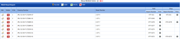

6.19.1 Add Weld Visual Report
If you want to add a weld visual report, do the following steps,
- Click
 (ADD button) in the Weld Visual Report page.
The page opens a new window to add the details of the weld visual report.
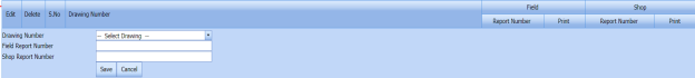
-
In the Drawing Number box, select the drawing number from a drop-down list.
The field report number and shop report number will be updated automatically in the respective boxes.
-
Click Save.
The weld visual report is successfully added and listed in the Weld Visual Report page.


6.19.2 Edit a Weld Visual Report
If you want to edit any existing weld visual report in the Weld Visual Report page, do the following steps,
- Click
 (Edit icon) in the Edit column for the respective weld visual report. See Fig 6.19.
The Weld Visual Report page shows the details of the added report.
- Click any box where you want to edit the details, and then edit the details in the respective box.
-
Click Save.

6.19.3 Delete a Weld Visual Report
If you want to delete any weld visual report in the Weld Visual Report page, you can use  (Delete icon) provided in the Weld Visual Report page. To know how to delete, see the topic, “Delete P&ID”.
6.19.4 View a Weld Visual Report
- If you want to view a weld visual report related with the field inspection, click
 (print icon) provided in the Field column. See Fig 6.19.
 - If you want to view a weld visual report related with the shop inspection, click
 (print icon) provided in the Shop See Fig 6.19.


6.19.5 Filter a Weld Visual Report
If you want to filter any weld visual report in the Weld Visual Report page, you can use  (FILTER button) located on the Weld Visual Report page. To know how to filter, see the topic, “Filter P&ID”.
6.19.6 Export a Weld Visual Report
You can export the weld visual reports in the Weld Visual Report page in both the pdf and excel formats by using (PDF button) and (Excel button). To know how to export, see the topic, “Export P&ID list”.
6.20 Weld Joint Log Sheet
The Weld Joint Log sheet tab in the Piping menu helps you to view a log sheet of pipe welding inspection. To view the log sheet,
- Click Weld Joint Log sheet in the Piping menu.
The pipe welding inspection log sheet page opens.
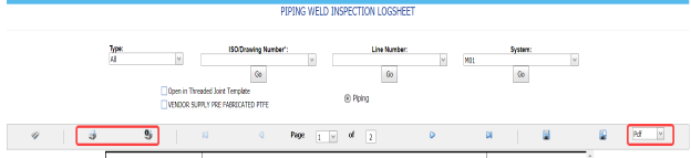
Figure 6.20: Pipe welding inspection log sheet page
-
In the Type box, select the type of joint.
-
Do one of the following steps,
-
- In the ISO Drawing Number box, select the isometric drawing number from a drop-down list.
-
In the Line Number box, select the line number from a drop-down list.
-
In the System box, select the system from a drop-down list.
-
-
Click Go.
- If you want to open the log sheet in a threaded joint template, click the checkbox of the Open in Threaded Joint Template option.
- If you want to open the log sheet in a threaded joint template, click the checkbox of the Open in Threaded Joint Template option.
The pipe welding inspection log sheet opens for the selected option.


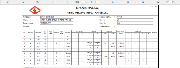
6.20.1 Print a Weld Joint Log sheet
If you want to print the weld joint log sheet, use  and
and  (print icons) provided in the Weld Joint Log sheet page.
- If you want to print the current page of the Weld Joint Log sheet, click
 (print icon including the page number).
 - If you want to print all the pages of the Weld Joint Log sheet, click
 (print icon).


6.20.2 View a Weld Joint Log sheet
You can view the weld joint log sheet in various formats by using the option provided in the upper right corner of the Weld Joint Log sheet page.
6.21 Joint Summary Report
The Joint Summary report tab in the Piping menu used to view a joint summary report. If you want to see a joint summary report,
-
Click Joint Summary Report in the Piping menu.
The Joint Summary Report page shows summary details of isometric drawing, joints, welders, components and so on.
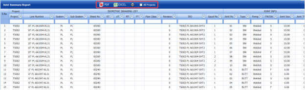
Figure 9.21: Joint Summary Report page

6.21.1 Export a Joint Summary Report
You can export the joint summary report in both the pdf and excel formats by using  (PDF button) and
  (Excel button) in the Joint Summary Report page. To know how to export, see the topic, “Export P&ID list”.
6.21.2 View a Joint Summary Report
If you want to view a joint summary report, click (print icon) provided in the Joint Summary Report page. See Fig 6.21.
6.22 Welding Application Report
The Welding Application Report tab in the Piping menu shows a welding application report.
If you want to view a welding application report,
- Click Welding Application Report in the Piping menu.
The welding application report page opens with the details of welding application.
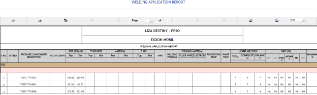
Figure 6.22: Welding Application Report page

6.22.1 Print a Welding Application Report
If you want to print a welding application report, use  and
and  (print icons) provided in the Welding Application Report page. See Fig 6.22.
- If you want to print the current page of the welding application report, click
 (print icon including the page number).
 - If you want to print all the pages of the welding application report, click
 (print icon).


6.22.2 Export a Welding Application Report
You can export the welding application report in various formats by using the option  provided in the upper right corner of the Welding Application Report page.
6.23 Weld Rejection Rate
Weld Rejection Rate is the difference between the tested length and repair length of the welded material, which are calculated using RT and UT inspection. The Weld Rejection Rate is used to calculate the weld success rate.
The Weld Rejection Rate tab in the Piping menu shows a weld rejection rate report including weekly and cumulative weld success rate summary details.
If you want to view a weld rejection rate report,
- Click Weld Rejection Rate in the Piping menu.
The weld rejection rate report page opens.
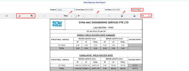
Figure 6.23: Weld Rejection Rate Report page
- In the Project box, select a project for which you want to view a weld rejection rate report, from a drop-down list.
-
In the From Date and To Date boxes, select the from and to dates in respectively.
-
Click Show Report.
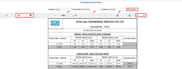
The weld rejection rate report opens for the selected project.
6.23.1 Print a Weld Rejection Rate Report
If you want to print a weld rejection rate report, use  and
and  (print icons) provided in the Weld Rejection Rate Report page. See Fig 6.23.
- If you want to print the current page of the weld rejection rate report, click
 (print icon including the page number).
 -
If you want to print all the pages of the weld rejection rate report, click
 (print icon).


6.23.2 Export a Weld Rejection Rate Report
You can export the weld rejection rate report in various formats by using the option  provided in the upper right corner of the Weld Rejection Rate Report page.
6.24 Weekly/Monthly DPWR
The Weekly/Monthly DPWR tab in the Piping menu used to view a DPWR on a weekly or monthly basis. To view a DPWR,
-
Click Weekly/Monthly DPWR in the Piping menu.
The DPWR page opens.
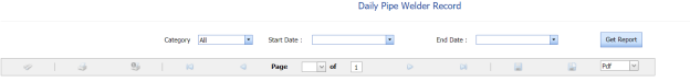
-
In the Category box, select the category from a drop-down list.
- In the Start Date and End Date boxes, select the starting and ending date to view the DPWR.
- Click Get Report.
The DPWR page shows the welder details for the selected category and period.


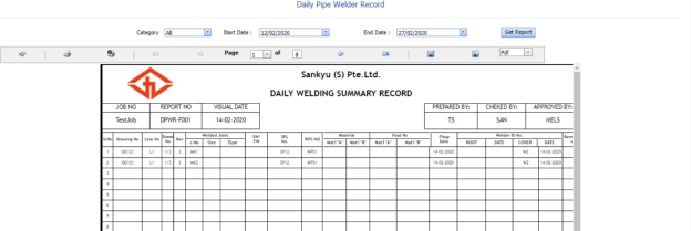
6.24.1 Print a Weekly/Monthly DPWR
If you want to print the DPWR, use  and
and  (print icons) provided in the DPWR page. See Fig 6.24.
- If you want to print the current page of the DPWR, click
 (print icon including the page number).
 -
If you want to print all the pages of the DPWR, click
 (print icon).


6.24.2 Export a Weekly/Monthly DPWR
You can export the DPWR in various formats by using the option  provided in the upper right corner of the DPWR page.
6.25 Piping Inspection Completion Status by System
The Status by System tab in the Piping menu used to view the completed status of the piping inspection based on the system data. To view the status,
- Click Status by System in the Piping menu.
The Piping Inspection Completion Status by System page opens and shows the NDT inspection details.

Figure 6.25: Piping Inspection Completion Status by System page
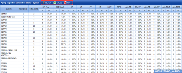
6.25.1 Export Piping Inspection Completion Status by System
You can export the piping inspection completion status in the Piping Inspection Completion Status by System page in both the pdf and excel formats by using  (PDF button) and
  (Excel button). To know how to export, see the topic, “Export P&ID list”.
6.25.2 Filter Piping Inspection Completion Status by System
If you want to filter any piping inspection completion status, you can use  (FILTER button) in the Piping Inspection Completion Status by System page. To know how to filter, see the topic, “Filter P&ID”.
6.26 Piping Inspection Completion Status by Sub System
The Status by Sub System tab in the Piping menu used to view the completed status of the piping inspection based on the sub system data. To view the status,
- Click Status by Sub System in the Piping menu.
The Piping Inspection Completion Status by Sub System page opens and shows the NDT inspection details.
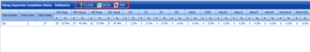
Figure 6.26: Piping Inspection Completion Status by Sub System page

6.26.1 Export Piping Inspection Completion Status by Sub System
You can export the piping inspection completion status in the Piping Inspection Completion Status by Sub System page in both the pdf and excel formats by using  (PDF button) and
  (Excel button). To know how to export, see the topic, “Export P&ID list”.
6.26.2 Filter Piping Inspection Completion Status by Sub System
If you want to filter any piping inspection completion status, you can use (FILTER button) in the Piping Inspection Completion Status by Sub System page. To know how to filter, see the topic, “Filter P&ID”.
6.27 Piping Inspection Completion Status by Line
The Status by Line tab in the Piping menu used to view the completed status of the piping inspection based on the Lines data. To view the status,
- Click Status by Line in the Piping menu.
The Piping Inspection Completion Status by Line page opens and shows the NDT inspection details.
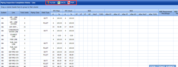
Figure 9.27: Piping Inspection Completion Status by Line page

6.27.1 Export Piping Inspection Completion Status by Line
You can export the piping inspection completion status in the Piping Inspection Completion Status by Line page in both the pdf and excel formats by using  (PDF button) and
  (Excel button). To know how to export, see the topic, “Export P&ID list”.
6.27.2 Filter Piping Inspection Completion Status by Line
If you want to filter any piping inspection completion status, you can use  (FILTER button) in the Piping Inspection Completion Status by Line page. To know how to filter, see the topic, “Filter P&ID”.
6.28 Piping Inspection Completion Status by ISO
The Status by ISO tab in the Piping menu used to view the completed status of piping inspection based on the isometric drawing data. To view the status,
- Click Status by ISO in the Piping menu.
The Piping Inspection Completion Status by ISO page opens and shows the drawing status and NDT inspection details.

Figure 6.28: Piping Inspection Completion Status by ISO page
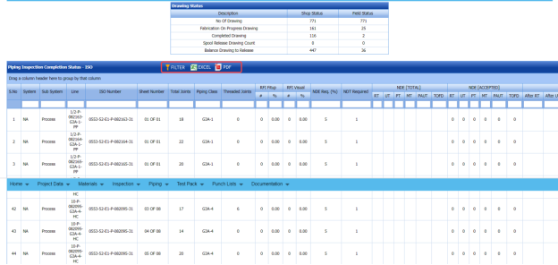
6.28.1 Export Piping Inspection Completion Status by ISO
You can export the piping inspection completion status in the Piping Inspection Completion Status by ISO page in both the pdf and excel formats by using  (PDF button) and
  (Excel button). To know how to export, see the topic, “Export P&ID list”.
6.28.2 Filter Piping Inspection Completion Status by ISO
If you want to filter any piping inspection completion status, you can use  (FILTER button) in the Piping Inspection Completion Status by ISO page. To know how to filter, see the topic, “Filter P&ID”.
6.29 Piping Inspection Completion Status by Spools
The Status by Spools tab in the Piping menu used to view the completed status of piping inspection based on the spool data. To view the status,
-
Click Status by Spools in the Piping menu.
The Piping Inspection Completion Status by Spools page opens and shows the NDT inspection details.

Figure 6.29: Piping Inspection Completion Status by Spools page
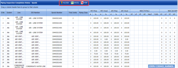
6.29.1 Export Piping Inspection Completion Status by Spools
You can export the piping inspection completion status in the Piping Inspection Completion Status by Spools page in both the pdf and excel formats by using  (PDF button) and
  (Excel button). To know how to export, see the topic, “Export P&ID list”.
6.29.2 Filter Piping Inspection Completion Status by Spools
If you want to filter any piping inspection completion status, you can use  (FILTER button) in the Piping Inspection Completion Status by Spools page. To know how to filter, see the topic, “Filter P&ID”.
6.30 Piping Inspection Completion Status by Test Pack
The Status by Test Pack tab in the Piping menu used to view the completed status of piping inspection based on the test pack data. To view the status,
- Click Status by Test Pack in the Piping menu.
The Piping Inspection Completion Status by Test Pack page opens and shows the NDT inspection details.
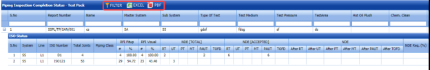
Figure 6.30: Piping Inspection Completion Status by Test Pack page

6.30.1 Export Piping Inspection Completion Status by Test Pack
You can export the piping inspection completion status in the Piping Inspection Completion Status by Test Pack page in both the pdf and excel formats by using  (PDF button) and
  (Excel button). To know how to export, see the topic, “Export P&ID list”.
6.30.2 Filter Piping Inspection Completion Status by Test Pack
If you want to filter any piping inspection completion status, you can use  (FILTER button) in the Piping Inspection Completion Status by Test Pack page. To know how to filter, see the topic, “Filter P&ID”.
6.31 Outstanding Joints
The Outstanding Joints tab in the Piping menu used to view and track the details of outstanding joints. To view the outstanding joints,
- Click Outstanding Joints in the Piping menu.
The Outstanding Joints page opens.

Figure 6.31: Outstanding Joints page
- Select the joint category from the given options such as All, Shop, and Field.
The page shows the details of outstanding joints based on the selected category.

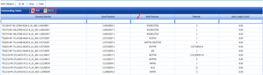
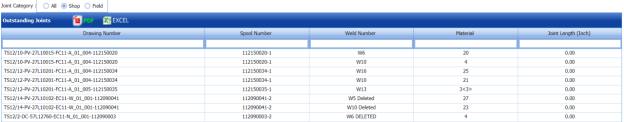
6.3.11 Export Outstanding Joints
You can export the list of outstanding joints in the Outstanding Joints page in both the pdf and excel formats by using  (PDF button) and
  (Excel button). To know how to export, see the topic, “Export P&ID list”.
6.3.12 Filter Outstanding Joints
If you want to filter any specific outstanding, you can use the filter box provided in each column of the Outstanding Joints page.

6.32 Completed Drawings
The Completed Drawings tab in the Piping menu used to view and track the details of completed drawings. To view the completed drawings details,
- Click Completed Drawings in the Piping menu.
The Completed Drawings page opens.
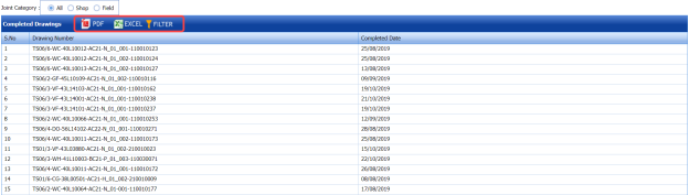
Figure 6.32: Completed Drawings page
- Select the joint category from the given options such as All, Shop, and Field.
The page shows the details of completed drawings based on the selected category.


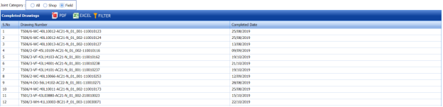
6.32.1 Export Completed Drawings
You can export the list of completed drawings in the Completed Drawings page in both the pdf and excel formats by using  (PDF button) and
  (Excel button). To know how to export, see the topic, “Export P&ID list”.
6.33 Weld Progress by Date
The Weld Progress by Date tab in the Piping menu helps you to view the graphical representation of welding progress on a day basis. To view the welding progress detail,
- Click Weld Progress by Date in the Piping menu.
The Welding Progress page opens with a graphical representation.
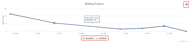
The chart shows the number of welding such as shop weld and field weld, performed on every day.
- If you want to view the progress detail of welding performed in the shop, click Shop Weld.
The chart shows the shop welding progress details.
- If you want to view the progress detail of welding performed in the field, click Field Weld.
The chart shows the field welding progress details.

6.33.1 Print a Welding Progress chart
If you want to print the welding progress chart,
- Click (menu icon) in the Weld Progress page.
-
Click Print Chart.
The chart will be printed.
6.33.2 Download a Welding Progress Chart
You can download the welding progress chart in PNG image, JPEG image, SVG vector image, and PDF formats by using the respective options provided in the menu icon.
6.34 Inspection Request Summary Report
The Inspection Request Summary tab in the Piping menu used to view the summary of inspection request. To view the inspection request summary report,
-
Click Inspection Request Summary in the Piping menu.
The Inspection Request Summary Report page opens.

Figure 6.34: Inspection Request Summary Report page
-
In the Start Date and End Date boxes, select the start and end dates.
-
Click Search.
The page shows the details of inspection request.
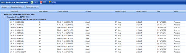
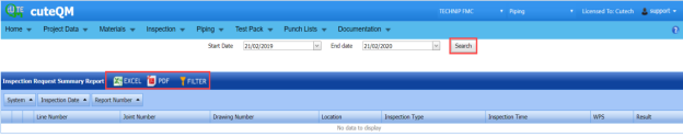

6.34.1 Export an Inspection Request Summary Report
You can export the inspection request summary report in both the pdf and excel formats by using (PDF button) and (Excel button). To know how to export, see the topic, “Export P&ID list”.
6.34.2 Filter an Inspection Request Summary
If you want to filter any inspection request detail, you can use  (FILTER button) in the Inspection Request Summary Report page. To know how to filter, see the topic, “Filter P&ID”.
6.35 Piping Progress Status Report
The Piping Progress Status Report tab in the Piping menu used to view the piping progress status report. To view the piping progress status report,
-
Click Piping Progress Status Report in the Piping menu.
The Piping Progress Status Report page opens.

Figure 9.35: Piping Progress Status Report page
-
In the From Date and To Date boxes, select the from and to dates to view the piping progress status.
-
Click Load Report.
The page shows the details of piping progress status.
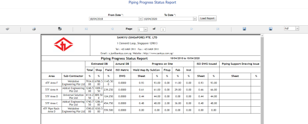

6.35.1 Print a Piping Progress Status Report
If you want to print the piping progress status report, use  and
and  (print icons) provided in the Piping Progress Status Report page. See Fig 6.35.
-
If you want to print the current page of the piping progress status report, click
 (print icon including the page number).
 -
If you want to print all the pages of the piping progress status report, click
 (print icon).


6.35.2 Export a Piping Progress Status Report
You can export the piping progress status report in various formats by using the option  provided in the upper right corner of the Piping Progress Status Report page.
6.36 Welder Defect Analysis Report
The Welder Defect Analysis Report tab in the Piping menu used to view the defect analysis report of the particular welder. To view the welder defect analysis report,
-
Click Welder Defect Analysis Report in the Piping menu.
The Welder Defect Analysis page opens.
Figure 9.36: Welder Defect Analysis page
-
In the Select Welder box, select a welder from the list of welders.
-
Click Generate Report.
The page shows the defect analysis report of the selected welder.
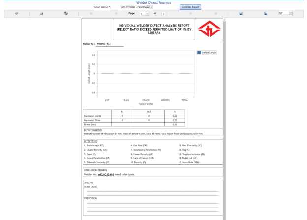


6.36.1 Print a Welder Defect Analysis Report
If you want to print the welder defect analysis report, use  and
and  (print icons) provided in the Welder Defect Analysis page. See Fig 6.36.
- If you want to print the current page of the welder defect analysis report, click
 (print icon including the page number).
 - If you want to print all the pages of the welder defect analysis report, click
 (print icon).


6.36.2 Export a Welder Defect Analysis Report
You can export the welder defect analysis report in various formats by using the option  provided in the upper right corner of the Welder Defect Analysis Report page.
6.37 Weld Traceability Record
The Weld Traceability Record tab in the Piping menu used to add a weld traceability record and track welding records.
If you want add a weld traceability record, do the following,
-
Click Weld Traceability Record in the Piping menu.
The Weld Traceability Record page opens.
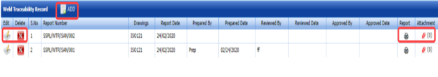
Figure 6.37: Weld Traceability Record page

6.37.1 Add a Weld Traceability Record
If you want to add a weld traceability record, do the following,
- Click
 (ADD button) in the Weld Traceability Record page. See Fig 6.37.
The page opens a new window to add the details of a weld traceability record.

 Note: The field notified with a symbol (*) is mandatory. You must enter the relevant details in that fields before saving.
 Tip: A report number for a new weld traceability record will be updated automatically in the Report Number box. If you want to change the report number, you can change.
 - In the Drawing Number box, select a drawing number from a drop-down list.
-
In the Date box, enter the date of adding the weld traceability record.
- In the Prepared By box, enter the name of a person who has prepared the weld traceability record.
- In the Prepared Date box, select the prepared date of the weld traceability record.
- In the Reviewed By box, enter the name of a person who has reviewed the weld traceability record.
- In the Reviewed Date box, select the reviewed date of the weld traceability record.
- In the Approved By boxes, enter the name of a person who has approved the weld traceability record.
- In the Approved Date box, select the approved date of the weld traceability record.
-
Click Save.
The weld traceability record is successfully added.

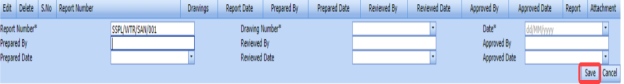


6.37.2 View a Weld Traceability Report
If you want to view a weld traceability report, click  (print icon) provided in the Report column in the Weld Traceability Record page. See Fig 6.37.
6.37.3 Attach a File into a Weld Traceability Record
If you want to attach any file with a weld traceability record listed in the Weld Traceability Record page, you can attach the file by using  (Attach icon) in the Attachment column. To know how to attach, follow the procedures given in the topic “Attach a file into P&ID”.
6.37.4 Edit a Weld Traceability Record
If you want to edit any existing weld traceability record in the Weld Traceability Record page, do the following,
- Click
 (Edit icon) in the Edit column for the respective weld traceability record.
The page shows the added details of the weld traceability record.
-
Click any box where you want to edit the details, and then edit the details in the respective box.
-
Click Save.

6.37.5 Delete a Weld Traceability Record
If you want to delete any existing system in the System page, you can use  (Delete icon) provided in the System page. To know how to delete, see the topic, “Delete P&ID”.
6.38 Add Non-Conformance Report (NCR)
NCR used to document the details of a non-conformance identified in a quality audit or other process review. The Add NCR tab in the Piping menu helps you to add an NCR in the Piping project. Do the following steps to add an NCR,
- Click Add NCR in the Piping menu.
The NCR page opens.
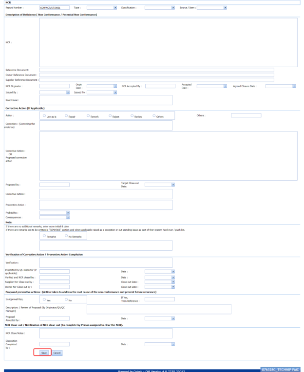
Figure 6.38: NCR page
 Tip: A report number for a new NCR will be updated automatically in the Report Number box. If you want to change the report number, you can change.
 -
In the Type box, select the type of non-conformance from a drop-down list.
- In the Classification box, select whether minor classification or major classification from a drop-down list.
- In the Source/ Item box, select the source of NCR from a drop-down list.
-
In the NCR box, enter the description for the identified deficiency of the selected non-conformance type.
-
In the Reference Document box, enter the reference document detail.
-
In the Owner Reference Document box, enter the owner reference document detail.
-
In the Supplier Reference Document box, enter the supplier reference document detail.
-
In the NCR originator box, enter the originator of NCR.
-
In the Origin Date box, select the origin date of NCR.
-
In the NCR Accepted By box, enter the name of a person who has accepted the NCR.
-
In the NCR Accepted Date box, select the NCR accepted date.
-
In the Agreed Closure Date box, select the agreed closure date.
- In the Issued By box, select the company who has issued the NCR.
- In the Issued To box, select the company for which the NCR has issued.
-
In the Root Cause box, enter the root cause detail.
- If you want to add the corrective action detail, do the following,
-
-
In the Action box, select any corrective action from the given options.
-
In the Corrective Action box, enter the corrective action detail.
- In the Proposed by box, enter the name of a person who has proposed the corrective action.
- In the Target Close-out Date box, select the target close out date.
-
In the Preventive Action box, enter the preventive actions.
- In the Probability box, select the probability percentage of non-conformance.
- In the consequences box, select the consequences level you have faced.
-
-
-
If you want to add any remarks, click Remarks option and enter your remarks, otherwise click No Remarks option.
-
In the Verification box, enter the verification detail on completion of corrective action/ preventive action.
-
In the Inspected by QC Inspector, and Date boxes, enter the name of the QC inspector who has inspected the NCR, and date, respectively.
-
In the Inspected by QC Inspector, and Date boxes, enter the name of the QC inspector who has inspected the NCR, and date, respectively.
- In the Supplier NCR Close out by, and Close Out Date boxes, enter the name of a person who has closed the supplier NCR, and close out date, respectively.
- In the Owner NCR Close out by, and Close Out Date boxes, enter the name of a person who has closed the owner NCR, and close out date, respectively.
- In the Approval Req box, if you need approval, click Yes, otherwise click
- If you have selected Yes, you must enter the reference detail in the If Yes, Then Reference
-
In the Description box, enter the description of proposal.
-
In the Proposal Accepted by, and Date boxes, enter the name of a person who has accepted the proposal, and date, respectively.
-
In the NCR Close Notes box, enter the NCR close notes.
-
In the Disposition Completed by, and Date boxes, enter the name of a person who has completed the disposition, and date, respectively.
-
Click Save.


The NCR is successfully added.
6.39 View NCR
The View NCR tab helps you to view and edit the details of added NCR. You can also add a new NCR by using the add option. To navigate to View NCR,
-
Click View NCR in the NCR menu.
The View NCR page opens with an added NCR.
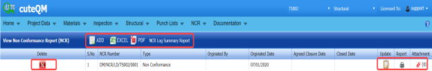
Figure 6.39: View NCR page

6.39.1 Add an NCR
If you want to add a new NCR, follow the same procedure in the topic, “Add NCR”.
6.39.2 View an NCR Log Summary Report
If you want to view an NCR log summary report, click  provided in the upper side of the View NCR page. See Fig 6.39.
6.39.3 Attach a File into an NCR
If you want to attach any file with an NCR listed in the View NCR page, you can attach the file by using  (Attach icon) in the Attachment column. To know how to attach, follow the procedures given in the topic “Attach a file into P&ID”.
6.39.4 Update an NCR
If you want to update any existing NCR in the View NCR page, click  (Update icon) in the Update column for the respective NCR. Edit the details in the respective box you want.
6.39.5 Export an NCR
You can export a list of NCRs added in the View NCR page in both the pdf and excel formats by using  (PDF button) and
  (Excel button). To know how to export, see the topic, “Export P&ID list”.
6.39.6 Delete an NCR
If you want to delete any existing NCR in the View NCR page, you can use  (Delete icon) provided in the View NCR page. To know how to delete, see the topic, “Delete P&ID”.
6.40 Spools Generate Barcode & QR Code
By using the Spools Generate Barcode & QR Code tab in the Piping menu, you can generate the bar code and QR code for the spools for which you have added.
-
Click Spools Generate Barcode & QR Code in the Piping menu.
The Spools Generate Barcode page opens.

Figure 6.40: Spools Generate Barcode page
-
Select the checkbox of the spool for which you want to generate barcode and QR code.
-
If you want to generate the barcode, click
 (Print Barcode button).
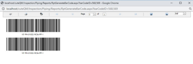
-
If you want to generate the QR code, click
 (Print QR code button).
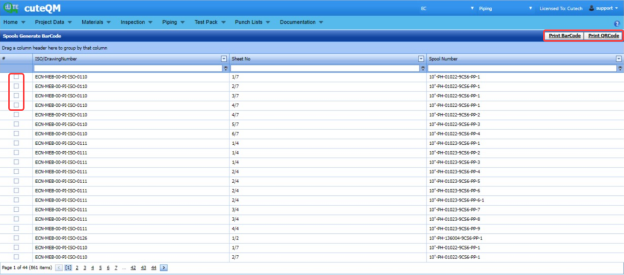


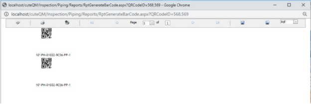
6.41 RT Weekly Report
The RT Weekly Report tab in the Piping menu used to view the week wise RT inspection status. To view the RT inspection status,
- Click RT Weekly Report in the Piping menu.
The RT Weekly Report page opens and shows the RT inspection status.
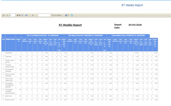

6.42 Weld Summary Sheet
The Weld Summary sheet tab in the Piping menu used you to view a summary report of pipe welding inspection. To view the summary report,
- Click Weld Summary sheet in the Piping menu.
The Piping Weld Inspection Log Sheet page opens.
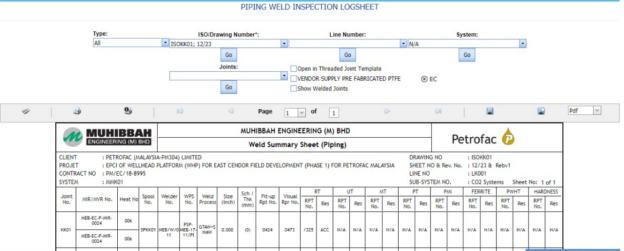
Figure 9.42: Piping Weld Inspection Log Sheet page
- In the Type box, select the type of joint.
-
Do one of the following steps,
-
- In the ISO Drawing Number box, select the isometric drawing number from a drop-down list.
- In the Line Number box, select the line number from a drop-down list.
- In the System box, select the system from a drop-down list.
-
- In the Joints box, select a joint from a list of joints loaded based on the selected ISO.
-
Click Go.
- If you want to open the log sheet in a threaded joint template, click the checkbox of the Open in Threaded Joint Template
- If you want to open the log sheet for Vendor supply pre-fabricated PTFE, click the checkbox of the VENDOR SUPPLY PRE-FABRICATED PTFE
-
The pipe welding inspection log sheet opens for the selected option.


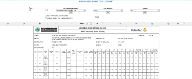
6.42.1 Print a Weld Summary Sheet
If you want to print the weld summary sheet, use  and
and  (print icons) provided in the Weld Summary Sheet page.
- If you want to print the current page of the weld summary sheet, click
 (print icon including the page number).
 - If you want to print all the pages of the weld summary sheet, click
 (print icon).


6.42.2 View a Weld Summary Sheet
You can view the weld summary sheet in various formats by using the option  provided in the upper right corner of the Weld Summary Sheet page.
6.43 Inspection Status Report
Inspection Status Report shows the overall inspection reports such as from fit-up inspection status to NDT inspection status.
If you want to view an inspection status report, do the following steps,
- Click Inspection Status Report in the Piping menu.
The Inspection Status Report page opens.
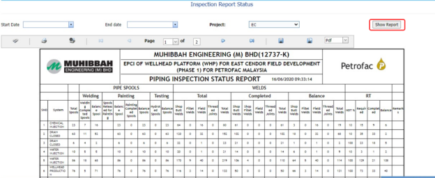
Figure 6.43: Inspection Status Report page
-
In the Start Date and End Date boxes, select the start and end dates.
-
In the Project box, select the project from a drop-down list.
-
Click Show Report.
The Inspection Status Report page shows the spool information, RFI fit-up, RFI weld VI, and NDT inspection status.

6.43.1 Print an Inspection Status Report
If you want to print the inspection status report, use  and
and  (print icons) provided in the Inspection Status Report page. See Fig 6.43.
-
If you want to print the current page of the inspection status report, click
 (print icon including the page number).
 - If you want to print all the pages of the inspection status report, click
 (print icon).


6.43.2 Export an Inspection Status Report
You can export the inspection status report in various formats by using the option  provided in the upper right corner of the Inspection Status Report page.
6.44 Surveillance Entry
The Surveillance Entry tab in the Piping menu helps you to add the observation details of various category, which is done by an inspector.
If you want add a surveillance entry, do the following,
-
Click Surveillance Entry in the Piping menu.
The Surveillance page opens.

Figure 6.44: Surveillance page
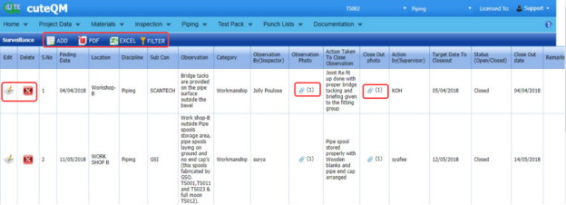
6.44.1 Add a Surveillance Entry
If you want to add a surveillance entry, do the following,
-
Click
 (ADD button) in the Surveillance page. See Fig 6.44.
A new window opens to add a surveillance entry.

 Note: The fields notified with a symbol (*) are mandatory. You must enter the relevant details in that fields before saving.
 - In the Surveillance Date box, select the surveillance date.
-
In the Category box, select a surveillance category from a drop-down list.
-
In the Location box, select a location where the surveillance has done.
-
In the Sub Contractor box, select the sub-contractor from a drop-down list.
- In the Observation By Inspector box, enter the name of the inspector who has done the observation.
-
In the Action by (Supervisor) box, enter the name of the supervisor who has done the action.
-
In the Target Date to Close out box, select the target date to close out the observation.
-
In the Remarks box, enter your remarks if any.
-
In the Observation box, enter the observation’s description.
-
In the Action Taken To Close Observation box, enter the actions to close out the observation.
- In the Status box, select the status Open or Close based on the observation.
-
Click Save.

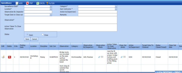

The surveillance entry is successfully added.
6.44.2 Attach a File into a Surveillance Entry
If you want to attach any file with the surveillance entry listed in the Surveillance page, you can attach the file by using  (Attach icon) in the Attachment column. To know how to attach, follow the procedures given in the topic “Attach a file into P&ID”.
6.44.3 Edit a Surveillance Entry
If you want to edit any existing surveillance entry in the Surveillance page, do the following,
- Click
 (Edit icon) in the Edit column for the respective surveillance entry. See Fig 6.44.
 - Click any box where you want to edit the details, and then edit the details in the respective box.
-
Click Save.

6.44.4 Delete a Surveillance Entry
If you want to delete any from the list, you can use (Delete icon) provided in the Delete column of the Surveillance page, See Fig 6.44. To know how to delete, see the topic, “Delete P&ID”.
6.44.5 Export a Surveillance Entry
You can export a list of surveillance entry added in the Surveillance page in the pdf and excel formats by using  (PDF button) and
  (Excel button). To know how to export, see the topic, “Export P&ID list”.
6.44.6 Filter a Surveillance Entry
If you want to filter any surveillance entry from the list in the Surveillance page, you can use  (FILTER button) located on the Surveillance page. To know how to filter, see the topic, “Filter P&ID”.
6.45 Surveillance Report
Once you have added the surveillance entry by using the Surveillance Entry tab, you can view a surveillance report by using the Surveillance Report tab in the Piping menu. If you want to view a surveillance report, do the following steps,
- Click Surveillance Report in the Piping menu.
The Surveillance Report page opens.
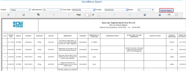
Figure 6.45: Surveillance Report page
-
In the Project box, select a project from a drop-down list.
-
In the Subcontractor box, select a sub-contractor from a drop-down list.
-
In the From Date and To Date boxes, select the from and to dates in respectively.
-
In the Status box, select the status from a drop-down list.
-
Click Preview Report.
The surveillance report will be displayed for the selected dates and status.

6.45.1 Print a Surveillance Report
If you want to print a surveillance report, use  and
and  (print icons) provided in the Surveillance Report page. See Fig 6.45.
-
If you want to print the current page of the surveillance report, click
 (print icon including the page number).
 -
If you want to print all the pages of the surveillance report, click
 (print icon).


6.45.2 Export a Surveillance Report
You can export the surveillance report in various formats by using the option  provided in the upper right corner of the Surveillance Report page.
6.46 Surveillance Category Report
The Surveillance Categories Report tab in the Piping menu shows the surveillance report based on the category wise status.
-
Click Surveillance Categories Report in the Piping menu.
The Surveillance Category Wise Status Report page opens.
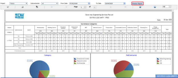
Figure 6.46: Surveillance Report page
-
In the Project box, select a project from a drop-down list.
-
In the Subcontractor box, select a sub-contractor from a drop-down list.
-
In the From Date and To Date boxes, select the from and to dates in respectively.
-
In the Status box, select the status from a drop-down list.
-
Click Preview Report.

The surveillance report will be displayed based on the category wise status.
6.46.1 Print a Surveillance Category Wise Status Report
If you want to print a surveillance report, use  and
and  (print icons) provided in the Surveillance Category Wise Status Report page. See Fig 6.46.
- If you want to print the current page of the surveillance report, click
 (print icon including the page number).
 -
If you want to print all the pages of the surveillance report, click
 (print icon).


6.46.2 Export a Surveillance Category Wise Status Report
You can export the surveillance report in various formats by using the option  provided in the upper right corner of the Surveillance Category Wise Status Report page.
6.47 Blasting and Painting View
The Blasting and Painting View tab in the Piping menu used to add the blasting and painting inspection report.
-
Click Blasting and Painting View in the Piping menu.
The Blasting and Painting page opens.
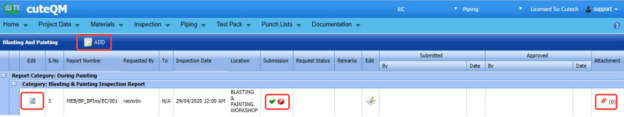
Figure 6.47: Blasting and Painting page

6.47.1 Add a Blasting and Painting Report
If you want to add a blasting and painting report, do the following steps,
-
Click
 (ADD button) in the Blasting and Painting page. See Fig 6.47.
The page opens a new window to add the details of the blasting and painting report.

-
In the Requested by box, enter the name of a person who has requested the blasting and painting report.
-
In the Requested To box, enter the name of a person for whom you want to send the blasting and painting report.
- In the Description / Spec,Ref.No box, select the specification report number.
- In the Inspection Date & Time box, select the inspection date and time.
-
In the Location box, select the inspection location.
-
In the Requisition box, enter the requisition detail.
-
In the System box, select the system.
-
In the Report Type field, select the report type which you want to create.
Before saving the added request, you must add the spools.
 Note: You can add multiple spools for one request.
The page shows a list of spools. If you want to add spools for the request, do the following steps,
-
Click
 (Add icon) of the respective spools you want to add.
The added spools will be moved and listed in the right side of the page.
-
Click Save NDT Request.
The added report will be listed in the Blasting and Painting page.

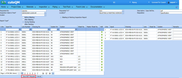


6.47.2 Edit a Blasting and Painting Report
If you want to edit any existing blasting and painting report in the Blasting and Painting page, do the following steps,
- Click
 (Edit icon) in the Edit column for the respective blasting and painting See Fig 6.47.
The Blasting and Painting page opens with the details of the selected blasting and painting report.
- Click any box where you want to edit the details, and then edit the details in the respective box.
-
Click Save.

6.47.3 Submit and Approve a Blasting and Painting Report
Once you have added the blasting and painting report, the Submission column in the Blasting and Painting page is appeared with  (Submit and Reject icons).
- If you want to submit the blasting and painting report, click
 (Submit icon) in the Submission Otherwise click
 (Reject icon) to reject the request.
Once you have submitted the blasting and painting report, the Request Status column in the Blasting and Painting page is appeared with
 (Approve and Reject icons).
 - If you want to approve the blasting and painting report, click
 (Approve icon) in the Request Status Otherwise click
 (Reject icon) to reject the request.


6.47.4 Attach a File into a Blasting and Painting Report
If you want to attach a file with any existing blasting and painting report listed in the Blasting and Painting page, you can attach the file by using  (Attach icon) in the Attachment column. To know how to attach, follow the procedures given in the topic “Attach a file into P&ID”.
6.48 NDT Summary Report
The NDT Summary Report tab in the Piping menu shows the summary report of the NDT inspection.
- Click NDT Summary Report in the Piping menu.
The NDT Summary Report page opens.
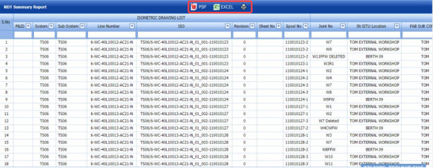
Figure 6.48: NDT Summary Report page

6.48.1 Print an NDT Summary Report
If you want to print an NDT summary report, click  (print icon) provided in the upper side of the NDT Summary Report page. See Fig 6.48.
6.48.2 Export an NDT Summary Report
You can export a list of NDT summary report added in the NDT Summary Report page in the pdf and excel formats by using (PDF button) and
  (Excel button). To know how to export, see the topic, “Export P&ID list”.
6.49 Component Summary Report
Component Summary Report shows the component summary details. If you want to view a component summary report, do the following steps,
- Click Component Summary Report in the Piping menu.
The Component Summary Report page opens.
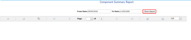
Figure 6.49: Component Summary Report page
- In the From Date and To Date boxes, select the from and to dates in respectively.
-
Click Show Report.
The component summary report opens for the selected dates.

6.49.1 Print a Component Summary Report
If you want to print a component summary report, use  and
and  (print icons) provided in the Component Summary Report page. See Fig 6.49.
- If you want to print the current page of the component summary report, click
 (print icon including the page number).
 - If you want to print all the pages of the component summary report, click
 (print icon).


6.49.2 Export a Component Summary Report
You can export the component summary report in various formats by using the option  provided in the upper right corner of the Component Summary Report page.
6.50 NDT Performance Report (RT & UT)
NDT Performance Report shows the performance details of RT and UT. If you want to view an NDT performance report, do the following steps,
- Click NDT Performance Report in the Piping menu.
The NDT Performance Report page opens.
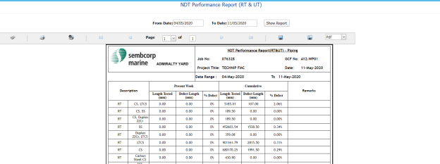
Figure 6.50: NDT Performance Report page
-
In the From Date and To Date boxes, select the from and to dates in respectively.
-
Click Show Report.
The NDT performance report opens for the selected dates.

6.50.1 Print an NDT Performance Report
If you want to print an NDT performance report, use  and
and  (print icons) provided in the NDT Performance Report page. See Fig 6.50.
- If you want to print the current page of the NDT performance report, click
 (print icon including the page number).
 -
If you want to print all the pages of the NDT performance report, click
 (print icon).


6.50.2 Export NDT Performance Report
You can export the NDT performance report in various formats by using the option  provided in the upper right corner of the NDT Performance Report page.
6.51 Pipe Flushing Check List
The Pipe Flushing Check List tab in the Piping menu used to add the pipe flushing check list detail.
- Click Pipe Flushing Check List in the Piping menu.
-
The Pipe Flushing Check List page opens.
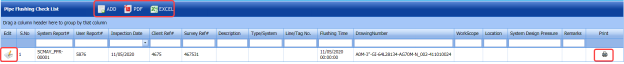
Figure 6.51: Pipe Flushing Check List page
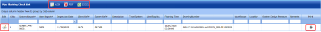
6.51.1 Add a Pipe Flushing Check List
- Click
 (ADD button) in the Pipe Flushing Check List See Fig 6.51.
A new window opens to add a pipe flushing check list.
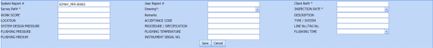
 Note: The fields notified with a symbol (*) are mandatory. You must enter the relevant details in that fields before saving.
 -
In the User Report box, enter the user report number.
-
In the Client Ref box, enter the client reference number.
-
In the Survey Ref box, enter the survey reference number.
-
In the Drawing box, select a drawing number.
-
In the Inspection Date box, select the inspection date.
-
In the Work Scope box, enter the work scope detail.
-
In the Remarks box, enter your remarks if any.
-
In the Description box, enter the description for check list.
-
In the Location box, enter the name of a location.
-
In the Acceptance Code box, enter the acceptance code.
-
In the Flushing Pressure box, enter the flushing pressure value.
-
In the Flushing Temperature box, enter the flushing temperature value.
-
In the Flushing Time box, select the flushing time.
-
In the Flushing Medium box, enter the flushing medium name.
-
In the Instrument Serial No box, enter the instrument serial number.
-
Click Save.


The pipe flushing checklist is successfully added.
6.51.2 Edit a Pipe Flushing Check List
If you want to edit any existing pipe flushing check list in the Pipe Flushing Check List page, do the following steps,
- Click
 (Edit icon) in the Edit column for the respective pipe flushing check list. See Fig 6.51.
A new window opens with the added details of the pipe flushing check list.
-
Click any box where you want to edit the details, and then edit the details in the respective box.
-
Click Save.

6.51.3 Export a Pipe Flushing Check List
You can export a list of pipe flushing check list added in the Pipe Flushing Check List page in the pdf and excel formats by using  (PDF button) and
  (Excel button). To know how to export, see the topic, “Export P&ID list”.
6.51.4 Filter a Pipe Flushing Check List
If you want to filter any pipe flushing check list, you can use (FILTER button) in the Pipe Flushing Check List page. To know how to filter, see the topic, “Filter P&ID”.
6.51.5 Print a Pipe Flushing Check List
If you want to print a pipe flushing check list, click (print icon) provided in the Print column of the Pipe Flushing Check List page. See Fig 6.51.
6.52 Pipe Inspection Check List
The Pipe Inspection Check List tab in the Piping menu used to add the pipe inspection check list detail.
-
Click Pipe Inspection Check List in the Piping menu.
The Pipe Inspection Check List page opens.
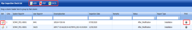
Figure 6.52: Pipe Inspection Check List page

6.52.1 Add a Pipe Inspection Check List
-
Click
 (ADD button) in the Pipe Inspection Check List page. See Fig 6.52.
A new window opens to add a pipe inspection check list.

 Note: The fields notified with a symbol (*) are mandatory. You must enter the relevant details in that fields before saving.
 -
In the User Report Number box, enter the user report number.
-
In the Drawing box, select a drawing number.
-
In the Date box, select the inspection date.
-
In the Remarks box, enter your remarks if any.
-
In the Status field, select the status of the check list.
-
In the Report Type box, select the report type of the check list.
-
Click Save.

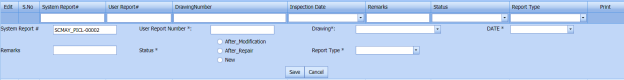

The pipe inspection checklist is successfully added.
6.52.2 Edit a Pipe Inspection Check List
If you want to edit any existing pipe inspection check list in the Pipe Inspection Check List page, do the following steps,
- Click
 (Edit icon) in the Edit column for the respective pipe inspection check list. See Fig 6.52.
A new window opens with the added details of the pipe inspection check list.
-
Click any box where you want to edit the details, and then edit the details in the respective box.
-
Click Save.

6.52.3 Export a Pipe Inspection Check List
You can export a list of pipe inspection check list added in the Pipe Inspection Check List page in the pdf and excel formats by using  (PDF button) and
  (Excel button). To know how to export, see the topic, “Export P&ID list”.
6.52.4 Filter a Pipe Inspection Check List
If you want to filter any pipe inspection check list, you can use  (FILTER button) in the Pipe Inspection Check List page. To know how to filter, see the topic, “Filter P&ID”.
6.52.5 Print a Pipe Inspection Check List
If you want to print a pipe Inspection check list, click (print icon) provided in the Print column of the Pipe Inspection Check List page. See Fig 6.52.
6.53 Warning Letter
The Warning Letter Report tab in the Piping menu helps you to add a warning letter that addresses the performance issue of a worker. The warning letter explains about the mistakes done by the worker. If you want to add a warning letter against any worker, do the following,
- Click Warning Letter in the Piping menu.
The Warning Letter Report page opens.
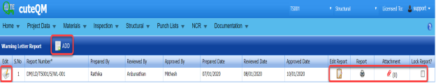
Figure 6.53: Warning Letter Report page

6.53.1 Add a Warning Letter Report
If you want to add a warning letter report,
- Click
 (ADD button) in the Warning Letter Report See Fig 6.53.
A new window opens to add a warning letter report.
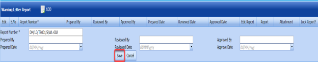
 Tip: A report number for a new warning letter report will be updated automatically in the Report Number box.
 - In the Prepared By box, enter the name a person who has prepared the warning letter report.
-
In the Prepared Date box, enter the prepared date of the warning letter report.
-
In the Reviewed By box, enter the name a person who has reviewed the warning letter report.
-
In the Reviewed Date box, enter the reviewed date of the warning letter report.
-
In the Approved By box, enter the name a person who has approved the warning letter report.
-
In the Approved Date box, enter the approved date of the warning letter report.
-
Click Save.


The warning letter report is successfully added. Once you have added the warning letter report, you must add the warning letter details.
6.53.2 Add Warning Letter Details
- Click
 (Edit icon) in the Edit Report column of the Warning Letter Report page. See Fig 6.53.
The Warning Letter Details window opens including a default warning letter template.

-
In the Date box, select the date of issuing the warning letter.
-
In the From box, enter the name of a person who issues the warning letter.
-
In the To box, enter the name of a person who receives the warning letter.
-
In the Attention box, enter the relevant detail.
-
In the Subject box, enter the subject of this warning letter.
-
In the Remarks box, enter your remarks if any.
-
In the Content box, if you want to change any information given in the template, you can change.
-
Click Save Details.

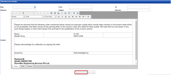
6.53.3 Print a Warning Letter Report
If you want to print a warning letter report, click  (print icon) provided in the Report column of the Warning Letter Report page. See Fig 6.53.
 Tip: If you want to lock any warning letter report, click the check box provided in the Lock Report? column of the Warning Letter Report page. See Fig 6.53.
6.53.4 Attach a File into a Warning Letter Report
If you want to attach any file with any warning letter report listed in the Warning Letter Report page. To know how to attach, follow the procedures given in the topic “Attach a file into P&ID”.
6.54 Welder Performance Summary
The Welder Performance Summary tab in the Piping menu used to add welder performance record. To add the welder performance record,
- Click Welder Performance Summary in the Piping menu.
The Welder Performance Record page opens.
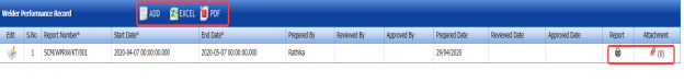
Figure 6.54: Welder Performance Record page

6.54.1 Add a Welder Performance Record
- Click
 (ADD button) in the Welder Performance Record See Fig 6.54.
A new window opens to add a welder performance record.

 Note: The fields notified with a symbol (*) are mandatory. You must enter the relevant details in that fields before saving.
 - In the Start Date and End Date boxes, select the start and end dates.
-
In the Prepared By box, enter the name a person who has prepared the welder performance record.
-
In the Prepared Date box, enter the prepared date of the welder performance record.
-
In the Reviewed By box, enter the name a person who has reviewed the welder performance record.
-
In the Reviewed Date box, enter the reviewed date of the welder performance record.
-
In the Approved By box, enter the name a person who has approved the welder performance record.
-
In the Approved Date box, enter the approved date of the welder performance record.
-
Click Save.

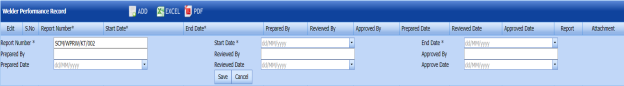

The welder performance record is successfully added.
6.54.2 Edit a Welder Performance Record
If you want to edit any existing welder performance record in the Welder Performance Record page, do the following steps,
- Click
 (Edit icon) in the Edit column for the respective welder performance record. See Fig 6.54.
A new window opens with the added details of the welder performance record.
- Click any box where you want to edit the details, and then edit the details in the respective box.
-
Click Save.

6.54.3 Export a Welder Performance Record
You can export a list of welder performance records added in the Welder Performance Record page in the pdf and excel formats by using  (PDF button) and
  (Excel button). To know how to export, see the topic, “Export P&ID list”.
6.54.4 Filter a Welder Performance Record
If you want to filter any welder performance record, you can use  (FILTER button) in the Welder Performance Record page. To know how to filter, see the topic, “Filter P&ID”.
6.54.5 Print a Welder Performance Record
If you want to print a welder performance record, click  (print icon) provided in the Print column of the Welder Performance Record page. See Fig 6.54.
6.54.5 Attach a File into a Welder Performance Record
If you want to attach a file with any existing welder performance record listed in the Welder Performance Record page, you can attach the file by using (Attach icon) in the Attachment column. To know how to attach, follow the procedures given in the topic “Attach a file into P&ID”.
6.55 Weld Repair Log Report
Weld Repair Log Report shows the weld repair log details. If you want to view a weld repair log report, do the following steps,
-
Click Weld Repair Log Report in the Piping menu.
The Weld Repair Log Report page opens.
Figure 6.55: Weld Repair Log Report page

6.55.1 Print a Weld Repair Log Report
If you want to print a weld repair log report, use  and
and  (print icons) provided in the Weld Repair Log Report page. See Fig 6.55.
- If you want to print the current page of the weld repair log report, click
 (print icon including the page number).
 -
If you want to print all the pages of the weld repair log report, click
 (print icon).


6.55.2 Export a Weld Repair Log Report
You can export the weld repair log report in various formats by using the option provided in the upper right corner of the Weld Repair Log Report page.
6.56 AFI Report Status
The AFI Report Status tab in the Piping menu shows the AFI report status.
- Click AFI Report Status in the Piping menu.
The AFI Report Status page opens.

Figure 6.56: AFI Report Status page
-
In the Project box, select a project from a drop-down list.
-
In the Category box, select a category from a drop-down list.
-
In the From Date and To Date boxes, select the from and to dates in respectively.
-
Click Show Report.
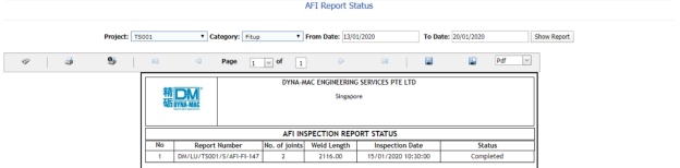
The AFI report status will be displayed.
6.56.1 Print an AFI Report Status
If you want to print an AFI report status, use  and
and  (print icons) provided in the AFI Report Status page. See Fig 6.56.
- If you want to print the current page of the AFI report status, click
 (print icon including the page number).
 -
If you want to print all the pages of the AFI report status, click
 (print icon).


6.56.2 Export an AFI Report Status
You can export the AFI report status in various formats by using the option provided in the upper right corner of the AFI Report Status page.
6.57 Status by ISO for NDT Requirement
The Status by ISO for NDT Requirement tab in the Piping menu used to view the ISO status for NDT requirement.
- Click Status by ISO for NDT Requirement in the Piping menu.
The page shows the status by ISO for NDT requirement.

Figure 6.57: Status by ISO for NDT Requirement page
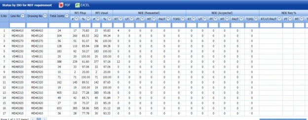
6.57.1 Export Status by ISO for NDT Requirement
You can export the status in the Status by ISO for NDT Requirement page in the pdf and excel formats by using (PDF button) and (Excel button). To know how to export, see the topic, “Export P&ID list”.
6.58 Piping Widget
The Piping Widget tab in the Piping menu used to view overall summary of the piping NDT, NDT number of joint status, and overall welder rejected status.
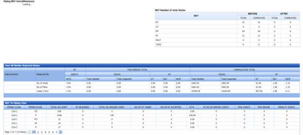
6.59 Welder Not Welded List
The Welder Not Welded List tab in the Piping menu used to view the list of welders who has not performing the welding work for more than 15 days. If you want to view the welder list,
- Click Welder Not Welded List in the Piping menu.
The Welder Recently Not Welded List page shows a list of welders including their NRIC and welder numbers, last weld date, and no of days not performing welding.
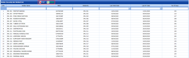
Figure 6.59: Welder Recently Not Welded List page
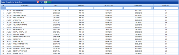
6.59.1 Export Welder Not Welded List
You can export the welder list in the Welder Recently Not Welded List page in the pdf and excel formats by using  (PDF button) and (Excel button). To know how to export, see the topic, “Export P&ID list”.
6.60 Daily Piping Production Log Report
The Daily Piping Production Log Report tab in the Piping menu used to view the production details in the piping project on a daily basis. If you want to view the production log report,
- Click Daily Piping Production Log Report in the Piping menu.
The Daily Piping Production Log Report page shows production details in the piping project on a daily basis.
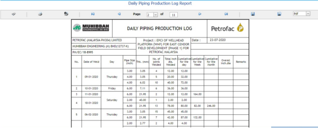
Figure 6.60: Daily Piping Production Log Report page

6.60.1 Print a Daily Piping Production Log Report
If you want to print a daily piping production log report, use  and
and  (print icons) provided in the Daily Piping Production Log Report page. See Fig 6.60.
- If you want to print the current page of the daily piping production log report, click
 (print icon including the page number).
 -
If you want to print all the pages of the daily piping production log report, click
 (print icon).


6.60.2 Export a Daily Piping Production Log Report
You can export the daily piping production log report in various formats by using the option  provided in the upper right corner of the Daily Piping Production Log Report page.
6.61 RFI Log Report
6.62 NDT Log Report
The NDT Log Report tab in the Piping menu used to view the NDT log report. If you want to view the NDT log report,
- Click NDT Log Report in the Piping menu.
The NDT Log Report page shows NDT log report.
- In the From Date and To Date boxes, select the from and to dates.
-
Click Load Report.
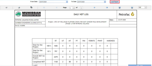
Figure 6.62: NDT Log Report page
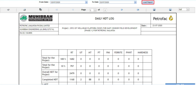
6.62.1 Print an NDT Log Report
If you want to print an NDT log report, use  and
and  (print icons) provided in the NDT Log Report page. See Fig 6.62.
- If you want to print the current page of the NDT log report, click
 (print icon including the page number).
 -
If you want to print all the pages of the NDT log report, click
 (print icon).


6.62.2 Export an NDT Log Report
You can export the NDT log report in various formats by using the option  provided in the upper right corner of the NDT Log Report page.
6.63 DB Summary Report
The DB Summary Report tab in the Piping menu used to view the DB summary report. If you want to view the DB summary report,
- Click DB Summary Report in the Piping menu.
The Total Piping DB Summary page shows the DB summary report.

Figure 6.63: Total Piping DB Summary page
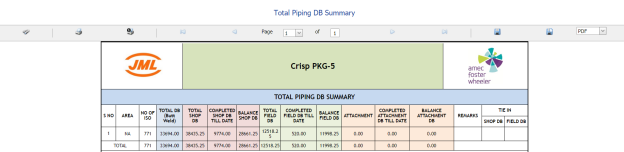
6.63.1 Print a DB Summary Report
If you want to print a DB summary report, use  and
and  (print icons) provided in the Total Piping DB Summary page. See Fig 6.63.
- If you want to print the current page of the DB summary report, click
 (print icon including the page number).
 - If you want to print all the pages of the DB summary report, click
 (print icon).


6.63.2 Export a DB Summary Report
You can export the DB summary report in various formats by using the option  provided in the upper right corner of the Total Piping DB Summary page.
6.64 Weld Repair Report
Weld Repair Report shows the weld repair details. If you want to view a weld repair report, do the following steps,
-
Click Weld Repair Report in the Piping menu.
The Weld Repair Report page opens.
- In the Repair No box, select the repair number.
- In the ISO/Drawing Number box, select the ISO drawing number.
-
Click Go.
The weld repair details open for the selected repair number.

Figure 6.64: Weld Repair Report page
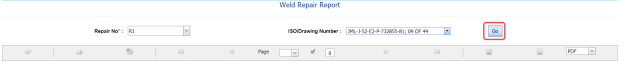
6.64.1 Print a Weld Repair Report
If you want to print a weld repair report, use  and
and  (print icons) provided in the Weld Repair Report page. See Fig 6.64.
- If you want to print the current page of the weld repair report, click
 (print icon including the page number).
 - If you want to print all the pages of the weld repair report, click
 (print icon).


6.64.2 Export a Weld Repair Report
You can export the weld repair report in various formats by using the option  provided in the upper right corner of the Weld Repair Report page.
6.65 Pending NDT Log Report
Pending NDT Log Report shows the pending NDT log details. If you want to view the pending NDT log report, do the following steps,
- Click Pending NDT Log Report in the Piping menu.
The Pending NDT Log page opens.
-
In the ISO/Drawing Number box, select the ISO drawing number.
-
Click Show Report.
The pending NDT log details open for the selected ISO drawing number.

Figure 6.65: Pending NDT Log page
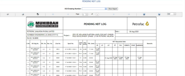
6.65.1 Print a Pending NDT Log Report
If you want to print a pending NDT log report, use  and
and  (print icons) provided in the Pending NDT Log page. See Fig 6.65.
- If you want to print the current page of the pending NDT log report, click
 (print icon including the page number).
 -
If you want to print all the pages of the pending NDT log report, click
 (print icon).


6.65.2 Export a Pending NDT Log Report
You can export the pending NDT log report in various formats by using the option  provided in the upper right corner of the Pending NDT Log page.
6.66 RT Films Status Report
The RT Film Status Report tab in the Piping menu used to view the RT film status. If you want to view the RT film status report,
- Click RT Film Status Report in the Piping menu.
The RT Film Report page shows the RT film status.
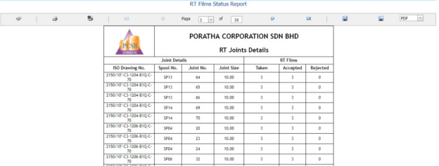
Figure 6.66: RT Film Status Report page

6.66.1 Print an RT Film Status Report
If you want to print an RT film status report, use  and
and  (print icons) provided in the RT Film Status Report page. See Fig 6.66.
- If you want to print the current page of the RT film status report, click
 (print icon including the page number).
 - If you want to print all the pages of the RT film status report, click
 (print icon).


6.66.2 Export an RT Film Status Report
You can export the RT film status report in various formats by using the option  provided in the upper right corner of the RT Film Status Report page.
Test Pack (ISO)
7.1 Test Pack (ISO)
The Test Pack (ISO) tab in the Test Pack menu helps you to add a test back (ISO). To navigate to the test pack adding page,
- Click Test Pack (ISO) in the Test Pack menu. The Test Pack page opens.

Figure 7.1: Test Pack (ISO) page
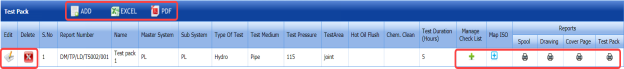
7.1.1 Add a Test Pack
If you want to add a test pack, do the following steps,
-
Click
 (ADD button) in the Test Pack page. See Fig 7.1.
The page opens a new window to add the details of a test pack.

 Note: The field notified with a symbol (*) is mandatory. You must enter the relevant details in that fields before saving.
 Tip: A report number for a new test pack will be updated automatically in the Report Number box. If you want to change the report number, you can change.
 -
In the System box, select a system from a drop-down list.
-
In the Name box, enter the name of the test pack.
-
In the Sub System box, select a sub system from a drop-down list.
-
In the Type of Test box, enter the type of test.
-
In the Test Medium box, enter the name of a test medium.
-
In the Test Pressure box, enter the test pressure value.
-
In the Test Area box, enter the name of a test area.
-
In the Hot Oil Flush box, enter the detail of hot oil flush.
-
In the Chem. Clean box, enter the detail of chemical cleaning.
-
In the Test Duration (Hours) box, enter the duration of test.
-
Click Save.
The test pack is successfully added and listed in the Test Pack page. Once you have added a test pack, you can manage the checklist of MCR and map ISO drawings/spool for the added test pack.

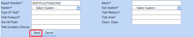


7.1.2 Manage a Checklist
If you want to manage the checklist of test pack,
- Click (Add icon) in the Manage Checklist See Fig 7.1.
The page redirects you to the Checklist Name page.

-
Click
 (ADD button) in the Checklist Name page.
The page opens a new window to add the details of the checklist.
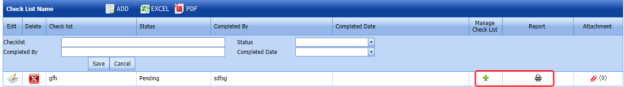
-
In the Checklist box, enter the checklist name.
-
In the Status box, select the status of the checklist.
-
In the Completed by box, enter the name of a person who has completed checklist.
-
In the Completed Date box, select the completed date of the checklist.
-
Click Save.
The added checklist will be listed in the Checklist Name page.
- If you want to manage the added checklist, click (Add icon) in the Manage Checklist column of the Checklist Name page.
The MCR Checklist page opens for the selected checklist.
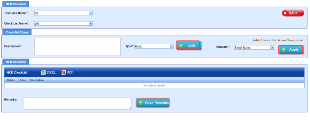
-
In the Description box, enter the description for the checklist you want to add.
- In the Type box, select the checklist type and click
 .
.
The added checklist will be listed in the MCR Checklist window.
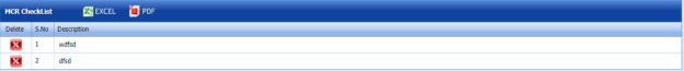
- If you want to add the checklists from a template, in the Template box, select the template from a drop-down list and click
 .
.
The checklists in the template will be listed in the MCR Checklist window.
-
In the Remarks box, enter your remarks.
-
Click
 .
.


7.1.3 Map ISO
If you want to map ISO drawings/ spool for the added test pack, do the following steps,
- Click
 (Add icon) in the Map ISO column of the respective test pack.
The Map Drawings/Spool window opens.

- Click
 (ADD button) in the Map Drawings/Spool window.
The window shows a list of drawing and their spools.
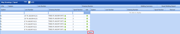
- Do one of the following steps to add spools,
-
-
If you want to add a spool, click
 (Add icon) provided in the Add column.
The added spools will be moved to right side of the window.
- If you want to add all spools in the drawing, click
 (Add icon) provided in the Drawing Number column.
The added spools will be moved to right side of the window.
-
-
-
Click Save.
The added spools will be listed in the in the Map Drawings/Spool window.
-
-
If you want to view a weld inspection summary report, click
 (print icon) provided in the Welding Summary column.
 -
If you want to view a visual welding report, click
 (print icon) provided in the Visual Welding Report column.
-
-

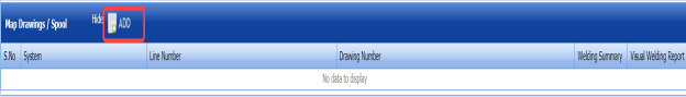


7.1.4 Edit a Test Pack
If you want to edit any added test pack in the Test Pack page,
- Click
 (Edit icon) of the respective test pack. See Fig 7.1.
The Test Pack page shows the details of the selected test pack.
-
Edit the details where you want.
-
Click Save.

7.1.5 Delete a Test Pack
If you want to delete any existing test pack in the Test Pack page, you can use  (Delete icon) provided in the Test Pack page. To know how to delete, see the topic, “Delete P&ID”.
7.1.6 View a Test Pack Spool List Report
If you want to view a test pack spool list report, click  (print icon) provided in the Spool column.
7.1.7 View a Drawing List Report
If you want to view a drawing list report, click (print icon) provided in the Drawing column.
7.1.8 View a Cover Page of Test Pack
If you want to view a cover page of test pack, click  (print icon) provided in the Cover Page column.
7.1.9 View a Test Pack Report
If you want to view a test pack report, click  (print icon) provided in the Test Pack column.
7.1.10 Export Test Pack list
You can export a list of test packs added in the Test Pack page in both the pdf and excel formats by using  (PDF button) and
  (Excel button). To know how to export, see the topic, “Export P&ID list”.
7.2 Test Pack (Spool)
The Test Pack (Spool) tab in the Test Pack menu helps you to add a test back (Spool). To navigate to the test pack adding page,
- Click Test Pack (Spool) in the Test Pack menu.
The Test Pack page opens.

Figure 7.2: Test Pack page
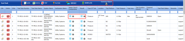
7.2.1 Add a Test Pack
If you want to add a test pack, do the following steps,
- Click
 (ADD button) in the Test Pack See Fig 7.2.
The page opens a new window to add the details of a test pack.
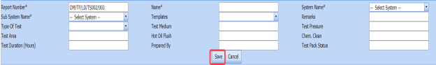
 Note: The field notified with a symbol (*) is mandatory. You must enter the relevant details in that fields before saving.
 Tip: A report number for a new test pack will be updated automatically in the Report Number box. If you want to change the report number, you can change.
 -
In the System Name box, select a system from a drop-down list.
-
In the Name box, enter the name of the test pack.
-
In the Sub System Name box, select a sub system from a drop-down list.
-
In the Type of Test box, enter the type of test.
-
In the Templates box, select a template from a drop-down list.
-
In the Remarks box, enter your remarks if any.
-
In the Test Medium box, enter the name of a test medium.
-
In the Test Pressure box, enter the test pressure value.
-
In the Test Area box, enter the name of a test area.
-
In the Hot Oil Flush box, enter the detail of hot oil flush.
-
In the Chem. Clean box, enter the detail of chemical cleaning.
-
In the Test Duration (Hours) box, enter the duration of test.
-
In the Prepared By box, enter the name of a person who has prepared the test pack.
-
In the Test Pack Status box, enter the status of the test pack.
-
Click Save.
The test pack is successfully added and listed in the Test Pack page. Once you have added a test pack, you can manage the checklist and assign spools and components for the added test pack.
 Note: If you want to perform the above tasks, click
  (Add icon) in the Assign Spool/ Components column of the respective test pack.
The page shows the Manage Checklist, Assign Spool, and Assign Component options.


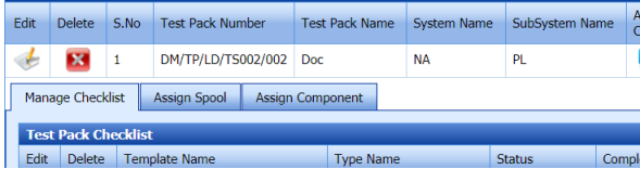
7.2.2 Manage a Checklist
If you want to manage the test pack checklist, Click the Manage Checklist option.
The Test Pack Checklist window opens.

If you want to edit any checklist, you can edit the checklist.
7.2.3 Assign a Spool
If you want to assign spool for the added test pack, do the following steps,
- Select the Assign Spool option.
The Assign Spool window opens.
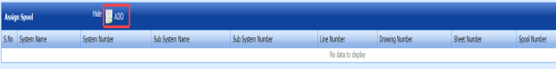
-
Click
 (ADD button) in the Assign Spool window.
The window shows a list of spools.
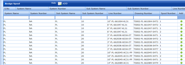
- If you want to add a spool, click
 (Add icon) provided in the Add column.
 -
Click Save.
The added spools will be listed in the in the Assign Spool window.


7.2.4 Assign a Component
If you want to assign a component, click the Assign Component option.
The Assign Component window opens.
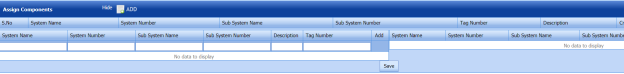
7.2.5 Add Test Pack Result
After completing the spool test for the added test pack request, you can add the result details. To add results, do the following steps,
- Click
 (Add icon) in the Result column of the Test Pack See Fig 7.2.
The Test Package window opens.


The Test Package window contains the following options: Index, Pre-Pressure Checklist, Pressure Test, Final Review, Flushing Test, Content, Work instruction, Pre-Checklist, Punch List, Weld Inspection, Hydro Test Report, Flushing Check, BP Test, Instrument List, and Post Checklist.


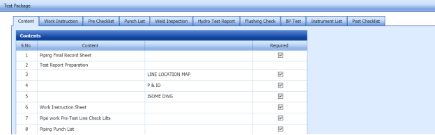
Index
If you want to add index for the test pack,
- Click Index option.
The Index window opens with a list of contents.
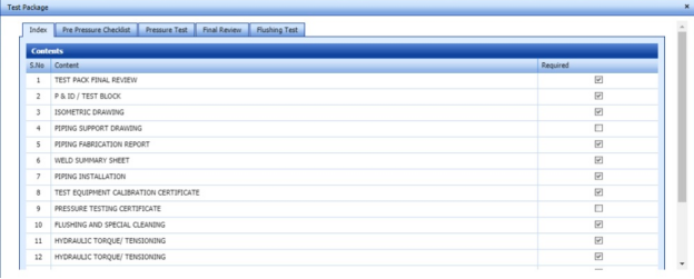
-
Select the contents which you want to add in the Index.

Pre-Pressure Checklist
If you want to add pre-pressure checklist for the test pack,
- Click Pre-Pressure Checklist option.
The Pre-Pressure Checklist window opens with a list of checklists.
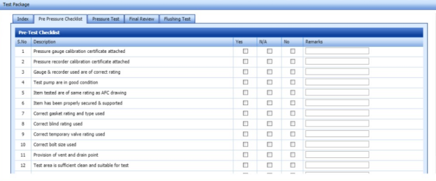
-
Select the checklists which you want to add.
-
-
If you want to add the checklist, select the checkbox in the Yes column for the respect checklist.
- If the checklist is not applicable, select the checkbox in the N/A column.
- If you do not want to any checklist, select the checkbox in the No column for the respect checklist.
-
-

Pressure Test
If you want to add pressure test results,
- Click Pressure Test option.
The Pressure Test window opens with the following boxes: ISO List, Test Description, and Test Equipment.
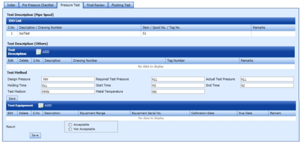
-
In the Test Description box, click
 (ADD button).
The Test Method box opens.
-
-
In the Design Pressure box, enter the design pressure value.
-
In the Required Test Pressure box, enter the required test pressure value.
-
In the Actual Test Pressure box, enter the actual test pressure value.
-
In the Holding Time box, enter the holding time range.
-
In the Start Time box, enter the start time of the pressure test.
-
In the End Time box, enter the end time of the pressure test.
-
In the Test Medium box, enter the test medium name.
- In the Metal Temperature box, enter the metal temperature value.
-
Click Save.
-
-
- In the Result field, select the result of the pressure test whether Acceptable or Not Acceptable.
-
Click Save.


Final Review
If you want to view the final review of the test pack,
- Click Final Review option.
The Final Review window opens with the final review report.
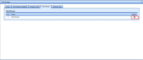
-
If you want to view the final review report, click
 (print icon).


Flushing Test
If you want to add flushing test results,
- Click Flushing Test option.
The Flushing Test window opens with the following boxes: Test Description (Pipe Spool), Test Description, and Test Equipment.
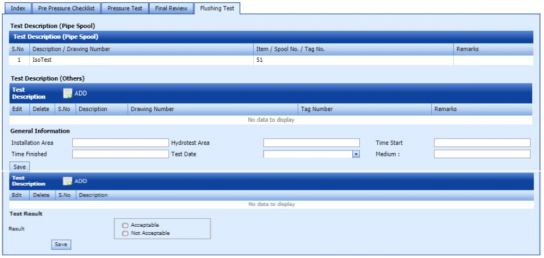
-
In the Test Description (Others) box, click
 (ADD button).
The General Information box opens.
-
-
In the Installation Area box, enter the installation area value.
-
In the Hydrotest Area box, enter the hydrotest area value.
-
In the Start Time box, enter the start time of the flushing test
-
In the Time Finished box, enter the finished time of the flushing test.
-
In the Test Date box, select the date of flushing test.
-
In the Test Medium box, enter the test medium name.
-
Click Save.
-
-
- In the Test Result field, select the result of the pressure test whether Acceptable or Not Acceptable.
-
Click Save.

Content
If you want to add content for the test pack,
-
Click Content option.
The Contents window opens with a list of contents.
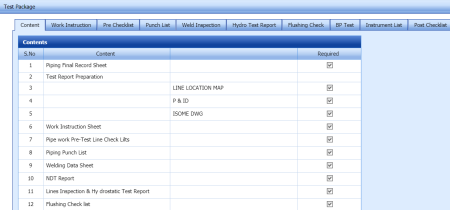
-
Select the contents which you want to add in the Content.

Work Instruction Sheet
If you want to add the work instruction,
- Click Work Instruction Sheet option.
The Work Instruction Sheet window opens.
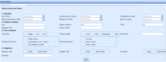
-
In the Schedule field, enter the work schedule details.
-
In the Design Condition field, enter the design condition details.
-
In the Test Condition field, enter the test condition details.
-
In the Judgement field, enter the judgement details.
-
Click Save.

Pre-Test Checklist
If you want to add pre-test checklist for the test pack,
- Click Pre-Test Checklist option.
The Pre-Test Checklist window opens with a list of checklists.
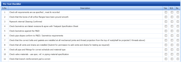
- Select the checklists which you want to add.
-
- If you want to add the checklist, select the checkbox in the Yes column for the respect checklist.
-
If the checklist is not applicable, select the checkbox in the N/A column.
- If you do not want to any checklist, select the checkbox in the No column for the respect checklist.
-

Welding Inspection Record
If you want to view the welding inspection record,
-
Click Welding Inspection Record option.
The Welding Inspection Record window shows the welding inspection record.
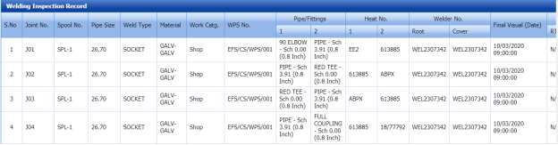

Hydro Test Report
If you want to add the hydro test report,
- Click Hydro Test Report option.
The Hydrostatic Test Report window shows a new window to add the hydrostatic test report details.

-
In the Test Fluid box, enter the test fluid name.
-
In the Type of Test box, enter the test type.
-
In the Test Gauge Range box, enter the test gauge range.
-
In the Test Gauge No box, enter the test gauge number.
-
In the Duration Test Start box, enter the test starting time.
-
In the Duration Test Finish box, enter the test finishing time.
-
In the Date of Test box, select the test date.
-
In the Test Pressure box, enter the test pressure value.
-
In the Actual Pressure box, enter the actual pressure value.
-
Click Save.
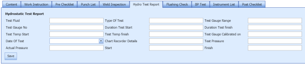
Flushing Check List
If you want to add the flushing check list,
- Click Flushing Check List option.
The Flushing Check List window shows a new window to add the flushing check list details.

-
In the Flushing Circuit No box, enter the flushing circuit number.
-
In the Origin box, enter the origin name.
-
In the Termination box, enter the termination detail.
-
In the Remarks box, enter your remarks if any.
-
Select the appropriate checklist.
-
Click Save.
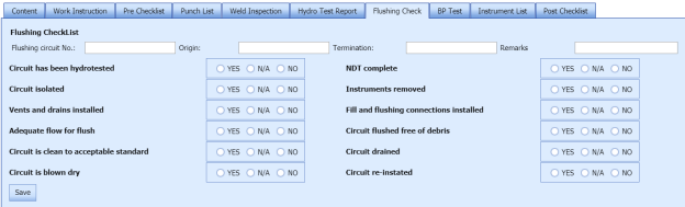
BP List
If you want to add the BP list detail,
- Click BP List option.
The BP List window shows a new window to add the BP list details.
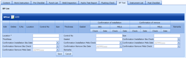
-
Click
 (ADD button) in the BP List window.
 -
In the Location box, enter the location name.
-
In the Control No box, enter the control number.
-
In the Size box, enter the size vale.
-
In the Thickness box, enter the thickness value.
-
In the Gasket box, enter the gasket detail.
-
Click Save.


Instrument List
If you want to add the instrument list detail,
- Click Instrument List option.
The Instrument List window shows a new window to add the instrument list details.
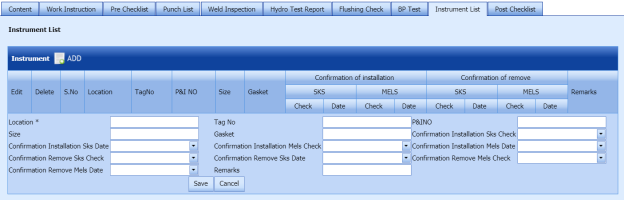
-
Click
 (ADD button) in the Instrument List window.
 -
In the Location box, enter the location name.
-
In the Tag No box, enter the tag number.
-
In the P&I No box, enter the P&I number.
-
In the Size box, enter the size vale.
-
In the Gasket box, enter the gasket detail.
-
In the Remarks box, enter your remarks if any.
-
Click Save.


Post-Test Checklist
If you want to add post-test checklist for the test pack,
- Click Post-Test Checklist option.
The Post-Test Checklist window opens with a list of checklists.

- Select the checklists which you want to add.
-
- If you want to add the checklist, select the checkbox in the Yes column for the respect checklist.
-
If the checklist is not applicable, select the checkbox in the N/A column.
- If you do not want to any checklist, select the checkbox in the No column for the respect checklist.
-
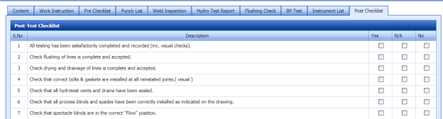
7.2.6 Edit a Test Pack
If you want to edit any added test pack in the Test Pack page,
-
Click
 (Edit icon) of the respective test pack. See Fig 7.2.
The Test Pack page shows the details of the selected test pack.
-
Edit the details where you want.
-
Click Save.

7.2.7 Delete a Test Pack
If you want to delete any existing test pack in the Test Pack page, you can use  (Delete icon) provided in the Test Pack page. To know how to delete, see the topic, “Delete P&ID”.
7.2.8 View a Test Pack MDR Report
If you want to view a test pack MDR report, click  (print icon) provided in the Assign Spool/Components column.
7.2.9 Attach a File into a Test Pack
If you want to attach any file with any test pack listed in the Test Pack page, you can attach the file by using (Attach icon) in the Attachment column. To know how to attach, follow the procedures given in the topic “Attach a file into P&ID”.
7.2.10 Export Test Pack list
You can export a list of test packs added in the Test Pack page in both the pdf and excel formats by using  (PDF button) and
  (Excel button). To know how to export, see the topic, “Export P&ID list”.
7.2.11 Filter a Test Pack
If you want to filter any specific test pack in the Test Pack page, you can use  (FILTER button) located on the Test Pack page. To know how to filter, see the topic, “Filter P&ID”.
7.2.12 Import Multiple Test Packs
If you want to import multiple test packs together, do the following,
- Click
 (TEMPLATE button). See Fig 7.2.
An excel worksheet will be downloaded with a predefined template to enter the details of systems.

-
Enter the required test pack details in the respective columns of the excel worksheet.
- Once you have added the test pack details in the excel worksheet, save the excel worksheet on your computer.
-
Click
 (IMPORT button). See Fig 7.2.
A new window opens for importing the excel worksheet saved on your computer.

-
Click
 (Browse button) to select the excel worksheet to be uploaded.
 -
Select the excel worksheet you want to upload from your computer.
-
Click
 (Upload button) to export the test pack details that are included in the excel worksheet.

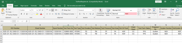


The details of the test packs in the worksheet will be displayed in the Test Pack page.
7.2.13 View a Test Pack Summary Report
If you want to view a test pack summary report, click (Summary Report icon) provided in the Test Pack page.
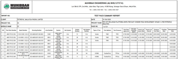
7.3 Test Pack Checklist
The Test Pack Checklist tab in the Test Pack menu helps you add the checklist items for the specific test pack. To add the checklist,
- Click Test Pack Checklist in the Test Pack menu.
The MCR Checklist page opens.

-
In the Test Pack Name box, select the test pack name from a drop-down list.
-
In the Checklist Name box, select a checklist from a drop-down list.
The Checklist Items and MCR Checklist windows open.
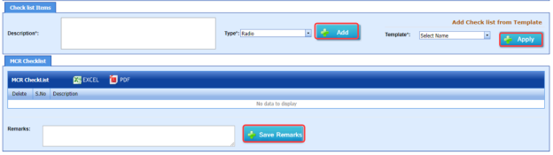
-
In the Description box, enter the description for the checklist you want to add.
-
In the Type box, select the checklist type and click
 .
.The added checklist will be listed in the MCR Checklist window.

- If you want to add the checklists from a template, in the Template box, select the template from a drop-down list and click
 .
.
The checklists in the template will be listed in the MCR Checklist window.
- In the Remarks box, enter your remarks.
-
Click
 .
.
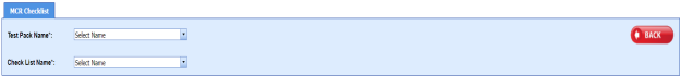


7.4 MCR Checklist Template
The MCR Checklist Template tab in the Test Pack menu helps you to add MC/SC – Check Record (CR)/Check Sheet (CS) templates. To navigate to the templates adding page,
-
Click MCR Checklist Template in the Test Pack menu.
The MC/SC – CR/CS Templates page opens.

Figure 7.4: MC/SC – CR/CS Templates page

7.4.1 Add a CR/CS Template
If you want to add a CR/CS template,
-
Click
 (ADD button) in the MC/SC – CR/CS Templates page. See Fig 7.4.
The page opens a new window to add the details of a test pack.

 Note: The field notified with a symbol (*) is mandatory. You must enter the relevant details in that fields before saving.
 - In the CR/CS Name box, enter the name for CR/CS.
- In the Template Type box, select a template whether CR or CS.
-
In the Description box, enter the description for CR/CS.
-
Click Save.
The template is successfully added and listed in the MC/SC – CR/CS Templates page. Once you have added the template details, you must import the respective template.


7.4.2 Import a CR/CS Template
If you want to import CR/CS template,
- Click
 (Add icon) of the respective CR/CS name in the MC/SC – CR/CS Templates page.
The Check Records window opens.
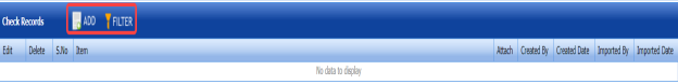
-
Click
 (ADD button) in the Check Records window.
-
In Items box, enter the details of items.
-
Browse and attach a CS/CR template you want to import.
-
Click Save.


7.4.3 Edit a CR/CS Template
If you want to edit any added CR/CS template in the MC/SC – CR/CS Templates page,
- Click
 (Edit icon) of the respective CR/CS template. See Fig 7.4.
The MC/SC – CR/CS Templates page shows the details of the selected CR/CS template.
-
Edit the details where you want.
-
Click Save.

7.4.4 Delete a CR/CS Template
If you want to delete any existing CR/CS template in the MC/SC – CR/CS Templates page, you can use  (Delete icon) provided in the MC/SC – CR/CS Templates page. To know how to delete, see the topic, “Delete P&ID”.
7.4.5 Export CR/CS Template list
You can export a list of CR/CS templates added in the MC/SC – CR/CS Templates page in both the pdf and excel formats by using  (PDF button) and
  (Excel button). To know how to export, see the topic, “Export P&ID list”.
7.4.6 Filter a CR/CS Template
If you want to filter any specific CR/CS template in the MC/SC – CR/CS Templates page, you can use  (FILTER button) located on the Test Pack page. To know how to filter, see the topic, “Filter P&ID”.
7.4.7 Import Multiple CR/CS Templates
If you want to import multiple CR/CS templates together, do the following,
- Click
 (TEMPLATE button). See Fig 7.4.
An excel worksheet will be downloaded with a predefined template to enter the details of CR/CS templates.

-
Enter the required CR/CS template details in the respective columns of the excel worksheet.
- Once you have added the CR/CS template details in the excel worksheet, save the excel worksheet on your computer.
- Click
 (IMPORT button). See Fig 7.4.
A new window opens for importing the excel worksheet saved on your computer.

-
Click
 (Browse button) to select the excel worksheet to be uploaded.
 -
Select the excel worksheet you want to upload from your computer.
-
Click
 (Upload button) to export the CR/CS template details that are included in the excel worksheet.

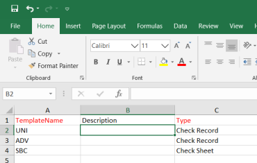


The details of the CR/CS templates in the worksheet will be displayed in the MC/SC – CR/CS Templates page.
7.5 Test Pack Contents
The Test Pack Contents page used to view a list of reports of the documents included in the Test Pack. To view the test pack content’s report,
- Click Test Pack Contents in the Test Pack menu.
The Test Pack Contents page opens.

Figure 7.5: Test Pack Contents page
-
In the Test Pack Name box, select a test pack from a drop-down list.
The Test Pack Contents page shows a list of reports in the selected test pack.
 Note: If you want to view any specific report, click the respective (Print icon) in the Print column.
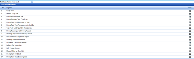

7.6 Joints Not in Any Test Pack Report
The Joints Not in Any Test Pack Report tab in the Test Pack menu shows a list of joints not added in any test pack report. To view of the details of joints,
- Click Joints Not in Any Test Pack Report in the Test Pack menu.
-
The Joints Not in Any Test Pack Report page opens with a list of joints, which are not added in any test pack report.
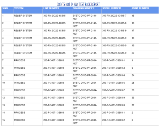
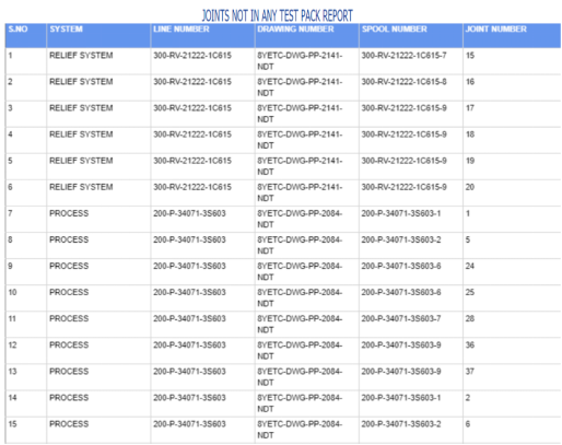
7.7 Overall Status
The Overall Status tab in the Test Pack menu helps you to view the overall status of NDT inspection, welding progress and piping. To view the overall status,
-
Click Overall Status in the Test Pack menu.
The page shows the overall status.


7.8 Acid Pickling Certificate
Pickling is a metal surface treatment used to remove impurities such as stains, inorganic contaminants, rust or scale from ferrous metals, copper, precious metals and aluminum alloys. A solution called pickle liquor, which usually contains acid, is used to remove the surface impurities.
The Acid Pickling Certificate tab in the Test Pack menu used to add the acid pickling certificate. To add the acid pickling certificate, do the following steps,
- Click Acid Pickling Certificate in the Test Pack menu.
The View Acid Pickling Certificate page opens.

Figure 7.8: View Acid Pickling Certificate page
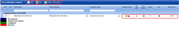
7.8.1 Add an Acid Pickling Certificate
If you want to add an acid pickling certificate, do the following steps,
- Click
 (ADD button) in the View Acid Pickling Certificate page.
The ACID PICKLING page opens.
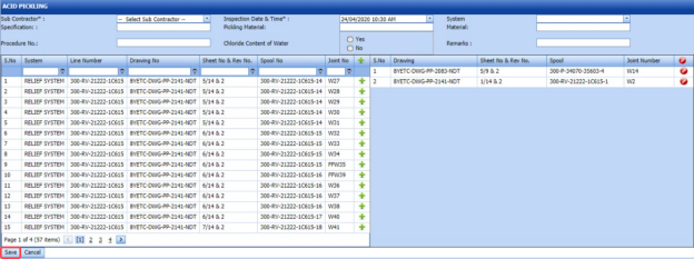
-
In the Sub Contractor box, select a sub-contractor from a drop-down list.
-
In the Inspection Date & Time box, select the inspection date and time.
-
In the Specification box, enter the specification.
-
In the Pickling Material box, enter the name of the pickling material.
-
In the System Material box, select the system material.
-
In the Procedure No box, enter the procedure number.
- If you use the chloride content of water for the acid pickling testing, select Yes in the Chloride Content of Water option otherwise select No.
-
In the Remarks box, enter your remarks if any.
Before saving the added acid pickling certificate, you must add joints for the acid pickling certificate.
 Note: You can add multiple joints for one acid pickling certificate.
The ACID PICKLING page shows a list of joints for the corresponding line and drawing numbers including the spool number. If you want to add joints for the acid pickling certificate, do the following steps,
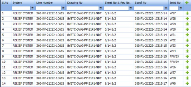
- Click
 (Add icon) of the respective joints you want to add.
The added joints will be moved and listed in the right side of the page.

-
Click Save.
The acid pickling certificate will be added and listed in the View Acid Pickling Certificate page.


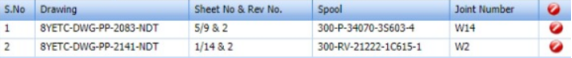
7.8.2 Edit an Acid Pickling Certificate
If you want to edit any existing acid pickling certificate added in the View Acid Picking Certificate page, do the following steps,
- Click
 (Edit icon) in the Edit column for the respective acid pickling certificate. See Fig 10.8.
The ACID PICKLING page opens with the details of the selected acid pickling certificate.
-
Click any box where you want to edit the details, and then edit the details in the respective box.
-
Click Save.

7.8.3 Approve an Acid Pickling Certificate
Once you have added the acid pickling certificate, the Request Status column in the View Acid Pickling Certificate page is appeared with (Approve and Reject icons).
- If you want to approve the acid pickling certificate, click
 (Approve icon) in the Request Status column. Otherwise click
  (Reject icon) to reject the certificate.


7.8.4 Add RFI Data for an Acid Pickling Certificate
If you want to add the details of RFI data for the added acid pickling certificate, do the following steps,
- Click
 (Edit icon) in the RFI Data column of the View Acid Pickling Certificate See Fig 7.8.
The RFI Inspection Request List window opens.
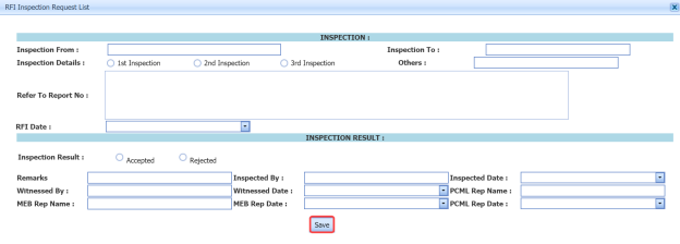
-
In the Inspection From box, enter the detail from where the inspection should start.
-
In the Inspection To box, enter the detail to where the inspection should end.
- In the Inspection Details option, select 1stInspection, 2nd Inspection or 3rd Inspection according to the inspection details.
-
In the Others box, enter any other inspection related details.
-
In the Refer to Report No box, enter the report number for reference.
-
In the RFI Date box, choose the RFI date.
- In the Inspection Result option, if the inspection result is accepted, select Accepted otherwise select Rejected.
- In the Remarks box, enter your remarks if any.
-
In the Inspected by box, enter the name of a person who has done inspection.
-
In the Inspected Date box, choose the date of inspection.
-
In the Witnessed By box, enter the name of the witnessed person.
-
In the Witnessed Date box, choose the date of witnessed.
-
In the PCML Rep Name box, enter the representative name of PCML.
-
In the PCML Rep Date box, choose the PCML rep date.
-
In the MEB Rep Name box, enter the representative name of MEB.
-
In the MEB Rep Date box, choose MEB rep date.
-
Click Save.


The RFI data for the acid pickling certificate is added successfully.
7.8.5 View an RFI Report for Acid Pickling Certificate
If you want to view an RFI report for the acid pickling certificate, click  (print icon) provided in the RFI Report column of the View Acid Pickling Certificate page. See Fig 7.8.
7.8.6 View an Acid Pickling Report
If you want to view the acid pickling report, click  (print icon) provided in the Print column of the View Acid Pickling Certificate page. See Fig 7.8.
7.8.7 Add Result for Acid Pickling Test
After completing the acid pickling test for the added request, you can add the result details. To add results, do the following steps,
- Click
 (Edit icon) in the RFI Data column of the View Acid Pickling Certificate page.
The Result window opens a list of systems added for the particular request.

-
In the Result column, select the result of each system from the given result options in the drop-down list.
-
In the Remarks column, enter your remarks if any.
-
Click Save.

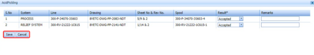
7.8.8 Attach a File into an Acid Pickling Certificate
If you want to attach a file with any acid pickling certificate listed in the View Acid Pickling Certificate page, you can attach the file by using  (Attach icon) in the Attachment column. To know how to attach, follow the procedures given in the topic “Attach a file into P&ID”.
7.8.9 Export Acid Pickling Certificate List
You can export a list of acid pickling certificates added in the View Acid Pickling Certificate page in both the pdf and excel formats by using  (PDF button) and
  (Excel button). To know how to export, see the topic, “Export P&ID list”.
7.8.10 Filter an Acid Pickling Certificate
If you want to filter any specific acid pickling certificate in the View Acid Pickling Certificate page, you can use  (FILTER button) located on the View Acid Pickling Certificate page. To know how to filter, see the topic, “Filter P&ID”.
7.9 Valve Leak Test Record
All valves are inspected and tested by the inspectors to ensure that they conform to the required valve leakage standards. Valve leakage is tested using either a hydrostatic test that is the test medium is a liquid, such as water or kerosene, or a pneumatic test that is the test medium is a gas, such as air or nitrogen.
The Valve Leak Test Record tab in the Test Pack menu used to add the valve leak test report. To add the valve leak test report, do the following steps,
- Click Valve Leak Test Record in the Test Pack menu.
The Valve Leak Test page opens.

Figure 7.9: Valve Leak Test page
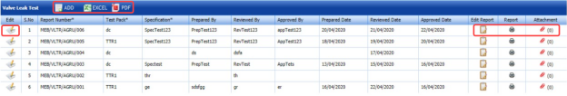
7.9.1 Add a Valve Leak Test Report
If you want to add a valve leak test report, do the following steps,
- Click
 (ADD button) in the Valve Leak Test page.
A new window opens to add the details of the valve leak test report.

 Note: The fields notified with a symbol (*) are mandatory. You must enter the relevant details in that fields before saving.
 Tip: A report number for a new valve leak test report will be updated automatically in the Report Number box. If you want change the report number, you can change.
 -
In the Test Pack box, select a test pack from a drop-down list.
-
In the Specification box, enter the specification.
- In the Prepared By box, enter the name a person who has prepared the valve leak test report.
- In the Prepared Date box, enter the prepared date of the valve leak test report.
- In the Reviewed By box, enter the name a person who has reviewed the valve leak test report.
- In the Reviewed Date box, enter the reviewed date of the valve leak test report.
-
In the Approved By box, enter the name a person who has approved the valve leak test report.
- In the Approved Date box, enter the approved date of the valve leak test report.
-
Click Save.


The valve leak test report will be added and listed in the Valve Leak Test page.
7.9.2 Edit a Valve Leak Test Report
If you want to edit any existing valve leak test report added in the Valve Leak Test page, do the following steps,
- Click
 (Edit icon) in the Edit column for the respective valve leak test report. See Fig 7.9.
The Valve Leak Test page opens with the details of the selected valve leak test report.
- Click any box where you want to edit the details, and then edit the details in the respective box.
-
Click Save.

7.9.3 Add Result for Valve Leak Test
After completing the valve leak test, you can add the test result details. To add results, do the following steps,
- Click
 (Edit icon) in the Edit Report column of the Valve Leak Test page.
The Result window opens.

-
Click (Add button).

-
In the Valve Type box, enter the type of the valve.
-
In the Location box, enter the location of the valve.
-
In the Size box, enter the size of the valve.
-
In the Rating box, enter the rating of the valve.
-
In the Tag Number box, enter the tag number of the valve.
-
In the Serial No box, enter the serial number of the valve.
-
In the Body Test (Hydro) box, enter the detail of hydrostatic valve body test.
-
In the Seat Test (Hydro) box, enter the detail of the hydrostatic valve seat test.
-
In the Body Test (Pneumatic) box, enter the detail of pneumatic valve body test.
-
In the Seat Test (Pneumatic) box, enter the detail of the pneumatic valve seat test.
-
In the Results box, select the results whether Accepted or Rejected.
-
In the Remarks box, enter your remarks if any.
-
Click Save.

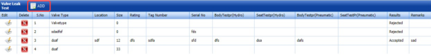
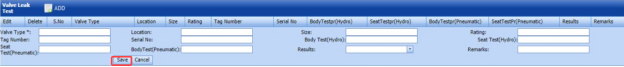
7.9.4 View a Valve Leak Test Report
If you want to view the valve leak test report, click  (print icon) provided in the Report column of the Valve Leak Test page. See Fig 7.9.
7.9.5 Attach a File into a Valve Leak Test Report
If you want to attach a file with any valve leak test report listed in the Valve Leak Test page, you can attach the file by using  (Attach icon) in the Attachment column. To know how to attach, follow the procedures given in the topic “Attach a file into P&ID”.
7.9.6 Export Valve Leak Test Report List
You can export a list of valve leak test reports added in the Valve Leak Test page in both the pdf and excel formats by using  (PDF button) and
  (Excel button). To know how to export, see the topic, “Export P&ID list”.
7.10 ITR Register (Generic)
The ITR Register (Generic) tab in the Test Pack menu used to add the ITR register.
-
Click ITR Register (Generic) in the Test Pack menu.
The ITR Register (Generic) page opens.

Figure 10.10: ITR Register (Generic) page
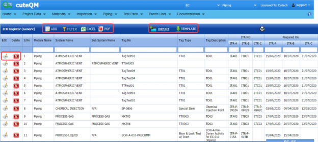
7.10.1 Add an ITR Register
If you want to add an ITR Register,
- Click (Add button) in the ITR Register (Generic) page.
The ITR Register (Generic) page opens a new window to add the details of the ITR register.

-
In the System box, enter the system name.
-
In the Sub System box, enter the subsystem name.
-
In the Tag No box, enter the tag number.
-
In the Tag Type box, enter the tag type.
-
In the Tag Description box, enter the tag description.
The page shows three options such as ITR-A Check Sheet (Construction), ITR-B Check Sheet (Pre-Commissioning), ITR-C Check Sheet (Commissioning).
You must add the following details for each option individually.
-
In the ITR No box, enter the ITR number for each option.
-
In the Prepared by MEB box, select the prepared date of ITR register for each option.
-
In the Submitted to Client box, select the submitted date of ITR register for each option.
-
In the Accepted to Client box, select the accepted date of ITR register for each option.
-
Click Save.
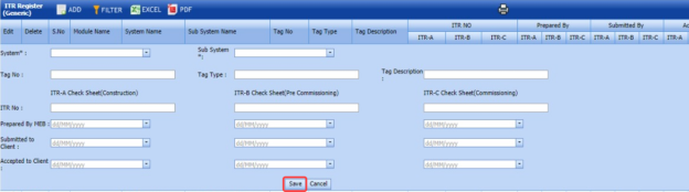
The ITR register will be saved and listed in the ITR Register (Generic) page.
7.10.2 Edit an ITR Register
If you want to edit any existing ITR register in the ITR Register (Generic) page, do the following steps,
- Click
 (Edit icon) in the Edit column for the respective ITR register. See Fig 7.10.
The ITR Register (Generic) page shows the details of the added ITR register.
-
Click any box where you want to edit the details, and then edit the details in the respective box.
-
Click Save.

7.10.3 Delete an ITR Register
If you want to delete any ITR register in the ITR Register (Generic) page, you can use  (Delete icon) provided in the ITR Register (Generic) page. To know how to delete, see the topic, “Delete P&ID”.
7.10.4 View an ITR Register Report
If you want to view the ITR register report, click  (print icon) provided in the upper side of the ITR Register (Generic) page. See Fig 7.10.
7.10.5 Filter an ITR Register
If you want to filter any ITR register in the ITR Register (Generic) page, you can use  (FILTER button) located on the ITR Register (Generic) page. To know how to filter, see the topic, “Filter P&ID”.
7.10.6 Export an ITR Register
You can export the ITR Register in the ITR Register (Generic) page in both the pdf and excel formats by using  (PDF button) and
  (Excel button). To know how to export, see the topic, “Export P&ID list”.
7.10.7 Import Multiple ITR Register
If you want to import multiple ITR register together, do the following,
- Click
 (TEMPLATE button). See Fig 7.10.
An excel worksheet will be downloaded with a predefined template to enter the details of ITR register.

- Enter the required ITR register details in the respective columns of the excel worksheet.
-
Once you have added the ITR register details in the excel worksheet, save the excel worksheet on your computer.
-
Click
 (IMPORT button). See Fig 7.10.
A new window opens for importing the excel worksheet saved on your computer.

-
Click
 (Browse button) to select the excel worksheet to be uploaded.
 -
Select the excel worksheet you want to upload from your computer.
-
Click
 (Upload button) to export the ITR register details that are included in the excel worksheet.


The details of the ITR register in the worksheet will be displayed in the ITR Register (Generic) page.
7.10 ITR Register Summary
The ITR Register Summary tab in the Test Pack menu helps you to view the ITR register summary report. To view the report,
- Click ITR Register Summary in the Test Pack menu.
The ITR Register (Generic) Summary Report page opens.
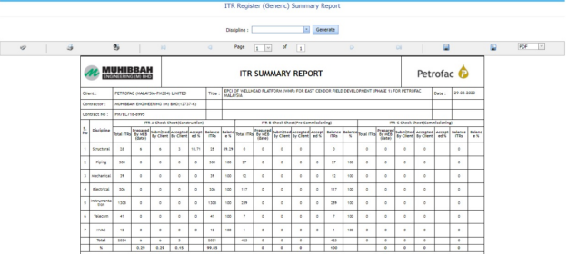
Figure 10.11: ITR Register (Generic) Summary Report page

7.11.1 Print an ITR Register Summary Report
If you want to print an ITR register summary report, use  and
and  (print icons) provided in the ITR Register (Generic) Summary Report page.
- If you want to print the current page of the ITR register summary report, click
 (print icon including the page number).
 -
If you want to print all the pages of the ITR register summary report, click
 (print icon).


7.11.2 View an ITR Register Summary Report
You can view the ITR register summary report in various formats by using the option  provided in the upper right corner of the ITR Register (Generic) Summary Report page.
7.12 Management of Change
Management of change (MOC) is a systematic approach to organizational changes with the aim of ensuring the continued safety of the workforce throughout the process. These systematic processes ensure that the change is dealt with in a proactive fashion.
The Management of Change tab in the Test Pack menu used to add the details of the management of change.
- Click Management of Change in the Test Pack menu.
The Management of Change page opens.
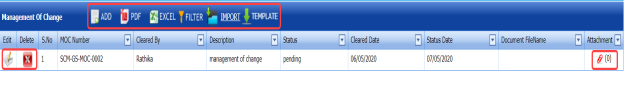
Figure 7.12: Management of Change page

7.12.1 Add the Details of Management of Change
If you want to add the details of the management of change, do the following steps,
- Click
 (Add button) in the Management of Change page.
The page shows a new window to add the details of the management of change.
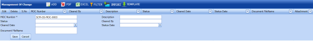
-
In the MOC Number box, enter the management of change number.
-
In the Description box, enter the description for the management of change.
-
In the Status box, enter the status of the management of change.
-
In the Cleared by box, enter the name of a person who has cleared the management of change.
-
In the Cleared Date box, select the cleared date of the management of change.
-
In the Status Date box, select the status date of the management of change.
-
In the Document File Name box, enter the document file name.
-
Click Save.
The management of change is added and listed in the Management of Change page.


7.12.2 Edit a Management of Change
If you want to edit any existing management of change in the Management of Change page, do the following steps,
- Click
 (Edit icon) in the Edit column for the respective management of change. See Fig 7.12.
The page opens with the details of the selected management of change.
-
Click any box where you want to edit the details, and then edit the details in the respective box.
-
Click Save.

7.12.3 Attach a File into a Management of Change
If you want to attach a file with any existing management of change listed in the Management of Change page, you can attach the file by using  (Attach icon) in the Attachment column. To know how to attach, follow the procedures given in the topic “Attach a file into P&ID”.
7.12.4 Export Management of Change List
You can export a list of management of change added in the Management of Change page in both the pdf and excel formats by using  (PDF button) and
  (Excel button). To know how to export, see the topic, “Export P&ID list”.
7.12.5 Filter a Management of Change
If you want to filter any specific management of change in the Management of Change page, you can use  (FILTER button) located on the Management of Change page. To know how to filter, see the topic, “Filter P&ID”.
7.12.6 Import Multiple Management of Change
If you want to import multiple management of change together, do the following,
-
Click
 (TEMPLATE button). See Fig 7.12.
An excel worksheet will be downloaded with a predefined template to enter the details of management of change.
-
Enter the required management of change details in the respective columns of the excel worksheet.
-
Once you have added the management of change details in the excel worksheet, save the excel worksheet on your computer.
-
Click
 (IMPORT button). See Fig 7.12.
A new window opens for importing the excel worksheet saved on your computer.

- Click
 (Browse button) to select the excel worksheet to be uploaded.
 -
Select the excel worksheet you want to upload from your computer.
- Click
 (Upload button) to export the management of change that are included in the excel worksheet.


The details of the management of change in the worksheet will be displayed in the Management of Change page.
7.13 Technical Queries
Technical queries are used by companies and their contractors to ask each other questions or to gather more information.
The Technical Queries tab in the Test Pack menu used to add the details of the technical query.
- Click Technical Queries in the Test Pack menu.
The Technical Queries page opens.

Figure 7.13: Technical Queries page

7.13.1 Add the Details of Technical Query
If you want to add the details of the technical query, do the following steps,
-
Click
 (Add button) in the Technical Queries page.
The page shows a new window to add the details of the technical query.
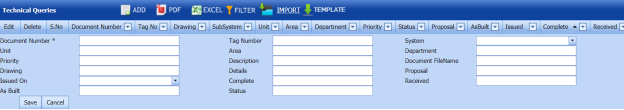
-
In the Document Number box, enter the document number.
-
In the Tag Number box, enter the tag number.
-
In the System box, select a system.
-
In the Unit box, enter the name of a unit.
-
In the Area box, enter the name of an area.
-
In the Department box, enter the department name.
-
In the Priority box, enter the priority detail.
-
In the Description box, enter the description of the technical query.
-
In the Document File Name box, enter the document file name.
-
In the Drawing box, enter the drawing number.
-
In the Issued on box, enter the issued date of technical query.
-
In the Status box, enter the status of the technical query.
-
Click Save.
The technical query is added and listed in the Technical Queries page.


7.13.2 Edit a Technical Query
If you want to edit any existing technical query in the Technical Queries page, do the following steps,
- Click
 (Edit icon) in the Edit column for the respective technical query. See Fig 7.13.
The page opens with the details of the selected technical query.
- Click any box where you want to edit the details, and then edit the details in the respective box.
-
Click Save.

7.13.3 Attach a File into a Technical Query
If you want to attach a file with any existing technical query listed in the Technical Queries page, you can attach the file by using  (Attach icon) in the Attachment column. To know how to attach, follow the procedures given in the topic “Attach a file into P&ID”.
7.13.4 Export Technical Queries List
You can export a list of technical queries added in the Technical Queries page in both the pdf and excel formats by using  (PDF button) and
  (Excel button). To know how to export, see the topic, “Export P&ID list”.
7.13.5 Filter a Technical Query
If you want to filter any specific technical query in the Technical Queries page, you can use  (FILTER button) located on the Technical Queries page. To know how to filter, see the topic, “Filter P&ID”.
7.13.6 Import Multiple Technical Queries
If you want to import multiple technical queries together, do the following,
- Click
 (TEMPLATE button). See Fig 7.13.
An excel worksheet will be downloaded with a predefined template to enter the details of technical query.
- Enter the required technical query details in the respective columns of the excel worksheet.
- Once you have added the technical query details in the excel worksheet, save the excel worksheet on your computer.
- Click
 (IMPORT button). See Fig 7.13.
A new window opens for importing the excel worksheet saved on your computer.

- Click
 (Browse button) to select the excel worksheet to be uploaded.
 -
Select the excel worksheet you want to upload from your computer.
-
Click
 (Upload button) to export the technical query that are included in the excel worksheet.


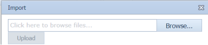


The details of the technical query in the worksheet will be displayed in the Technical Queries page.
7.14 Site Instructions
A site instruction is a formal instruction sent from the head contractor that contains directives for contractors working on a piping project.
The Site Instructions tab in the Test Pack menu used to add the details of the site instruction.
- Click Site Instructions in the Test Pack menu.
The Site Instructions page opens.
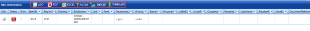

7.14.1 Add the Details of Site Instructions
If you want to add the details of the site instruction, do the following steps,
- Click
 (Add button) in the Site Instructions page.
The page shows a new window to add the details of the site instruction.
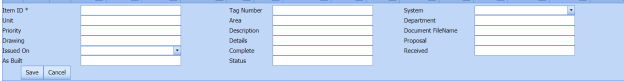
-
In the Item ID box, enter the item id number.
-
In the Tag Number box, enter the tag number.
-
In the System box, select a system.
-
In the Unit box, enter the name of a unit.
-
In the Area box, enter the name of an area.
-
In the Department box, enter the department name.
-
In the Priority box, enter the priority detail.
-
In the Description box, enter the description of the technical query.
-
In the Document File Name box, enter the document file name.
-
In the Drawing box, enter the drawing number.
-
In the Issued on box, enter the issued date of technical query.
-
In the Status box, enter the status of the technical query.
-
Click Save.
The site instruction is added and listed in the Site Instructions page.


7.14.2 Edit a Site Instruction
If you want to edit any existing site instruction in the Site Instructions page, do the following steps,
- Click
 (Edit icon) in the Edit column for the respective site instruction. See Fig 7.14.
The page opens with the details of the selected site instruction.
- Click any box where you want to edit the details, and then edit the details in the respective box.
-
Click Save.

7.14.3 Attach a File into a Site Instruction
If you want to attach a file with any existing site instruction listed in the Site Instructions page, you can attach the file by using  (Attach icon) in the Attachment column. To know how to attach, follow the procedures given in the topic “Attach a file into P&ID”.
7.14.4 Export Site Instructions List
You can export a list of site instructions added in the Site Instructions page in both the pdf and excel formats by using  (PDF button) and
  (Excel button). To know how to export, see the topic, “Export P&ID list”.
7.14.5 Filter a Site Instruction
If you want to filter any specific site instruction in the Site Instructions page, you can use  (FILTER button) located on the Site Instructions page. To know how to filter, see the topic, “Filter P&ID”.
7.14.6 Import Multiple Site Instructions
If you want to import multiple site instructions together, do the following,
- Click
 (TEMPLATE button). See Fig 7.14.
An excel worksheet will be downloaded with a predefined template to enter the details of site instruction.
- Enter the required site instruction details in the respective columns of the excel worksheet.
- Once you have added the site instruction details in the excel worksheet, save the excel worksheet on your computer.
- Click
 (IMPORT button). See Fig 7.14.
A new window opens for importing the excel worksheet saved on your computer.

- Click
 (Browse button) to select the excel worksheet to be uploaded.
 -
Select the excel worksheet you want to upload from your computer.
-
Click
 (Upload button) to export the site instruction that are included in the excel worksheet.


The details of the site instruction in the worksheet will be displayed in the Site Instructions page.
7.15 Test Pack Status Report
Test Pack Status Report shows the status of test pack.
If you want to view a test pack status report, do the following steps,
- Click Test Pack Status Report in the Piping menu.
The Test Pack Status Report page opens.

Figure 7.15: Test Pack Status Report page
- In the ISO/Drawing Number box, select the ISO/drawing from a drop-down list.
- In the Spool Number box, select the spool number from a drop-down list.
-
Click Go.
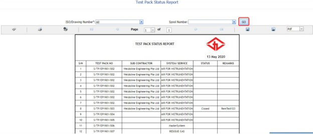
The Test Pack Status Report page shows the test pack number, subcontractor name, system/service information, and test pack status.
7.15.1 Print a Test Pack Status Report
If you want to print the test pack status report, use  and
and  (print icons) provided in the Test Pack Status Report page. See Fig 7.15.
- If you want to print the current page of the test pack status report, click
 (print icon including the page number).
 -
If you want to print all the pages of the test pack status report, click
 (print icon).


7.15.2 Export a Test Pack Status Report
You can export the test pack status report in various formats by using the option provided in the upper right corner of the Test Pack Status Report page.
Punch Lists
8.0 Punch List
A punch list is a list of items or tasks that need to be done before a piping project is completed. The Punch Lists menu in the home page of the cuteQM app helps to create and view the punch lists in Piping project.
8.1 Create a New Punch List
If you want to create a punch list, do the following steps,
- Click Create New Punch List in the Punch lists menu.
The Create Punch page opens.

Figure 8.1: Create Punch page
-
In the Modules box, select a module from the given modules.
-
In the Systems box, select a system from a drop-down list.
-
In the Sub-Systems box, select a sub-system from a drop-down list.
-
In the ITR No box, enter the ITR number.
-
In the Drawing No box, enter the drawing number.
-
In the Test Pack box, select a test pack from a drop-down list.
-
In the Tag No box, enter the tag number.
-
In the Reference Types box, select the reference type from the given options.
-
In the Select Project box, select a project from a drop-down list.
-
In the Category box, select any category from the given categories such as A, B, and C.
A - Item to be cleared before hydrostatic test.
B - Item to be cleared after hydrostatic test.
C - Item which can be cleared after hydrostatic test but before final acceptance of the whole plant.
-
In the Type box, select the type of punch such as whether internal or external.
- In the Item box, enter the item details.
-
In the Location box, select a location from a drop-down list.
-
In the Description/ Punch box, enter the description for the punch list.
- In the Punch Raised From box, select the detail such as from where the punch has been raised.
-
In the Date Raised box, select the date when the punch has been raised.
-
In the Punch Raised By box, enter the name of a person who has raised the punch.
-
In the Responsible Dept box, enter the department name, which is responsible for the punch.
-
In the Responsible Person box, enter the name of a person who is responsible for the punch.
-
In the Expected Clearance box, select the expected date of clearing the punch list.
-
Click Save.
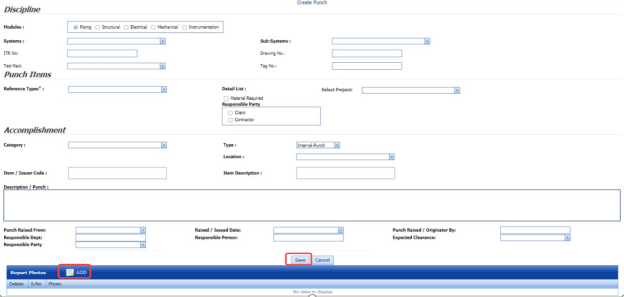
The punch list is successfully added.
8.1.1 Add Report Photos
If you want to add any report photos for the punch list,
- Click
 (ADD button) in the Report Photos box.

-
Click
 (Browse button) to browse a photo stored in your computer.
 -
Click Upload.


The selected photo will be updated.
8.2 View Punch Lists
The View Punch Lists tab helps you to view and edit the punch list, which is added by using the Create New Punch List tab.
- Click View Punch Lists in the Punch Lists menu.
The Punch List page opens with added punch lists.

Figure 8.2: Punch List page
 Note: If you want to verify the added punch list item, click the checkbox provided in the Verify column.
 If you want to clear the added punch list item, click the checkbox provided in the Clear column.
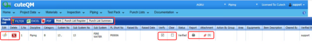

8.2.1 View a Punch List Report
If you want to view a punch list report, click  (Print button) provided in the upper side of the Punch List page. See Fig 11.2.
8.2.2 View a Punch List Register
If you want to view a punch list register, click  (Punch List Register button) provided in the upper side of the Punch List page. See Fig 8.2.
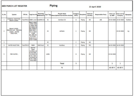
8.2.3 View a Punch List Summary
If you want to view a punch list summary, click  (Punch List Summary button) provided in the upper side of the Punch List page. See Fig 8.2.
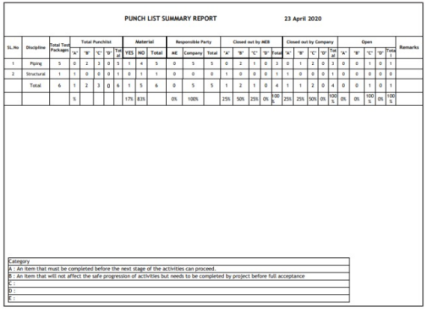
8.2.4 Attach a File into a Punch List
If you want to attach any file with any punch list listed in the Punch List page, you can attach the file by using  (Attach icon) in the Attachment column. To know how to attach, follow the procedures given in the topic “Attach a file into P&ID”.
8.2.5 Edit a Punch List
If you want to edit any existing punch list in the Punch List page, click  (Edit icon) in the Edit column for the respective punch list. See Fig 8.2. Edit the details in the respective box you want.
8.2.6 Export Punch Lists
You can export a list of punch lists added in the Punch List page in both the pdf and excel formats by using  (PDF button) and
  (Excel button). To know how to export, see the topic, “Export P&ID list”.
8.2.7 Filter a Punch List
If you want to filter any punch list in the Punch List page, you can use  (FILTER button) located on the Punch List page. To know how to filter, see the topic, “Filter P&ID”.
8.3 Punch List Detail Report
The Punch List Detail Report tab in the Punch Lists menu helps you to view a detailed report of the punch lists. To view the punch list detail report,
- Click Punch List Detail Report in the Punch Lists menu.
The Punch List Detail Report page opens.

Figure 11.3: Punch List Detail Report page
- In the Modules field, select Piping from the given modules.
-
In the Systems box, select a system from a drop-down list.
-
In the Sub Systems box, select a sub-system from a drop-down list.
-
In the ITR No box, enter the ITR number.
-
In the Drawing box, enter the drawing number.
-
In the Category box, select a category from a list.
-
In the Status box, select a status from a drop-down list.
-
In the Punch Raised From box, select a person who has raised the punch list.
-
In the Responsible Party box, select a responsible party from a drop-down list.
-
In the Test Pack box, select a test pack from a drop-down list.
-
In the Tag No box, enter the tag number.
-
In the Raised Date box, select a raised date of the punch list.
The punch list report opens based on the selected data.
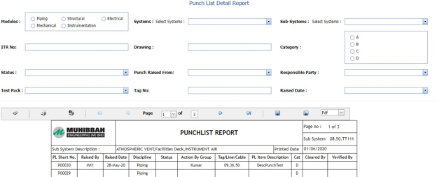
8.3.1 Print a Punch List Detail Report
If you want to print the punch list detail report, use  and
and  (print icons) provided in the Punch List Detail Report page.
- If you want to print the current page of the punch list detail report, click
 (print icon including the page number).
 - If you want to print all the pages of the punch list detail report, click
 (print icon).


8.3.2 View a Punch List Detail Report
You can view the punch list detail report in various formats by using the option  provided in the upper right corner of the punch list detail report page.
8.4 Punch List System Report
The Punch List System Report tab in the Punch Lists menu helps you to view a punch list system report. To view the punch list system report,
- Click Punch List System Report in the Punch Lists menu.
The Punch List System Report page opens.
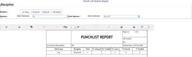
Figure 8.4: Punch List System Report page
-
In the Modules field, select Piping from the given modules.
-
In the Systems box, select a system from a drop-down list.
-
In the Sub Systems box, select a sub-system from a drop-down list.
The punch list system report opens based on the selected data.

8.4.1 Print a Punch List System Report
If you want to print the punch list system report, use  and
and  (print icons) provided in the Punch List system Report page.
- If you want to print the current page of the punch list system report, click
 (print icon including the page number).
 - If you want to print all the pages of the punch list system report, click
 (print icon).


8.4.2 View a Punch List System Report
You can view the punch list system report in various formats by using the option  provided in the upper right corner of the punch list system report page.
8.5 Punch List Sub System Report
The Punch List Sub System Report tab in the Punch Lists menu helps you to view a punch list sub system report. To view the punch list sub system report,
- Click Punch List Sub System Report in the Punch Lists menu.
The Punch List Sub System Report page opens.

Figure 8.5: Punch List Sub System Report page
-
In the Modules field, select Piping from the given modules.
-
In the Systems box, select a system from a drop-down list.
-
In the Sub Systems box, select a sub-system from a drop-down list.
The punch list sub system report opens based on the selected data.
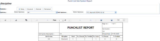
8.5.1 Print a Punch List Sub System Report
If you want to print the punch list sub system report, use  and
and  (print icons) provided in the Punch List Sub System Report page.
- If you want to print the current page of the punch list sub system report, click
 (print icon including the page number).
 - If you want to print all the pages of the punch list sub system report, click
 (print icon).


8.5.2 View a Punch List Sub System Report
You can view the punch list sub system report in various formats by using the option  provided in the upper right corner of the punch list sub system report page.
8.6 Punch List Category Report
The Punch List Category Report tab in the Punch Lists menu helps you to view a punch list category report. To view the punch list category report,
- Click Punch List Category Report in the Punch Lists menu.
The Punch List Category Report page opens.

Figure 8.6: Punch List Category Report page
-
In the Modules field, select Piping from the given modules.
-
In the Systems box, select a system from a drop-down list.
-
In the Sub Systems box, select a sub-system from a drop-down list.
The punch list category report opens based on the selected data.
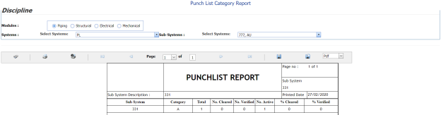
8.6.1 Print a Punch List Category Report
If you want to print the punch list category report, use  and
and  (print icons) provided in the Punch List Category Report page.
- If you want to print the current page of the punch list category report, click
 (print icon including the page number).
 -
If you want to print all the pages of the punch list category report, click
 (print icon).


8.6.2 View a Punch List Category Report
You can view the punch list category report in various formats by using the option  provided in the upper right corner of the punch list category report page.
Documentation
9.0 Documentation
The Documentation menu used to combine the number of files, which are attached to every menu of this cuteQM app. The combined files will be shown as a pdf file. This menu also used to attach a new file to a module that is not provided with an attachment option to attach any file.
9.1 Document Category
The Document Category tab in the Documentation menu used to attach a file to any module which has no attachment option to attach the file. Before attaching a file for any module, you must add the relevant category name of the module.
9.1.1 Add a Document Category
- Click Document Category in the Documentation menu.
The Document Category page opens.

Figure 9.1: Document Category page
- Click
 (ADD button) in the Document Category page.
A new window opens to add a document category.
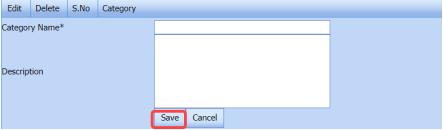
-
In the Category Name box, enter the relevant category name for the module for which you want to attach a file.
-
In the Description box, enter the description for the added category.
-
Click Save.
(OR)
- If you want to import any document category from another vessel, Click Import from Another Vessel.
The Import from Another Vessel window opens.
-
-
In the Equipment box, select an equipment from a drop-down list.
-
Click Save.
-
-
-
The added category name will be listed in the Document Category page. Once you have added the document category, you can attach any file to the added category.
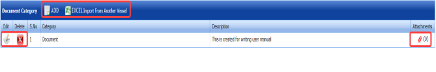


9.1.2 Attach a File into an Added Category
If you want to attach any file with the added category listed in the Document Category page, you can attach the file by using  (Attach icon) in the Attachment column. To know how to attach, follow the procedures given in the topic “Attach a file into P&ID”.
9.1.3 Edit a Category
If you want to edit any existing category in the Document Category page, click  (Edit icon) for the respective category, and then edit the details in the respective box.
9.1.4 Delete a category
If you want to delete any specific added category from the list, you can use  (Delete icon) provided in the Delete column of the Document Category page, See Fig 9.1.
9.2 Hierarchical Report
The Hierarchical Report tab in the Documentation menu helps you to view a hierarchical report of a project. If you want to view the hierarchical report,
-
Click Hierarchical Report in the Documentation menu.
The hierarchical report page opens.
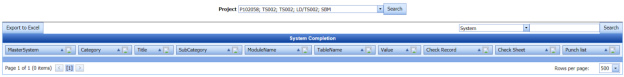
-
In the Project box, select a project for which you want to view he hierarchical report.
-
Select a category that is whether System, Sub-System, or Tag No.
-
Click Search.
The page shows the hierarchical report for the selected project and category.

 Note: If you want to export the hierarchical report as excel file, click Export to Excel.

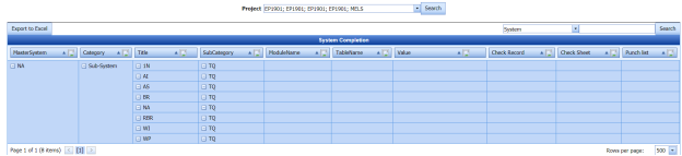

9.3 Manufacture Data Report (MDR) Settings
The MDR Settings tab in the Documentation menu helps you to do page setup for the pdf file which will be shown after combining the attached files.
- Click the MDR Settings tab.
The MDR Settings page opens.

Figure 9.3: MDR Settings page
-
In the Page Numbering box, select the page numbering option that is whether Section wise or Continuous.
- In the Page Number (Digits) box, select the page number displaying format from a drop-down list.
-
If you want to append the section number with the page number, click Yes, otherwise click No in the Append Section number with Page number box.
- In the Page Number Template box, select the page number template from a drop-down list.
- If you want to add the starting page numbers from TOC, click Yes, otherwise click No in the Page Number Starting From TOC? box.
-
If you want to add alphabet page numbers, click Yes, otherwise click No in the Alphabet Page number? box.
-
In the Logo box, attach your logo by using (Browse button).
-
Click Save.
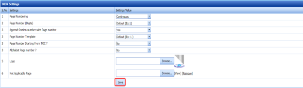
9.4 One Click Documentation
The One Click Documentation tab used to combine the attached file of the various module.
- Click One Click Documentation in the Documentation menu.
The One Click Documentation page opens.
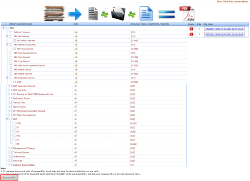
Figure 9.4: One Click Documentation page
The One Click Documentation page shows a list of reports name of each module including the attachment file counts. This page also shows the list of document categories including their attachments, which are added using the Document Category tab.
 Note: If you want to edit any existing category in the Document Category page, click (Edit icon) for the respective category, and then edit the details in the respective box.
 -
Click the check box of the respective reports which you want to combine.
-
Click Generate MDR.
The system combines the selected files and shows as the pdf file in the left side of the One Click Documentation page, See Fig 9.4.
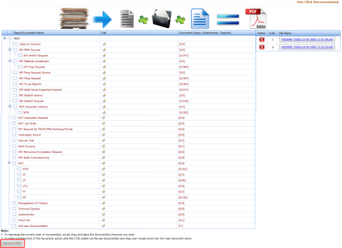

 Tip: You can view the pdf file by clicking the respective pdf file. The file will be opened including the data in the combined files.
9.5 Document Upload
The Document Upload tab in the Documentation menu used to upload documents for various process.
- Click Document Upload in the Documentation menu.
The Upload Documents page opens.

Figure 9.5: Upload Documents page
- Select a file which you want to upload by click Select a file for upload.
The selected file will be added in the File Upload window.